tire pressure DODGE DART 2015 PF / 1.G User Guide
[x] Cancel search | Manufacturer: DODGE, Model Year: 2015, Model line: DART, Model: DODGE DART 2015 PF / 1.GPages: 164, PDF Size: 25.19 MB
Page 3 of 164
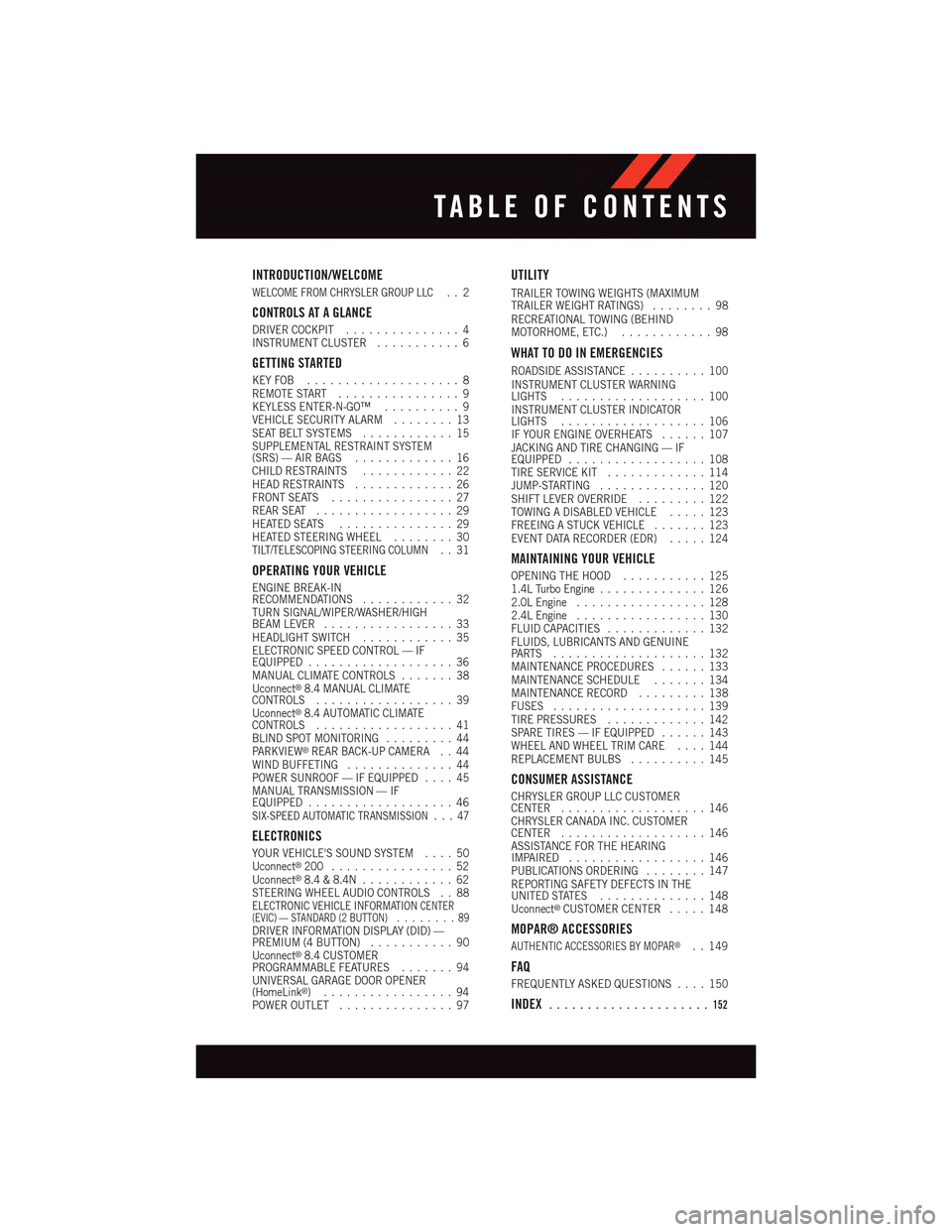
INTRODUCTION/WELCOME
WELCOME FROM CHRYSLER GROUP LLC..2
CONTROLS AT A GLANCE
DRIVER COCKPIT...............4INSTRUMENT CLUSTER...........6
GETTING STARTED
KEY FOB . . . . . . . . . . . . . . . . . . . . 8REMOTE START . . . . . . . . . . . . . . . . 9KEYLESS ENTER-N-GO™..........9VEHICLE SECURITY ALARM........13SEAT BELT SYSTEMS............15SUPPLEMENTAL RESTRAINT SYSTEM(SRS) — AIR BAGS.............16CHILD RESTRAINTS............22HEAD RESTRAINTS.............26FRONT SEATS................27REAR SEAT..................29HEATED SEATS . . . . . . . . . . . . . . . 29HEATED STEERING WHEEL........30TILT/TELESCOPING STEERING COLUMN..31
OPERATING YOUR VEHICLE
ENGINE BREAK-INRECOMMENDATIONS............32TURN SIGNAL/WIPER/WASHER/HIGHBEAM LEVER.................33HEADLIGHT SWITCH............35ELECTRONIC SPEED CONTROL — IFEQUIPPED...................36MANUAL CLIMATE CONTROLS.......38Uconnect®8.4 MANUAL CLIMATECONTROLS..................39Uconnect®8.4 AUTOMATIC CLIMATECONTROLS..................41BLIND SPOT MONITORING.........44PA R K V I E W®REAR BACK-UP CAMERA . . 44WIND BUFFETING..............44POWER SUNROOF — IF EQUIPPED....45MANUAL TRANSMISSION — IFEQUIPPED...................46SIX-SPEED AUTOMATIC TRANSMISSION . . . 47
ELECTRONICS
YOUR VEHICLE'S SOUND SYSTEM....50Uconnect®200 . . . . . . . . . . . . . . . . 52Uconnect®8.4 & 8.4N............62STEERING WHEEL AUDIO CONTROLS . . 88ELECTRONIC VEHICLE INFORMATIONCENTER(EVIC) — STANDARD (2 BUTTON) . . . . . . . . 89DRIVER INFORMATION DISPLAY (DID) —PREMIUM (4 BUTTON)...........90Uconnect®8.4 CUSTOMERPROGRAMMABLE FEATURES.......94UNIVERSAL GARAGE DOOR OPENER(HomeLink®).................94POWER OUTLET...............97
UTILITY
TRAILER TOWING WEIGHTS (MAXIMUMTRAILER WEIGHT RATINGS)........98RECREATIONAL TOWING (BEHINDMOTORHOME, ETC.)............98
WHAT TO DO IN EMERGENCIES
ROADSIDE ASSISTANCE..........100INSTRUMENT CLUSTER WARNINGLIGHTS...................100INSTRUMENT CLUSTER INDICATORLIGHTS...................106IF YOUR ENGINE OVERHEATS......107JACKING AND TIRE CHANGING — IFEQUIPPED..................108TIRE SERVICE KIT.............114JUMP-STARTING..............120SHIFT LEVER OVERRIDE.........122TOWING A DISABLED VEHICLE.....123FREEING A STUCK VEHICLE.......123EVENT DATA RECORDER (EDR).....124
MAINTAINING YOUR VEHICLE
OPENING THE HOOD...........1251.4L Turbo Engine..............1262.0L Engine.................1282.4L Engine.................130FLUID CAPACITIES.............132FLUIDS, LUBRICANTS AND GENUINEPA RT S . . . . . . . . . . . . . . . . . . . . 1 3 2MAINTENANCE PROCEDURES......133MAINTENANCE SCHEDULE.......134MAINTENANCE RECORD.........138FUSES....................139TIRE PRESSURES.............142SPARE TIRES — IF EQUIPPED......143WHEEL AND WHEEL TRIM CARE....144REPLACEMENT BULBS..........145
CONSUMER ASSISTANCE
CHRYSLER GROUP LLC CUSTOMERCENTER...................146CHRYSLER CANADA INC. CUSTOMERCENTER...................146ASSISTANCE FOR THE HEARINGIMPAIRED..................146PUBLICATIONS ORDERING........147REPORTING SAFETY DEFECTS IN THEUNITED STATES..............148Uconnect®CUSTOMER CENTER.....148
MOPAR® ACCESSORIES
AUTHENTIC ACCESSORIES BY MOPAR®..149
FAQ
FREQUENTLY ASKED QUESTIONS....150
INDEX.....................152
TABLE OF CONTENTS
Page 91 of 164
•Pushthebuttoninthecentertoselectthenextpresetstation(radio)ortochangeCDs
if equipped with a CD Changer.
ELECTRONIC VEHICLE INFORMATION CENTER (EVIC) —
STANDARD (2 BUTTON)
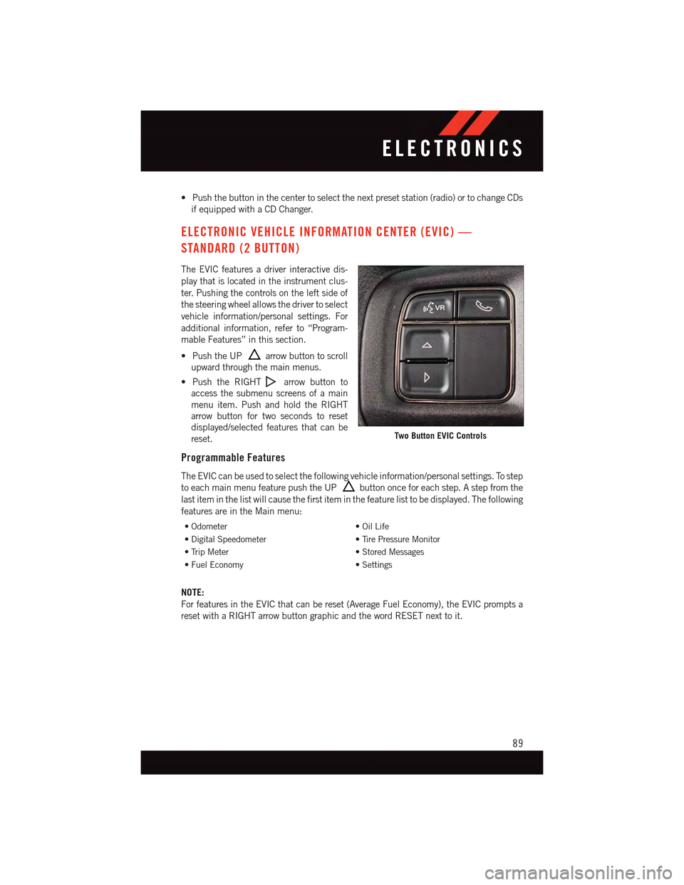
The EVIC features a driver interactive dis-
play that is located in the instrument clus-
ter. Pushing the controls on the left side of
the steering wheel allows the driver to select
vehicle information/personal settings. For
additional information, refer to “Program-
mable Features” in this section.
•PushtheUParrow button to scroll
upward through the main menus.
•PushtheRIGHTarrow button to
access the submenu screens of a main
menu item. Push and hold the RIGHT
arrow button for two seconds to reset
displayed/selected features that can be
reset.
Programmable Features
The EVIC can be used to select the following vehicle information/personal settings. To step
to each main menu feature push the UPbutton once for each step. A step from the
last item in the list will cause the first item in the feature list to be displayed. The following
features are in the Main menu:
•Odometer•OilLife
•DigitalSpeedometer•TirePressureMonitor
•TripMeter•StoredMessages
•FuelEconomy•Settings
NOTE:
For features in the EVIC that can be reset (Average Fuel Economy), the EVIC prompts a
reset with a RIGHT arrow button graphic and the word RESET next to it.
Two Button EVIC Controls
ELECTRONICS
89
Page 92 of 164
DRIVER INFORMATION DISPLAY (DID) — PREMIUM (4 BUTTON)
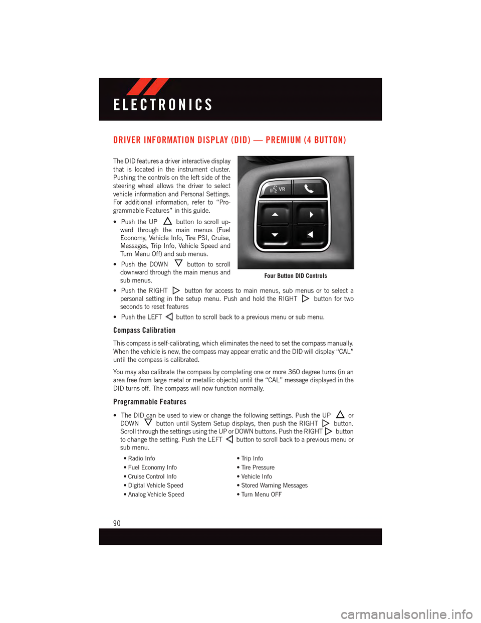
The DID features a driver interactive display
that is located in the instrument cluster.
Pushing the controls on the left side of the
steering wheel allows the driver to select
vehicle information and Personal Settings.
For additional information, refer to “Pro-
grammable Features” in this guide.
•PushtheUPbutton to scroll up-
ward through the main menus (Fuel
Economy, Vehicle Info, Tire PSI, Cruise,
Messages, Trip Info, Vehicle Speed and
Tu r n M e n u O f f ) a n d s u b m e n u s .
•PushtheDOWNbutton to scroll
downward through the main menus and
sub menus.
•PushtheRIGHTbutton for access to main menus, sub menus or to select a
personal setting in the setup menu. Push and hold the RIGHTbutton for two
seconds to reset features
•PushtheLEFTbutton to scroll back to a previous menu or sub menu.
Compass Calibration
This compass is self-calibrating, which eliminates the need to set the compass manually.
When the vehicle is new, the compass may appear erratic and the DID will display “CAL”
until the compass is calibrated.
Yo u m a y a l s o c a l i b r a t e t h e c o m p a s s b y c o m p l e t i n g o n e o r m o r e 3 6 0 d e g r e e t u r n s ( i n a n
area free from large metal or metallic objects) until the “CAL” message displayed in the
DID turns off. The compass will now function normally.
Programmable Features
•TheDIDcanbeusedtovieworchangethefollowingsettings.PushtheUPor
DOWNbutton until System Setup displays, then push the RIGHTbutton.
Scroll through the settings using the UP or DOWN buttons. Push the RIGHTbutton
to change the setting. Push the LEFTbutton to scroll back to a previous menu or
sub menu.
•RadioInfo•TripInfo
•FuelEconomyInfo•TirePressure
•CruiseControlInfo•VehicleInfo
•DigitalVehicleSpeed•StoredWarningMessages
•AnalogVehicleSpeed•TurnMenuOFF
Four Button DID Controls
ELECTRONICS
90
Page 93 of 164
DID Selectable Menu Items
The following items can be selected in the DID menu.
Full Speedometer Analog Or Digital Display
•Full Speedometer Analog Display Icon.
•Full Speedometer Digital Display Icon.
Press the UPorDOWN button until the Analog or Digital display icon is
highlighted in the DID. Press the RIGHTbutton to change the display between analog
and digital.
Vehicle Speed MPH/km/h
Press the UPorDOWN button until the Vehicle Speed icon is highlighted in the
DID. Press the RIGHTbutton to view a digital display of the current speed in MPH or
km/h. Pressing the RIGHTbutton a second time will toggle the unit of measure
between mph or km/h. Press the LEFTbutton to return to the main menu.
Vehicle Info (Customer Information Features)
Press the UPor DOWNbutton until the Vehicle Info icon is highlighted in the
DID. Press the RIGHTbutton and Coolant Temp will be displayed. Press the UP or
DOWN arrow button to scroll through the following information submenus:
•TirePressure
•CoolantTemperature
•OilTemperature
•OilLife
Fuel Economy
Press the UPorDOWN button until the Fuel Economy icon is highlighted. Press
the RIGHTbutton and the next screen will display the following:
•AverageFuelEconomy/MilesPerGallon(MPGBargraph)
•DistanceToEmpty(DTE)
•CurrentMilesPerGallon(MPG)
Navigation
Press the UPor DOWNbutton until the Navigation icon is highlighted in the
DID. Press the RIGHTbutton to display the Navigation screen in the center of the DID
display.
ELECTRONICS
91
Page 102 of 164
ROADSIDE ASSISTANCE
Dial toll-free 1-800-521-2779 for U.S. Residents or 1-800-363-4869 for Canadian
Residents.
•Provideyourname,vehicleidentificationnumber,licenseplatenumber,andyour
location, including the telephone number from which you are calling.
•Brieflydescribethenatureoftheproblemandanswerafewsimplequestions.
•Youwillbegiventhenameoftheserviceproviderandanestimatedtimeofarrival.If
you feel you are in an “unsafe situation”, please let us know. With your consent, we will
contact local police or safety authorities.
INSTRUMENT CLUSTER WARNING LIGHTS
-ElectronicStabilityControl(ESC)Activation/MalfunctionIndicatorLight
The “ESC Activation/Malfunction Indicator Light” in the instrument cluster will come on
when the ignition switch is turned to the ON/RUN position. It should go out with the
engine running. If the “ESC Activation/Malfunction Indicator Light” comes on continu-
ously with the engine running, a malfunction has been detected in the ESC system.
If this light remains on after several ignition cycles, and the vehicle has been driven
several miles (kilometers) at speeds greater than 30 mph (48 km/h), we recommend you
drive to the nearest service center and have the vehicle serviced immediately.
-TirePressureMonitoringSystem(TPMS)Light
Each tire, including the spare (if provided), should be checked monthly when cold and
inflated to the inflation pressure recommended by the vehicle manufacturer on the
vehicle placard or tire inflation pressure label. (If your vehicle has tires of a different size
than the size indicated on the vehicle placard or tire inflation pressure label, you should
determine the proper tire inflation pressure for those tires.)
As an added safety feature, your vehicle has been equipped with a tire pressure
monitoring system (TPMS) that illuminates a low tire pressure telltale when one or more
of your tires is significantly under-inflated. Accordingly, when the low tire pressure telltale
illuminates, you should stop and check your tires as soon as possible, and inflate them to
the proper pressure. Driving on a significantly under-inflated tire causes the tire to
overheat and can lead to tire failure. Under-inflation also reduces fuel efficiency and tire
tread life, and may affect the vehicle’s handling and stopping ability.
IF THE LIGHT STARTS FLASHING INDICATING A LOW TIRE PRESSURE, ADJUST THE AIR
PRESSURE IN THE LOW TIRE TO THE AIR PRESSURE SHOWN ON THE VEHICLE PLACARD OR
TIRE INFLATION PRESSURE LABEL LOCATED ON THE DRIVER'S DOOR.
WHAT TO DO IN EMERGENCIES
100
Page 103 of 164
NOTE:
AFTER INFLATION, THE VEHICLE MAY NEED TO BE DRIVEN FOR 20 MINUTES
BEFORE THE FLASHING LIGHT WILL TURN OFF.
Please note that the TPMS is not a substitute for proper tire maintenance, and it is the
driver’s responsibility to maintain correct tire pressure, even if under-inflation has not
reached the level to trigger illumination of the TPMS low tire pressure telltale.
Yo u r v e h i c l e h a s a l s o b e e n e q u i p p e d w i t h a T P M S m a l f u n c t i o n i n d i c a t o r t o i n d i c a t e w h e n
the system is not operating properly. The TPMS malfunction indicator is combined with
the low tire pressure telltale.
When the system detects a malfunction, the telltale will flash for approximately one
minute and then remain continuously illuminated. This sequence will continue upon
subsequent vehicle start-ups as long as the malfunction exists. When the malfunction
indicator is illuminated, the system may not be able to detect or signal low tire pressure
as intended. TPMS malfunctions may occur for a variety of reasons, including the
installation of replacement or alternate tires or wheels on the vehicle that prevent the
TPMS from functioning properly. Always check the TPMS malfunction telltale after
replacing one or more tires or wheels on your vehicle to ensure that the replacement or
alternate tires and wheels allow the TPMS to continue to function properly.
NOTE:
Ti r e p r e s s u r e s c h a n g e b y a p p r o x i m a t e l y 1 p s i ( 7 k P a ) p e r 1 2 ° F ( 7 ° C ) o f a i r t e m p e r a t u r e
change. Keep this in mind when checking tire pressure inside a garage, especially in the
Winter. Example: If garage temperature is 68°F (20°C) and the outside temperature is
32°F (0°C), then the cold tire inflation pressure should be increased by 3 psi (21 kPa),
which equals 1 psi (7 kPa) for every 12°F (7°C) for this outside temperature condition.
CAUTION!
The TPMS has been optimized for the original equipment tires and wheels. TPMS
pressures and warning have been established for the tire size equipped on your vehicle.
Undesirable system operation or sensor damage may result when using replacement
equipment that is not of the same size, type, and/or style. Aftermarket wheels can
cause sensor damage. Do not use tire sealant from a can, or balance beads if your
vehicle is equipped with a TPMS, as damage to the sensors may result.
WHAT TO DO IN EMERGENCIES
101
Page 116 of 164
TIRE SERVICE KIT
Yo u r v e h i c l e m a y b e e q u i p p e d w i t h a Ti r e S e r v i c e K i t .
Small punctures up to 1/4” (6 mm) in the tire tread can be sealed with the Tire Service Kit.
Foreign objects (e.g., screws or nails) should not be removed from the tire. The Tire Service
Kit can be used in outside temperatures down to approximately -4°F (-20°C).
This kit will provide a temporary tire seal, allowing you to drive your vehicle up to
100 miles (160 km) with a maximum speed of 55 mph (90 km/h).
Tire Service Kit Storage
The Tire Service Kit is located in the trunk.
Tire Service Kit Components And Operation
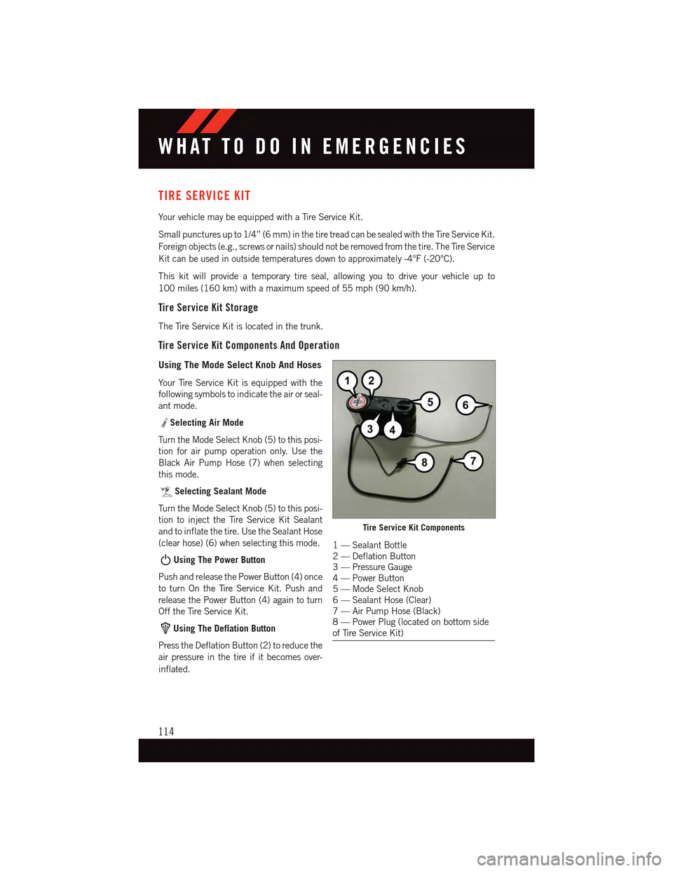
Using The Mode Select Knob And Hoses
Yo u r Ti r e S e r v i c e K i t i s e q u i p p e d w i t h t h e
following symbols to indicate the air or seal-
ant mode.
Selecting Air Mode
Tu r n t h e M o d e S e l e c t K n o b ( 5 ) t o t h i s p o s i -
tion for air pump operation only. Use the
Black Air Pump Hose (7) when selecting
this mode.
Selecting Sealant Mode
Tu r n t h e M o d e S e l e c t K n o b ( 5 ) t o t h i s p o s i -
tion to inject the Tire Service Kit Sealant
and to inflate the tire. Use the Sealant Hose
(clear hose) (6) when selecting this mode.
Using The Power Button
Push and release the Power Button (4) once
to turn On the Tire Service Kit. Push and
release the Power Button (4) again to turn
Off the Tire Service Kit.
Using The Deflation Button
Press the Deflation Button (2) to reduce the
air pressure in the tire if it becomes over-
inflated.
Tire Service Kit Components
1—SealantBottle2—DeflationButton3—PressureGauge4—PowerButton5—ModeSelectKnob6—SealantHose(Clear)7—AirPumpHose(Black)8—PowerPlug(locatedonbottomsideof Tire Service Kit)
WHAT TO DO IN EMERGENCIES
114
Page 118 of 164
(C) Injecting Tire Service Kit Sealant Into The Deflated Tire:
Always start the engine before turning ON the Tire Service Kit.
NOTE:
Manual transmission vehicles must have the parking brake engaged and the shift lever in
NEUTRAL.
After pressing the Power Button (4), the sealant (white fluid) will flow from the Sealant
Bottle (1) through the Sealant Hose (6) and into the tire.
NOTE:
Sealant may leak out through the puncture in the tire.
If the sealant (white fluid) does not flow within0–10seconds through the Sealant
Hose (6):
1. Press the Power Button (4) to turn Off the Tire Service Kit. Disconnect the Sealant
Hose (6) from the valve stem. Make sure the valve stem is free of debris. Reconnect the
Sealant Hose (6) to the valve stem. Check that the Mode Select Knob (5) is in the
Sealant Mode position and not Air Mode. Press the Power Button (4) to turn On the Tire
Service Kit.
2. Connect the Power Plug (8) to a different 12 Volt power outlet in your vehicle or
another vehicle, if available. Make sure the engine is running before turning ON the
Ti r e S e r v i c e K i t .
3. The Sealant Bottle (1) may be empty due to previous use. Call for assistance.
NOTE:
If the Mode Select Knob (5) is on Air Mode and the pump is operating, air will dispense
from the Air Pump Hose (7) only, not the Sealant Hose (6).
If the sealant (white fluid) does flow through the Sealant Hose (6):
1. Continue to operate the pump until sealant is no longer flowing through the hose
(typically takes 30 - 70 seconds). As the sealant flows through the Sealant Hose (6),
the Pressure Gauge (3) can read as high as 70 psi (4.8 Bar). The Pressure Gauge (3)
will decrease quickly from approximately 70 psi (4.8 Bar) to the actual tire pressure
when the Sealant Bottle (1) is empty.
2. The pump will start to inject air into the tire immediately after the Sealant Bottle (1)
is empty. Continue to operate the pump and inflate the tire to the pressure indicated
on the tire pressure label on the driver-side latch pillar (recommended pressure).
Check the tire pressure by looking at the Pressure Gauge (3).
WHAT TO DO IN EMERGENCIES
116
Page 119 of 164
If the tire does not inflate to at least 26 psi (1.8 Bar) pressure within 15 minutes:
The tire is too badly damaged. Do not attempt to drive the vehicle further. Call for
assistance.
NOTE:
If the tire becomes over-inflated, press the Deflation Button to reduce the tire pressure to
the recommended inflation pressure before continuing.
If the tire inflates to the recommended pressure or is at least 26 psi (1.8 Bar) pressure
within 15 minutes:
1. Press the Power Button (4) to turn off the Tire Service Kit.
2. Remove the Speed Limit sticker from the top of the Sealant Bottle (1) and place the
sticker on the instrument panel.
3. Immediately disconnect the Sealant Hose (6) from the valve stem, reinstall the cap on
the fitting at the end of the hose, and place the Tire Service Kit in the vehicle storage
location. Quickly proceed to (D) “Drive Vehicle.”
(D) Drive Vehicle:
Immediately after injecting sealant and inflating the tire, drive the vehicle 5 miles (8 km)
or 10 minutes to ensure distribution of the Tire Service Kit Sealant within the tire. Do not
exceed 55 mph (88 km/h).
(E) After Driving:
Pull over to a safe location. Refer to “Whenever You Stop to Use Tire Service Kit” before
continuing.
1. Turn the Mode Select Knob (5) to the Air Mode position.
2. Uncoil the Air Pump Hose (7) (black in color) and screw the fitting at the end of
hose (7) onto the valve stem.
3. Uncoil the power plug and insert the plug into the vehicles 12 Volt power outlet.
4. Check the pressure in the tire by reading the Pressure Gauge (3).
WHAT TO DO IN EMERGENCIES
117
Page 120 of 164
If tire pressure is less than 19 psi (1.3 Bar), the tire is too badly damaged. Do not attempt
to drive the vehicle further. Call for assistance.
If the tire pressure is 19 psi (1.3 Bar) or higher:
1. Press the Power Button (4) to turn on Tire Service Kit and inflate the tire to the pressure
indicated on the tire and loading information label on the driver-side door opening.
2. Disconnect the Tire Service Kit from the valve stem, reinstall the cap on the valve stem
and unplug from 12 Volt outlet.
3. Place the Tire Service Kit in its proper storage area in the vehicle.
4. Have the tire inspected and repaired or replaced at the earliest opportunity at an
authorized dealer or tire service center.
5. Remove the Speed Limit sticker from the instrument panel after the tire has been
repaired.
6. Replace the Sealant Bottle (1) and Sealant Hose (6) assembly at your authorized
dealer as soon as possible. Refer to “(F) Sealant Bottle and Hose Replacement.”
NOTE:
•Ifthetirebecomesover-inflated,presstheDeflationButtontoreducethetirepressure
to the recommended inflation pressure before continuing.
•Whenhavingthetireserviced,advisetheauthorizeddealerorservicecenterthatthe
tire has been sealed using the Tire Service Kit.
(F) Sealant Bottle And Hose Replacement:
1. Uncoil the Sealant Hose (6) (clear in color).
2. Locate the round Sealant Bottle release button in the recessed area under the sealant
bottle.
3. Press the Sealant Bottle release button. The Sealant Bottle (1) will pop up. Remove
the bottle and dispose of it accordingly.
4. Clean any remaining sealant from the Tire Service Kit housing.
5. Position the new Sealant Bottle (1) in the housing so that the Sealant Hose (6) aligns
with the hose slot in the front of the housing. Press the bottle into the housing. An
audible click will be heard indicating the bottle is locked into place.
6. Verify that the cap is installed on the fitting at the end of the Sealant Hose (6) and
return the hose to its storage area (located on the bottom of the air pump).
7. Return the Tire Service Kit to its storage location in the vehicle.
WHAT TO DO IN EMERGENCIES
118