crankshaft seal DODGE DURANGO 1997 1.G User Guide
[x] Cancel search | Manufacturer: DODGE, Model Year: 1997, Model line: DURANGO, Model: DODGE DURANGO 1997 1.GPages: 193, PDF Size: 5.65 MB
Page 46 of 193
Downloaded from www.Manualslib.com manuals search engine (14) Install the crankshaft damper. Tighten
damper bolt 175 N´m (130 Ft. Lbs.).
(15) Install accessory drive belt.
(16) Install the fan shroud.
(17) Install the cylinder head cover.
(18) Install the intake manifold.
(19) Install oil fill housing onto cylinder head.
(20) Refill the cooling system.
(21) Raise the vehicle.
(22) Install the exhaust pipe onto the right
exhaust manifold.
(23) Lower the vehicle.
(24) Reconnect battery negitive cable.
(25) Start the engine and check for leaks.
VALVE SPRINGS AND SEALS
REMOVAL
(1) Remove the cylinder head cover. Refer to Cyl-
inder Head Cover in this Section.
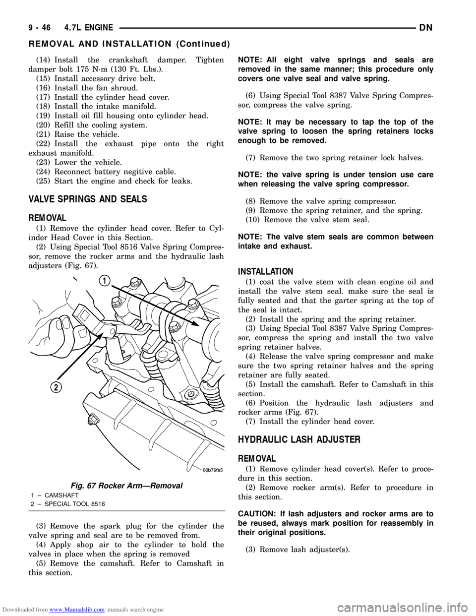
(2) Using Special Tool 8516 Valve Spring Compres-
sor, remove the rocker arms and the hydraulic lash
adjusters (Fig. 67).
(3) Remove the spark plug for the cylinder the
valve spring and seal are to be removed from.
(4) Apply shop air to the cylinder to hold the
valves in place when the spring is removed
(5) Remove the camshaft. Refer to Camshaft in
this section.NOTE: All eight valve springs and seals are
removed in the same manner; this procedure only
covers one valve seal and valve spring.
(6) Using Special Tool 8387 Valve Spring Compres-
sor, compress the valve spring.
NOTE: It may be necessary to tap the top of the
valve spring to loosen the spring retainers locks
enough to be removed.
(7) Remove the two spring retainer lock halves.
NOTE: the valve spring is under tension use care
when releasing the valve spring compressor.
(8) Remove the valve spring compressor.
(9) Remove the spring retainer, and the spring.
(10) Remove the valve stem seal.
NOTE: The valve stem seals are common between
intake and exhaust.
INSTALLATION
(1) coat the valve stem with clean engine oil and
install the valve stem seal. make sure the seal is
fully seated and that the garter spring at the top of
the seal is intact.
(2) Install the spring and the spring retainer.
(3) Using Special Tool 8387 Valve Spring Compres-
sor, compress the spring and install the two valve
spring retainer halves.
(4) Release the valve spring compressor and make
sure the two spring retainer halves and the spring
retainer are fully seated.
(5) Install the camshaft. Refer to Camshaft in this
section.
(6) Position the hydraulic lash adjusters and
rocker arms (Fig. 67).
(7) Install the cylinder head cover.
HYDRAULIC LASH ADJUSTER
REMOVAL
(1) Remove cylinder head cover(s). Refer to proce-
dure in this section.
(2) Remove rocker arm(s). Refer to procedure in
this section.
CAUTION: If lash adjusters and rocker arms are to
be reused, always mark position for reassembly in
their original positions.
(3) Remove lash adjuster(s).
Fig. 67 Rocker ArmÐRemoval
1 ± CAMSHAFT
2 ± SPECIAL TOOL 8516
9 - 46 4.7L ENGINEDN
REMOVAL AND INSTALLATION (Continued)
Page 47 of 193
Downloaded from www.Manualslib.com manuals search engine INSTALLATION
(1) Install hydraulic lash adjuster making sure
adjusters are at least partially full of oil. This can be
verified by little or no plunger travel when lash
adjuster is depressed.
(2) Install rocker arm(s). Refer to procedure in this
section.
(3) Install cylinder head cover(s). Refer to proce-
dure in this section.
CRANKSHAFT DAMPER
REMOVAL
(1) Disconnect negative cable from battery.
(2) Remove accessory drive belt. Refer to COOL-
ING SYSTEM.
(3) Drain cooling system. Refer to COOLING SYS-
TEM.
(4) Remove radiator upper hose.
(5) Remove upper fan shroud. Refer to COOLING
SYSTEM.
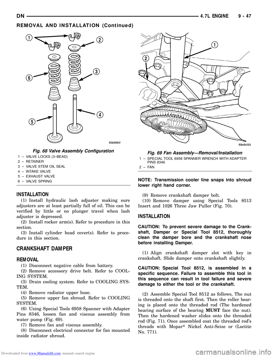
(6) Using Special Tools 6958 Spanner with Adapter
Pins 8346, loosen fan and viscous assembly from
water pump (Fig. 69).
(7) Remove fan and viscous assembly.
(8) Disconnect electrical connector for fan mounted
inside radiator shroud.NOTE: Transmission cooler line snaps into shroud
lower right hand corner.
(9) Remove crankshaft damper bolt.
(10) Remove damper using Special Tools 8513
Insert and 1026 Three Jaw Puller (Fig. 70).
INSTALLATION
CAUTION: To prevent severe damage to the Crank-
shaft, Damper or Special Tool 8512, thoroughly
clean the damper bore and the crankshaft nose
before installing Damper.
(1) Align crankshaft damper slot with key in
crankshaft. Slide damper onto crankshaft slightly.
CAUTION: Special Tool 8512, is assembled in a
specific sequence. Failure to assemble this tool in
this sequence can result in tool failure and severe
damage to either the tool or the crankshaft.
(2) Assemble Special Tool 8512 as follows, The nut
is threaded onto the shaft first. Then the roller bear-
ing is placed onto the threaded rod (The hardened
bearing surface of the bearingMUSTface the nut).
Then the hardened washer slides onto the threaded
rod (Fig. 71). Once assembled coat the threaded rod's
threads with MopartNickel Anti-Seize or (Loctite
No. 771).
Fig. 68 Valve Assembly Configuration
1 ± VALVE LOCKS (3±BEAD)
2 ± RETAINER
3 ± VALVE STEM OIL SEAL
4 ± INTAKE VALVE
5 ± EXHAUST VALVE
6 ± VALVE SPRINGFig. 69 Fan AssemblyÐRemoval/Installation
1 ± SPECIAL TOOL 6958 SPANNER WRENCH WITH ADAPTER
PINS 8346
2±FAN
DN4.7L ENGINE 9 - 47
REMOVAL AND INSTALLATION (Continued)
Page 53 of 193
Downloaded from www.Manualslib.com manuals search engine CAUTION: Overtightening the tensioner arm torxT
bolt can cause severe damage to the cylinder head.
Tighten torxTbolt to specified torque only.
(3) Install right side chain tensioner arm. Apply
MopartLock N, Seal to torxtbolt, tighten bolt to 17
N´m (150 in. lbs.).
NOTE: The silver bolts retain the guides to the cyl-
inder heads and the black bolts retain the guides to
the engine block.
(4) Install the left side chain guide. Tighten the
bolts to 28 N´m (250 in. lbs.).
CAUTION: Overtightening the tensioner arm torxT
bolt can cause severe damage to the cylinder head.
Tighten torxTbolt to specified torque only.
(5) Install left side chain tensioner arm. Apply
MopartLock N, Seal to torxtbolt, tighten bolt to 17
N´m (150 in. lbs.).
(6) Install the right side chain guide. Tighten the
bolts to 28 N´m (250 in. lbs.).
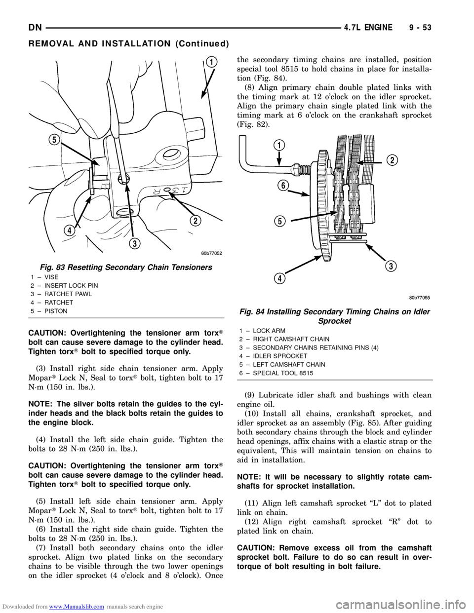
(7) Install both secondary chains onto the idler
sprocket. Align two plated links on the secondary
chains to be visible through the two lower openings
on the idler sprocket (4 o'clock and 8 o'clock). Oncethe secondary timing chains are installed, position
special tool 8515 to hold chains in place for installa-
tion (Fig. 84).
(8) Align primary chain double plated links with
the timing mark at 12 o'clock on the idler sprocket.
Align the primary chain single plated link with the
timing mark at 6 o'clock on the crankshaft sprocket
(Fig. 82).
(9) Lubricate idler shaft and bushings with clean
engine oil.
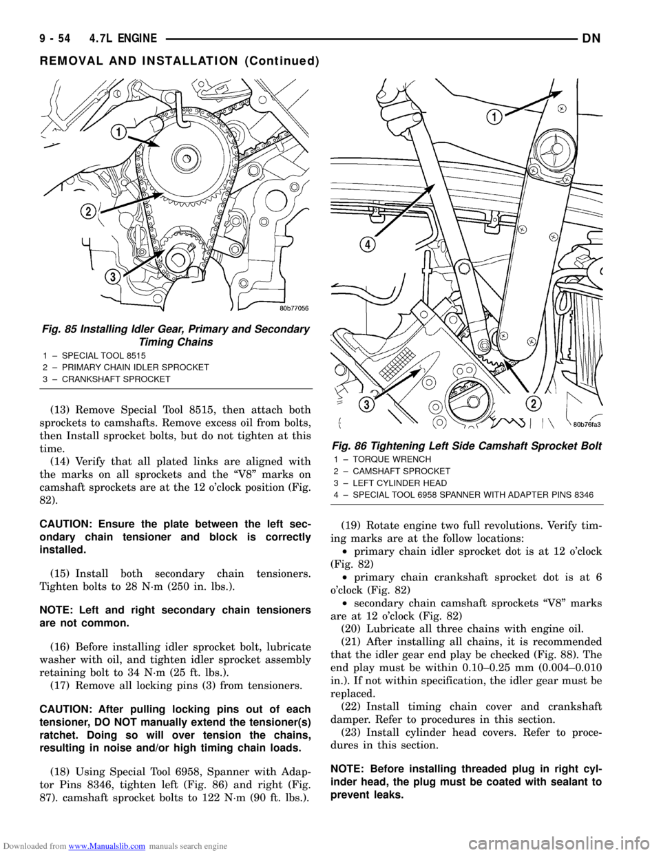
(10) Install all chains, crankshaft sprocket, and
idler sprocket as an assembly (Fig. 85). After guiding
both secondary chains through the block and cylinder
head openings, affix chains with a elastic strap or the
equivalent, This will maintain tension on chains to
aid in installation.
NOTE: It will be necessary to slightly rotate cam-
shafts for sprocket installation.
(11) Align left camshaft sprocket ªLº dot to plated
link on chain.
(12) Align right camshaft sprocket ªRº dot to
plated link on chain.
CAUTION: Remove excess oil from the camshaft
sprocket bolt. Failure to do so can result in over-
torque of bolt resulting in bolt failure.
Fig. 83 Resetting Secondary Chain Tensioners
1 ± VISE
2 ± INSERT LOCK PIN
3 ± RATCHET PAWL
4 ± RATCHET
5 ± PISTON
Fig. 84 Installing Secondary Timing Chains on Idler
Sprocket
1 ± LOCK ARM
2 ± RIGHT CAMSHAFT CHAIN
3 ± SECONDARY CHAINS RETAINING PINS (4)
4 ± IDLER SPROCKET
5 ± LEFT CAMSHAFT CHAIN
6 ± SPECIAL TOOL 8515
DN4.7L ENGINE 9 - 53
REMOVAL AND INSTALLATION (Continued)
Page 54 of 193
Downloaded from www.Manualslib.com manuals search engine (13) Remove Special Tool 8515, then attach both
sprockets to camshafts. Remove excess oil from bolts,
then Install sprocket bolts, but do not tighten at this
time.
(14) Verify that all plated links are aligned with
the marks on all sprockets and the ªV8º marks on
camshaft sprockets are at the 12 o'clock position (Fig.
82).
CAUTION: Ensure the plate between the left sec-
ondary chain tensioner and block is correctly
installed.
(15) Install both secondary chain tensioners.
Tighten bolts to 28 N´m (250 in. lbs.).
NOTE: Left and right secondary chain tensioners
are not common.
(16) Before installing idler sprocket bolt, lubricate
washer with oil, and tighten idler sprocket assembly
retaining bolt to 34 N´m (25 ft. lbs.).
(17) Remove all locking pins (3) from tensioners.
CAUTION: After pulling locking pins out of each
tensioner, DO NOT manually extend the tensioner(s)
ratchet. Doing so will over tension the chains,
resulting in noise and/or high timing chain loads.
(18) Using Special Tool 6958, Spanner with Adap-
tor Pins 8346, tighten left (Fig. 86) and right (Fig.
87). camshaft sprocket bolts to 122 N´m (90 ft. lbs.).(19) Rotate engine two full revolutions. Verify tim-
ing marks are at the follow locations:
²primary chain idler sprocket dot is at 12 o'clock
(Fig. 82)
²primary chain crankshaft sprocket dot is at 6
o'clock (Fig. 82)
²secondary chain camshaft sprockets ªV8º marks
are at 12 o'clock (Fig. 82)
(20) Lubricate all three chains with engine oil.
(21) After installing all chains, it is recommended
that the idler gear end play be checked (Fig. 88). The
end play must be within 0.10±0.25 mm (0.004±0.010
in.). If not within specification, the idler gear must be
replaced.
(22) Install timing chain cover and crankshaft
damper. Refer to procedures in this section.
(23) Install cylinder head covers. Refer to proce-
dures in this section.
NOTE: Before installing threaded plug in right cyl-
inder head, the plug must be coated with sealant to
prevent leaks.
Fig. 85 Installing Idler Gear, Primary and Secondary
Timing Chains
1 ± SPECIAL TOOL 8515
2 ± PRIMARY CHAIN IDLER SPROCKET
3 ± CRANKSHAFT SPROCKET
Fig. 86 Tightening Left Side Camshaft Sprocket Bolt
1 ± TORQUE WRENCH
2 ± CAMSHAFT SPROCKET
3 ± LEFT CYLINDER HEAD
4 ± SPECIAL TOOL 6958 SPANNER WITH ADAPTER PINS 8346
9 - 54 4.7L ENGINEDN
REMOVAL AND INSTALLATION (Continued)
Page 67 of 193
Downloaded from www.Manualslib.com manuals search engine (7) Rotate crankshaft until connecting rod journal
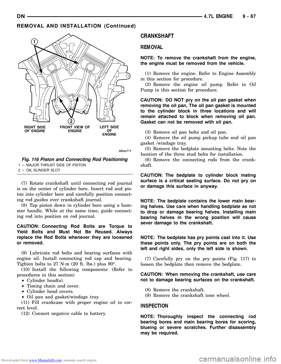
is on the center of cylinder bore. Insert rod and pis-
ton into cylinder bore and carefully position connect-
ing rod guides over crankshaft journal.
(8) Tap piston down in cylinder bore using a ham-
mer handle. While at the same time, guide connect-
ing rod into position on rod journal.
CAUTION: Connecting Rod Bolts are Torque to
Yield Bolts and Must Not Be Reused. Always
replace the Rod Bolts whenever they are loosened
or removed.
(9) Lubricate rod bolts and bearing surfaces with
engine oil. Install connecting rod cap and bearing.
Tighten bolts to 27 N´m (20 ft. lbs.) plus 90É.
(10) Install the following components: (Refer to
procedures in this section)
²Cylinder head(s).
²Timing chain and cover.
²Cylinder head covers.
²Oil pan and gasket/windage tray.
(11) Fill crankcase with proper engine oil to cor-
rect level.
(12) Connect negative cable to battery.
CRANKSHAFT
REMOVAL
NOTE: To remove the crankshaft from the engine,
the engine must be removed from the vehicle.
(1) Remove the engine. Refer to Engine Assembly
in this section for procedure.
(2) Remove the engine oil pump. Refer to Oil
Pump in this section for procedure.
CAUTION: DO NOT pry on the oil pan gasket when
removing the oil pan, The oil pan gasket is mounted
to the cylinder block in three locations and will
remain attached to block when removing oil pan.
Gasket can not be removed with oil pan.
(3) Remove oil pan bolts and oil pan.
(4) Remove the oil pump pickup tube and oil pan
gasket /windage tray.
(5) Remove the bedplate mounting bolts. Note the
location of the three stud bolts for installation.
(6) Remove the connecting rods from the crank-
shaft.
CAUTION: The bedplate to cylinder block mating
surface is a critical sealing surface. Do not pry on
or damage this surface in anyway.
NOTE: The bedplate contains the lower main bear-
ing halves. Use care when handling bedplate as not
to drop or damage bearing halves. Installing main
bearing halves in the wrong position will cause
sever damage to the crankshaft.
NOTE: The bedplate has pry points cast into it. Use
these points only. The pry points are on both the
left and right sides, only the left side is shown.
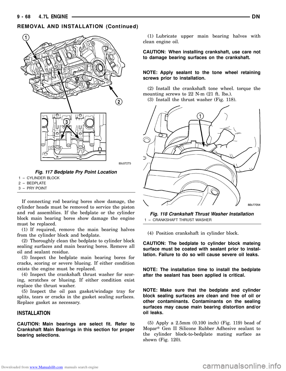
(7) Carefully pry on the pry points (Fig. 117) to
loosen the bedplate then remove the bedplate.
CAUTION: When removing the crankshaft, use care
not to damage bearing surfaces on the crankshaft.
(8) Remove the crankshaft.
(9) Remove the crankshaft tone wheel.
INSPECTION
NOTE: Thoroughly inspect the connecting rod
bearing bores and main bearing bores for scoring,
blueing or severe scratches. Further disassembly
may be required.
Fig. 116 Piston and Connecting Rod Positioning
1 ± MAJOR THRUST SIDE OF PISTON
2 ± OIL SLINGER SLOT
DN4.7L ENGINE 9 - 67
REMOVAL AND INSTALLATION (Continued)
Page 68 of 193
Downloaded from www.Manualslib.com manuals search engine If connecting rod bearing bores show damage, the
cylinder heads must be removed to service the piston
and rod assemblies. If the bedplate or the cylinder
block main bearing bores show damage the engine
must be replaced.
(1) If required, remove the main bearing halves
from the cylinder block and bedplate.
(2) Thoroughly clean the bedplate to cylinder block
sealing surfaces and main bearing bores. Remove all
oil and sealant residue.
(3) Inspect the bedplate main bearing bores for
cracks, scoring or severe blueing. If either condition
exists the engine must be replaced.
(4) Inspect the crankshaft thrust washer for scor-
ing, scratches or blueing. If either condition exist
replace the thrust washer.
(5) Inspect the oil pan gasket/windage tray for
splits, tears or cracks in the gasket sealing surfaces.
Replace gasket as necessary.
INSTALLATION
CAUTION: Main bearings are select fit. Refer to
Crankshaft Main Bearings in this section for proper
bearing selections.(1) Lubricate upper main bearing halves with
clean engine oil.
CAUTION: When installing crankshaft, use care not
to damage bearing surfaces on the crankshaft.
NOTE: Apply sealant to the tone wheel retaining
screws prior to installation.
(2) Install the crankshaft tone wheel. torque the
mounting screws to 22 N´m (21 ft. lbs.).
(3) Install the thrust washer (Fig. 118).
(4) Position crankshaft in cylinder block.
CAUTION: The bedplate to cylinder block mateing
surface must be coated with sealant prior to instal-
lation. Failure to do so will cause severe oil leaks.
NOTE: The installation time to install the bedplate
after the sealant has been applied is critical.
NOTE: Make sure that the bedplate and cylinder
block sealing surfaces are clean and free of oil or
other contaminants. Contaminants on the sealing
surfaces may cause main bearing distortion and/or
oil leaks.
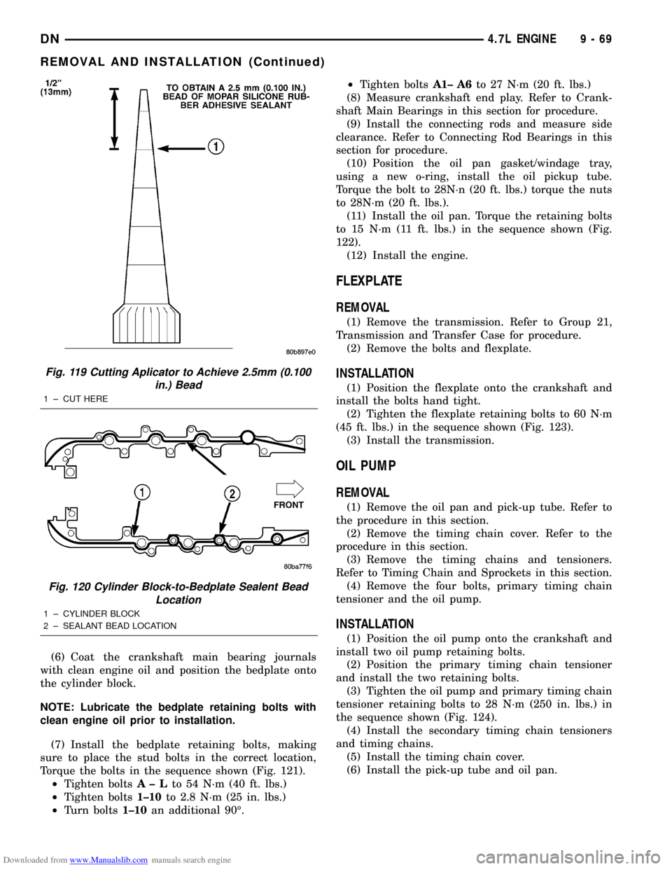
(5) Apply a 2.5mm (0.100 inch) (Fig. 119) bead of
MopartGen II Silicone Rubber Adhesive sealant to
the cylinder block-to-bedplate mating surface as
shown (Fig. 120).
Fig. 117 Bedplate Pry Point Location
1 ± CYLINDER BLOCK
2 ± BEDPLATE
3 ± PRY POINT
Fig. 118 Crankshaft Thrust Washer Installation
1 ± CRANKSHAFT THRUST WASHER
9 - 68 4.7L ENGINEDN
REMOVAL AND INSTALLATION (Continued)
Page 69 of 193
Downloaded from www.Manualslib.com manuals search engine (6) Coat the crankshaft main bearing journals
with clean engine oil and position the bedplate onto
the cylinder block.
NOTE: Lubricate the bedplate retaining bolts with
clean engine oil prior to installation.
(7) Install the bedplate retaining bolts, making
sure to place the stud bolts in the correct location,
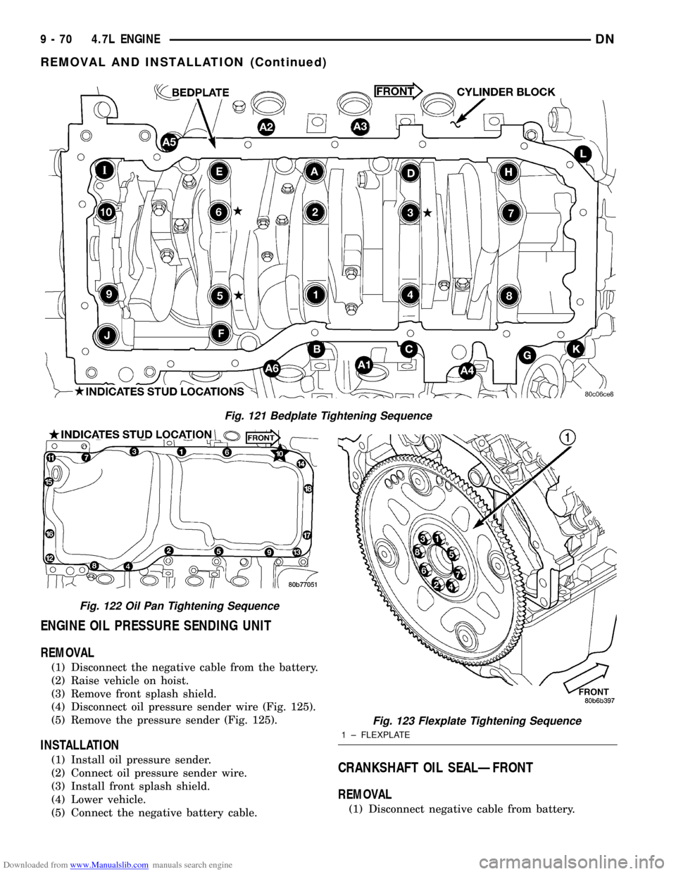
Torque the bolts in the sequence shown (Fig. 121).
²Tighten boltsA± Lto 54 N´m (40 ft. lbs.)
²Tighten bolts1±10to 2.8 N´m (25 in. lbs.)
²Turn bolts1±10an additional 90É.²Tighten boltsA1± A6to 27 N´m (20 ft. lbs.)
(8) Measure crankshaft end play. Refer to Crank-
shaft Main Bearings in this section for procedure.
(9) Install the connecting rods and measure side
clearance. Refer to Connecting Rod Bearings in this
section for procedure.
(10) Position the oil pan gasket/windage tray,
using a new o-ring, install the oil pickup tube.
Torque the bolt to 28N´n (20 ft. lbs.) torque the nuts
to 28N´m (20 ft. lbs.).
(11) Install the oil pan. Torque the retaining bolts
to 15 N´m (11 ft. lbs.) in the sequence shown (Fig.
122).
(12) Install the engine.
FLEXPLATE
REMOVAL
(1) Remove the transmission. Refer to Group 21,
Transmission and Transfer Case for procedure.
(2) Remove the bolts and flexplate.
INSTALLATION
(1) Position the flexplate onto the crankshaft and
install the bolts hand tight.
(2) Tighten the flexplate retaining bolts to 60 N´m
(45 ft. lbs.) in the sequence shown (Fig. 123).
(3) Install the transmission.
OIL PUMP
REMOVAL
(1) Remove the oil pan and pick-up tube. Refer to
the procedure in this section.
(2) Remove the timing chain cover. Refer to the
procedure in this section.
(3) Remove the timing chains and tensioners.
Refer to Timing Chain and Sprockets in this section.
(4) Remove the four bolts, primary timing chain
tensioner and the oil pump.
INSTALLATION
(1) Position the oil pump onto the crankshaft and
install two oil pump retaining bolts.
(2) Position the primary timing chain tensioner
and install the two retaining bolts.
(3) Tighten the oil pump and primary timing chain
tensioner retaining bolts to 28 N´m (250 in. lbs.) in
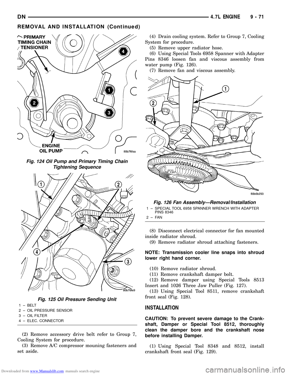
the sequence shown (Fig. 124).
(4) Install the secondary timing chain tensioners
and timing chains.
(5) Install the timing chain cover.
(6) Install the pick-up tube and oil pan.
Fig. 119 Cutting Aplicator to Achieve 2.5mm (0.100
in.) Bead
1 ± CUT HERE
Fig. 120 Cylinder Block-to-Bedplate Sealent Bead
Location
1 ± CYLINDER BLOCK
2 ± SEALANT BEAD LOCATION
DN4.7L ENGINE 9 - 69
REMOVAL AND INSTALLATION (Continued)
Page 70 of 193
Downloaded from www.Manualslib.com manuals search engine ENGINE OIL PRESSURE SENDING UNIT
REMOVAL
(1) Disconnect the negative cable from the battery.
(2) Raise vehicle on hoist.
(3) Remove front splash shield.
(4) Disconnect oil pressure sender wire (Fig. 125).
(5) Remove the pressure sender (Fig. 125).
INSTALLATION
(1) Install oil pressure sender.
(2) Connect oil pressure sender wire.
(3) Install front splash shield.
(4) Lower vehicle.
(5) Connect the negative battery cable.CRANKSHAFT OIL SEALÐFRONT
REMOVAL
(1) Disconnect negative cable from battery.
Fig. 121 Bedplate Tightening Sequence
Fig. 122 Oil Pan Tightening Sequence
Fig. 123 Flexplate Tightening Sequence
1 ± FLEXPLATE
9 - 70 4.7L ENGINEDN
REMOVAL AND INSTALLATION (Continued)
Page 71 of 193
Downloaded from www.Manualslib.com manuals search engine (2) Remove accessory drive belt refer to Group 7,
Cooling System for procedure.
(3) Remove A/C compressor mouning fasteners and
set aside.(4) Drain cooling system. Refer to Group 7, Cooling
System for procedure.
(5) Remove upper radiator hose.
(6) Using Special Tools 6958 Spanner with Adapter
Pins 8346 loosen fan and viscous assembly from
water pump (Fig. 126).
(7) Remove fan and viscous assembly.
(8) Disconnect electrical connector for fan mounted
inside radiator shroud.
(9) Remove radiator shroud attaching fasteners.
NOTE: Transmission cooler line snaps into shroud
lower right hand corner.
(10) Remove radiator shroud.
(11) Remove crankshaft damper bolt.
(12) Remove damper using Special Tools 8513
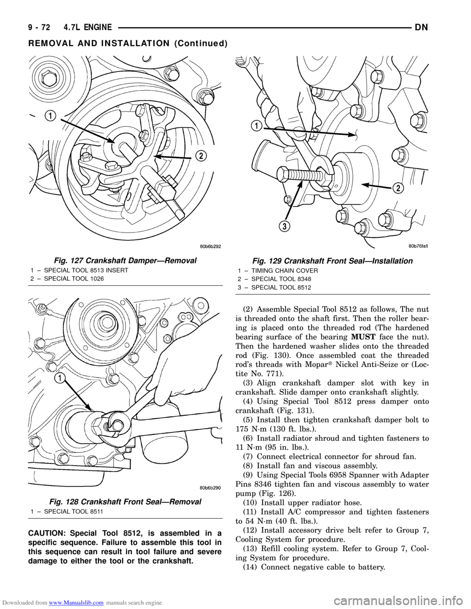
Insert and 1026 Three Jaw Puller (Fig. 127).
(13) Using Special Tool 8511, remove crankshaft
front seal (Fig. 128).
INSTALLATION
CAUTION: To prevent severe damage to the Crank-
shaft, Damper or Special Tool 8512, thoroughly
clean the damper bore and the crankshaft nose
before installing Damper.
(1) Using Special Tool 8348 and 8512, install
crankshaft front seal (Fig. 129).
Fig. 124 Oil Pump and Primary Timing Chain
Tightening Sequence
Fig. 125 Oil Pressure Sending Unit
1 ± BELT
2 ± OIL PRESSURE SENSOR
3 ± OIL FILTER
4 ± ELEC. CONNECTOR
Fig. 126 Fan AssemblyÐRemoval/Installation
1 ± SPECIAL TOOL 6958 SPANNER WRENCH WITH ADAPTER
PINS 8346
2±FAN
DN4.7L ENGINE 9 - 71
REMOVAL AND INSTALLATION (Continued)
Page 72 of 193
Downloaded from www.Manualslib.com manuals search engine CAUTION: Special Tool 8512, is assembled in a
specific sequence. Failure to assemble this tool in
this sequence can result in tool failure and severe
damage to either the tool or the crankshaft.(2) Assemble Special Tool 8512 as follows, The nut
is threaded onto the shaft first. Then the roller bear-
ing is placed onto the threaded rod (The hardened
bearing surface of the bearingMUSTface the nut).
Then the hardened washer slides onto the threaded
rod (Fig. 130). Once assembled coat the threaded
rod's threads with MopartNickel Anti-Seize or (Loc-
tite No. 771).
(3) Align crankshaft damper slot with key in
crankshaft. Slide damper onto crankshaft slightly.
(4) Using Special Tool 8512 press damper onto
crankshaft (Fig. 131).
(5) Install then tighten crankshaft damper bolt to
175 N´m (130 ft. lbs.).
(6) Install radiator shroud and tighten fasteners to
11 N´m (95 in. lbs.).
(7) Connect electrical connector for shroud fan.
(8) Install fan and viscous assembly.
(9) Using Special Tools 6958 Spanner with Adapter
Pins 8346 tighten fan and viscous assembly to water
pump (Fig. 126).
(10) Install upper radiator hose.
(11) Install A/C compressor and tighten fasteners
to 54 N´m (40 ft. lbs.).
(12) Install accessory drive belt refer to Group 7,
Cooling System for procedure.
(13) Refill cooling system. Refer to Group 7, Cool-
ing System for procedure.
(14) Connect negative cable to battery.
Fig. 127 Crankshaft DamperÐRemoval
1 ± SPECIAL TOOL 8513 INSERT
2 ± SPECIAL TOOL 1026
Fig. 128 Crankshaft Front SealÐRemoval
1 ± SPECIAL TOOL 8511
Fig. 129 Crankshaft Front SealÐInstallation
1 ± TIMING CHAIN COVER
2 ± SPECIAL TOOL 8348
3 ± SPECIAL TOOL 8512
9 - 72 4.7L ENGINEDN
REMOVAL AND INSTALLATION (Continued)