air DODGE DURANGO 1998 1.G User Guide
[x] Cancel search | Manufacturer: DODGE, Model Year: 1998, Model line: DURANGO, Model: DODGE DURANGO 1998 1.GPages: 193, PDF Size: 5.65 MB
Page 19 of 193

Downloaded from www.Manualslib.com manuals search engine (6) Identify the fluid in the cylinders (i.e. coolant,
fuel, oil, etc.).
(7) Make sure all fluid has been removed from the
cylinders.
(8) Repair engine or components as necessary to
prevent this problem from occurring again.
(9) Squirt engine oil into the cylinders to lubricate
the walls. This will prevent damage on restart.
(10) Install new spark plugs.
(11) Drain engine oil. Remove and discard the oil
filter.
(12) Install the drain plug. Tighten the plug to 34
N´m (25 ft. lbs.) torque.
(13) Install a new oil filter.
(14) Fill engine crankcase with the specified
amount and grade of oil.
(15) Connect the negative cable to the battery.
(16) Start the engine and check for any leaks.
VALVE SERVICE
REFACING
NOTE: Valve seats that are worn or burned can be
reworked, provided that correct angle and seat
width are maintained. Otherwise the cylinder head
must be replaced.
NOTE: When refacing valves and valve seats, it is
important that the correct size valve guide pilot be
used for reseating stones. A true and complete sur-
face must be obtained.
(1) Using a suitable dial indicator measure the
center of the valve seat Total run out must not
exceed 0.051 mm (0.002 in).
(2) Apply a small amount of Prussian blue to the
valve seat, insert the valve into the cylinder head,
while applying light pressure on the valve rotate the
valve. Remove the valve and examine the valve face.
If the blue is transferred below the top edge of the
valve face, lower the valve seat using a 15 degree
stone. If the blue is transferred to the bottom edge of
the valve face, raise the valve seat using a 65 degree
stone.
(3) When the seat is properly positioned the width
of the intake seat must be 1.75 ± 2.36 mm (0.0689 ±
0.0928 in.) and the exhaust seat must be 1.71 ± 2.32
mm (0.0673 ± 0.0911 in.).
(4) Check the valve spring installed height after
refacing the valve and seat. The installed height for
both intake and exhaust valve springs must not
exceed 41.44 mm (1.6315 in.).
(5) The valve seat and valve face must maintain a
face angle of 44.5 ± 45 degrees angle.
ENGINE TIMINGÐVERIFICATION
CAUTION: The 4.7L is a non free-wheeling design
engine. Therefore, correct engine timing is critical.
NOTE: Components referred to as left hand or right
hand are as viewed from the drivers position inside
the vehicle.
NOTE: The blue link plates on the chains and the
dots on the camshaft drive sprockets may not line
up during the timing verification procedure. The
blue link plates are lined up with the sprocket dots
only when re-timing the complete timing drive.
Once the timing drive is rotated blue link-to-dot
alignment is no longer valid.
Engine base timing can be verified by the following
procedure:
(1) Remove the cylinder head covers. Refer to the
procedure in this section.
(2) Using a mirror, locate the TDC arrow on the
front cover (Fig. 11). Rotate the crankshaft until the
mark on the crankshaft damper is aligned with the
TDC arrow on the front cover. The engine is now at
TDC.
Fig. 10 Valve Assembly Configuration
1 ± VALVE LOCKS (3±BEAD)
2 ± RETAINER
3 ± VALVE STEM OIL SEAL
4 ± INTAKE VALVE
5 ± EXHAUST VALVE
6 ± VALVE SPRING
DN4.7L ENGINE 9 - 19
SERVICE PROCEDURES (Continued)
Page 20 of 193

Downloaded from www.Manualslib.com manuals search engine (3) Note the location of the V8 mark stamped into
the camshaft drive gears (Fig. 12). If the V8 mark on
each camshaft drive gear is at the twelve o'clock posi-
tion, the engine is at TDC on the exhaust stroke. If
the V8 mark on each gear is at the six o'clock posi-
tion, the engine is at TDC on the compression stroke.
(4) If both of the camshaft drive gears are off in
the same or opposite directions, the primary chain or
both secondary chains are at fault. Refer to Timing
Chain and Sprockets procedure in this section.
(5) If only one of the camshaft drive gears is off
and the other is correct, the problem is confined to
one secondary chain. Refer to Single camshaft tim-
ing, in this procedure.
(6) If both camshaft drive gear V8 marks are at
the twelve o'clock or the six o' clock position the
engine base timing is correct. Reinstall the cylinder
head covers.
SINGLE CAMSHAFT TIMING
NOTE: to adjust the timing on one camshaft, pre-
form the following procedure.
(1) Using Chain Tensioner Wedge, special tool
8350, stabilize the secondary chain drive. For refer-
ence purposes, mark the chain-to-sprocket position
(Fig. 13).
(2) Remove the camshaft drive gear retaining bolt.
(3) Carefully remove the camshaft drive gear from
the camshaft.
(4) Re-index the camshaft drive gear in the chain
until the V8 mark is at the same position as the V8
mark on the opposite camshaft drive gear.
NOTE: When gripping the camshaft, place the pli-
ers on the tube portion of the camshaft only. Do not
grip the lobes or the sprocket areas.
(5) Using a suitable pair of adjustable pliers,
rotate the camshaft until the alignment dowel on the
camshaft is aligned with the slot in the camshaft
drive gear (Fig. 14).
CAUTION: Remove excess oil from camshaft
sprocket retaining bolt before reinstalling bolt. Fail-
ure to do so may cause over-torqueing of bolt
resulting in bolt failure.
(6) Position the camshaft drive gear onto the cam-
shaft, remove oil from bolt then install the retaining
bolt. Using Special Tools, Spanner Wrench 6958 with
Adapter Pins 8346 and a suitable torque wrench,
Tighten retaining bolt to 122N´m (90 ft. Lbs.) (Fig.
15) (Fig. 16).
(7) Remove special tool 8350.
(8) Rotate the crankshaft two full revolutions, then
reverify that the camshaft drive gear V8 marks are
in fact aligned.
(9) Install the cylinder head covers. Refer to Cylin-
der Head Cover in this section.
Fig. 11 Engine Top Dead Center (TDC) Indicator
Mark
1 ± TIMING CHAIN COVER
2 ± CRANKSHAFT TIMING MARKS
9 - 20 4.7L ENGINEDN
SERVICE PROCEDURES (Continued)
Page 27 of 193
Downloaded from www.Manualslib.com manuals search engine (9) Repeat the Plastigage measurement to verify
your bearing selection prior to final assembly.
(10) Once you have selected the proper insert,
install the insert and cap. Tighten the connecting rod
bolts to 27 N´m (20 ft. lbs.) plus a 90É turn.
Slide snug-fitting feeler gauge between the con-
necting rod and crankshaft journal flange (Fig. 30).
Refer to Engine Specifications for the proper clear-
ance. Replace the connecting rod if the side clearance
is not within specification.
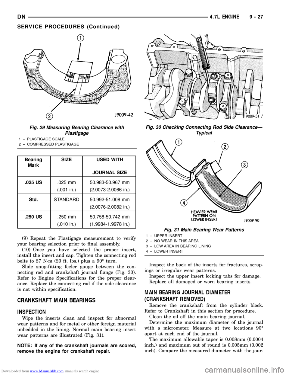
CRANKSHAFT MAIN BEARINGS
INSPECTION
Wipe the inserts clean and inspect for abnormal
wear patterns and for metal or other foreign material
imbedded in the lining. Normal main bearing insert
wear patterns are illustrated (Fig. 31).
NOTE: If any of the crankshaft journals are scored,
remove the engine for crankshaft repair.Inspect the back of the inserts for fractures, scrap-
ings or irregular wear patterns.
Inspect the upper insert locking tabs for damage.
Replace all damaged or worn bearing inserts.
MAIN BEARING JOURNAL DIAMETER
(CRANKSHAFT REMOVED)
Remove the crankshaft from the cylinder block.
Refer to Crankshaft in this section for procedure.
Clean the oil off the main bearing journal.
Determine the maximum diameter of the journal
with a micrometer. Measure at two locations 90É
apart at each end of the journal.
The maximum allowable taper is 0.008mm (0.0004
inch.) and maximum out of round is 0.005mm (0.002
inch). Compare the measured diameter with the jour-
Fig. 29 Measuring Bearing Clearance with
Plastigage
1 ± PLASTIGAGE SCALE
2 ± COMPRESSED PLASTIGAGE
Bearing
MarkSIZE USED WITH
JOURNAL SIZE
.025 US.025 mm 50.983-50.967 mm
(.001 in.) (2.0073-2.0066 in.)
Std.STANDARD 50.992-51.008 mm
(2.0076-2.0082 in.)
.250 US.250 mm 50.758-50.742 mm
(.010 in.) (1.9984-1.9978 in.)
Fig. 30 Checking Connecting Rod Side ClearanceÐ
Typical
Fig. 31 Main Bearing Wear Patterns
1 ± UPPER INSERT
2 ± NO WEAR IN THIS AREA
3 ± LOW AREA IN BEARING LINING
4 ± LOWER INSERT
DN4.7L ENGINE 9 - 27
SERVICE PROCEDURES (Continued)
Page 31 of 193

Downloaded from www.Manualslib.com manuals search engine ENGINE ASSEMBLY
REMOVAL
NOTE: This procedure applies to both the 4X2 and
4X4 vehicles, steps that apply to the 4X4 vehicle
only, are identified.
(1) Disconnect the battery negative and positive
cables.
(2) Remove the battery and the battery tray. Refer
to BATTERY.
(3) Raise vehicle on hoist.
(4) Remove exhaust crossover pipe from exhaust
manifolds. Refer to EXHAUST SYSTEM.
(5)4X4 vehiclesDisconnect axle vent tube from
left side engine mount.
(6) Remove the through bolt retaining nut and bolt
from both the left and right side engine mounts (Fig.
40) (Fig. 41).
(7)4X4 vehiclesRemove locknut from left and
right side engine mount brackets (Fig. 41).
(8) Disconnect two ground straps from the lower
left hand side and one ground strap from the lower
right hand side of the engine.
(9) Disconnect crankshaft position sensor. (Fig. 43)
NOTE: The following step applies to 4X4 vehicles
equipped with automatic transmission only.
(10)4X4 vehiclesRemove the axle isolator
bracket from the engine, transmission and the axle
(Fig. 42).
(11) Remove structural cover. Refer to Structural
Cover in this section for procedure.
(12) Remove starter. Refer to STARTING SYS-
TEM.
(13) Drain cooling system. Refer to COOLING
SYSTEM.
(14) Remove torque converter bolts (Automatic
Transmission Only). Refer to TRANSMISSION.
(15) Remove transmission to engine mounting
bolts.
(16) Disconnect the engine block heater power
cable from the block heater, if equipped.(17) Lower vehicle.
(18) Remove throttle body resonator assembly and
air inlet hose.
(19) Disconnect throttle and speed control cables.
(20) Disconnect tube from both the left and right
side crankcase breathers (Fig. 44). Remove breathers
(21) Discharge A/C system. Refer to HEATING and
AIR CONDITIONING.
(22) Remove A/C compressor.
(23) Remove shroud, fan assemblies and accessory
drive belt. Refer to COOLING SYSTEM.
(24) Disconnect transmission oil cooler lines at the
radiator.
(25) Disconnect radiator upper and lower hoses.
Refer to COOLING SYSTEM.
(26) Remove radiator, A/C condenser and transmis-
sion oil cooler as an assembly. Refer to COOLING
SYSTEM.
(27) Remove generator.
(28) Disconnect the two heater hoses from the tim-
ing chain cover and heater core.
(29) Unclip and remove heater hoses and tubes
from the intake manifold (Fig. 45).
(30) Disconnect engine harness at the following
points :
²Intake air temperature (IAT) sensor (Fig. 46)
²Fuel Injectors
SEQUENCE ITEM TORQUE
1BOLT 54 N´m
(Qty 4) (40 ft. lbs.)
2BOLT 54 N´m
(Qty 2) (40 ft. lbs.)
3BOLT 54 N´m
(Qty 2) (40 ft. lbs.)
Fig. 40 Engine Mount Through Bolt and Nut
Removal / InstallationÐ4X2 Vehicles
1 ± LOCKNUT AND WASHER
2 ± ENGINE MOUNT/INSULATOR
3 ± THROUGH BOLT
4 ± FRAME
DN4.7L ENGINE 9 - 31
REMOVAL AND INSTALLATION (Continued)
Page 32 of 193

Downloaded from www.Manualslib.com manuals search engine ²Throttle Position (TPS) Switch
²Idle Air Control (IAC) Motor
²Engine Oil Pressure Switch
²Engine Coolant Temperature (ECT) Sensor
²Manifold absolute pressure (MAP) Sensor
²Camshaft Position (CMP) Sensor
²Coil Over Plugs
(31) Disconnect the vacuum lines at the throttle
body and intake manifold.
(32) Release fuel rail pressure then disconnect the
fuel supply quick connect fitting at the fuel rail.
Refer toFUEL SYSTEM for procedure.
(33) Remove power steering pump and position out
of the way.
(34) Install Special Tools 8400 Lifting Studs, into
the cylinder heads.
(35) Install Engine Lifting Fixture Special Tool
8347 (Fig. 47) following these steps.
²Holding the lifting fixture at a slight angle, slide
the large bore in the front plate over the hex portion
of the lifting stud.
²Position the two remaining fixture arms onto
the two Special Tools 8400 Lifting Studs, in the cyl-
inder heads.
²Pull foward and upward on the lifting fixture so
that the lifting stud rest in the slotted area below the
large bore.²Secure the lifting fixture to the three studs
using three 7/16 ± 14 N/C locknuts.
²Make sure the lifting loop in the lifting fixture is
in the last hole (closest to the throttle body) to min-
imize the angle of engine during removal.
(36) Disconnect body ground strap at the right side
cowl (Fig. 48).
(37) Disconnect body ground strap at the left side
cowl (Fig. 49).
NOTE: It will be necessary to support the transmis-
sion in order to remove the engine.
(38) Position a suitable jack under the transmis-
sion.
(39) Remove engine from the vehicle.
INSTALLATION
(1) Position engine in the vehicle.
Position both the left and right side engine mount
brackets and install the through bolts and nuts.
Tighten nuts to4X2 vehicles95 N´m (70 ft. lbs.).
4X4 vehicles102 N´m (75 ft. lbs.).
Fig. 41 Engine Mount Through Bolt and Nut
Removal / InstallationÐ4X4 Vehicles
1 ± ENGINE MOUNT BRACKET (2)
2 ± THROUGH BOLT (2)
3 ± LOCKNUT AND WASHER (2)
4 ± ENGINE ISOLATOR TO ENGINE MOUNT BRACKET STUD (2)
5 ± LOCKNUT (2)
Fig. 42 Axle Isolator Bracket Removal /
InstallationÐ4X4 Vehicles With Automatic
Transmission
1 ± TRANSMISSION
2 ± AXLE ISOLATOR BRACKET
3 ± FRONT AXLE 4X4 VEHICLES
4 ± BOLTS
5 ± ENGINE
9 - 32 4.7L ENGINEDN
REMOVAL AND INSTALLATION (Continued)
Page 33 of 193

Downloaded from www.Manualslib.com manuals search engine (2)4X4 vehiclesInstall locknuts onto the engine
mount brackets. Tighten locknuts to 41 N´m (30 ft.
lbs.).
(3) Remove jack from under the transmission.
(4) Remove Engine Lifting Fixture Special Tool
8347 (Fig. 47).
(5) Remove Special Tools 8400 Lifting Studs.
(6) Position generator wiring behind the oil dip-
stick tube, then install the oil dipstick tube upper
mounting bolt.
(7) Connect both left and right side body ground
straps.(8) Install power steering pump.
(9) Connect fuel supply line quick connect fitting.
(10) Connect the vacuum lines at the throttle body
and intake manifold.
(11) Connect engine harness at the following
points (Fig. 46) :
²Intake Air Temperature (IAT) Sensor
²Idle Air Control (IAC) Motor
²Fuel Injectors
²Throttle Position (TPS) Switch
²Engine Oil Pressure Switch
²Engine Coolant Temperature (ECT) Sensor
²Manifold Absolute Pressure (MAP) Sensor
²Camshaft Position (CMP) Sensor
²Coil Over Plugs
(12) Position and install heater hoses and tubes
onto intake manifold.
(13) Install the heater hoses onto the heater core
and the engine front cover.
(14) Install generator.
(15) Install A/C condenser, radiator and transmis-
sion oil cooler as an assembly.
(16) Connect radiator upper and lower hoses.
(17) Connect the transmission oil cooler lines to
the radiator.
(18) Install accessory drive belt, fan assembly and
shroud.
(19) Install A/C compressor. Tighten the A/C com-
pressor and generator M10 mounting bolts 40±68N´M
(30±50 ft. lbs.) and the M8 bolts 22±34 N´m (200±300
in. lbs.).
Fig. 43 Crankshaft Position Sensor
1 ± CRANKSHAFT POSITION SENSOR
2 ± CYLINDER HEAD COVER
3 ± CAMSHAFT POSITION SENSOR
4 ± RIGHT SIDE CYLINDER BLOCK
Fig. 44 Crankcase Breather Connection Points
1 ± CRANKCASE BREATHERS
Fig. 45 Heater Hoses and Tubes Removal /
Installation
1 ± HEATER HOSES AND TUBES
2 ± ROUTING/RETAINING CLIPS
DN4.7L ENGINE 9 - 33
REMOVAL AND INSTALLATION (Continued)
Page 34 of 193

Downloaded from www.Manualslib.com manuals search engine (20) Install both breathers. Connect tube to both
crankcase breathers (Fig. 44).
(21) Connect throttle and speed control cables.
(22) Install throttle body resonator assembly and
air inlet hose. Tighten clamps 4 N´m (35 in. lbs.).
(23) Raise vehicle.
(24) Install transmission to engine mounting bolts.
Tighten the bolts to 41 N´m (30 ft. lbs.).
(25) Install torque converter bolts (Automatic
Transmission Only).
(26) Connect crankshaft position sensor (Fig. 43).
(27)4X4 vehiclesPosition and install the axle
isolator bracket onto the axle, transmission and
engine block. Tighten bolts to specification. Refer to
Specifications in this section.
(28) Install starter.
CAUTION: The structural cover requires a specific
torque sequence. Failure to follow this sequence
may cause severe damage to the cover.(29) Install structural cover. Refer to Structural
Cover in this section.
(30) Install exhaust crossover pipe.
(31) Install engine block heater power cable, If
equipped.
(32)4X4 vehiclesConnect axle vent tube to left
side engine mount.
(33) Lower vehicle.
(34) Check and fill engine oil.
(35) Recharge the A/C system.
(36) Refill the engine cooling system. Refer to
COOLING SYSTEM.
(37) Install the battery tray and battery.
(38) Connect the battery positive and negative
cables.
(39) Start the engine and check for leaks.
Fig. 46 Throttle Body Connection Points
1 ± THROTTLE BODY
2 ± TPS
3 ± IAC MOTOR
4 ± IAT SENSOR
5 ± MOUNTING SCREWS
Fig. 47 Engine Lifting Fixture Attachment Locations
1 ± ATTACHING LOCATION
2 ± ADJUSTABLE HOOK
3 ± SPECIAL TOOL 8347 ENGINE LIFT FIXTURE
4 ± ATTACHING LOCATIONS
9 - 34 4.7L ENGINEDN
REMOVAL AND INSTALLATION (Continued)
Page 35 of 193

Downloaded from www.Manualslib.com manuals search engine INTAKE MANIFOLD
REMOVAL
(1) Disconnect negative cable from battery.
(2) Remove resonator assembly and air inlet hose.
(3) Disconnect throttle and speed control cables.
(4) Disconnect electrical connectors for the follow-
ing components: Refer to FUEL SYSTEM for compo-
nent locations.
²Manifold Absolute Pressure (MAP) Sensor
²Intake Air Temperature (IAT) Sensor
²Throttle Position (TPS) Sensor
²Coolant Temperature (CTS) Sensor
²Idle Air Control (IAC) Motor
(5) Disconnect vapor purge hose, brake booster
hose, speed control servo hose, positive crankcase
ventilation (PCV) hose.
(6) Disconnect generator electrical connections.
(7) Disconnect air conditioning compressor electri-
cal connections.
(8) Disconnect left and right radio suppressor
straps.
(9) Disconnect and remove ignition coil towers.
(10) Remove top oil dipstick tube retaining bolt
and ground strap.
(11) Bleed fuel system. Refer to FUEL SYSTEM.
(12) Remove fuel rail.
(13) Remove throttle body assembly and mounting
bracket.
(14) Drain cooling system below coolant tempera-
ture level. Refer to COOLING SYSTEM.
(15) Remove the heater hoses from the engine
front cover and the heater core.
(16) Unclip and remove heater hoses and tubes
from intake manifold (Fig. 50).
(17) Remove coolant temperature sensor. Refer to
FUEL SYSTEM.
(18) Remove intake manifold retaining fasteners in
reverse order of tightening sequence (Fig. 51).
(19) Remove intake manifold.
INSTALLATION
(1) Install intake manifold gaskets.
(2) Install intake manifold.
(3) Install intake manifold retaining bolts and
tighten in sequence shown in (Fig. 51) to 12 N´m
(105 in. lbs.).
(4) Install left and right radio suppressor straps.
(5) Install throttle body assembly.
(6) Install throttle cable bracket.
(7) Connect throttle cable and speed control cable
to throttle body.
(8) Install fuel rail.
(9) Install ignition coil towers.
Fig. 48 Body Ground StrapÐRight Side Removal /
Installation
1 ± NUT
2 ± A/C ACCUMULATOR
3 ± GROUND STRAP
Fig. 49 Body Ground StrapÐLeft Side Removal /
Installation
1 ± NUT
2 ± GROUND STRAP
3 ± BRAKE BOOSTER
DN4.7L ENGINE 9 - 35
REMOVAL AND INSTALLATION (Continued)
Page 36 of 193

Downloaded from www.Manualslib.com manuals search engine (10) Position and install heater hoses and tubes
onto intake manifold.
(11) Install the heater hoses to the heater core and
engine front cover.(12) Connect electrical connectors for the following
components:
²Manifold Absolute Pressure (MAP) Sensor
²Intake Air Temperature (IAT) Sensor
²Throttle Position (TPS) Sensor
²Coolant Temperature (CTS) Sensor
²Idle Air Control (IAC) Motor
²Ignition coil towers
²Fuel injectors
(13) Install top oil dipstick tube retaining bolt and
ground strap.
(14) Connect generator electrical connections.
(15) Connect Vapor purge hose, Brake booster
hose, Speed control servo hose, Positive crankcase
ventilation (PCV) hose.
(16) Fill cooling system.
(17) Install resonator assembly and air inlet hose.
(18) Connect negative cable to battery.
EXHAUST MANIFOLDS
RIGHT EXHAUST MANIFOLD
REMOVAL
(1) Disconnect negative cable for battery.
(2) Remove air cleaner assembly, resonator assem-
bly and air inlet hose.
(3) Remove accessory drive belt. Refer to COOL-
ING SYSTEM.
(4) Remove A/C compressor from mounting and set
aside.
(5) Remove A/C accumulator support bracket fas-
tener.
(6) Drain coolant below heater hose level. Refer to
COOLING SYSTEM.
(7) Remove heater hoses at engine.
(8) Remove fasteners attaching exhaust manifold
heat shield.
(9) Remove heat shield.
(10) Remove upper exhaust manifold attaching fas-
teners.
(11) Raise vehicle on hoist.
(12) Disconnect exhaust pipe from manifold.
(13) Remove fasteners attaching starter. Move
starter aside.
(14) Remove lower exhaust manifold attaching fas-
teners.
(15) Remove exhaust manifold and gasket (Fig.
52). Manifold is removed from below the engine com-
partment.
Fig. 50 Heater Hoses and Tubes Removal /
Installation
1 ± HEATER HOSES AND TUBES
2 ± ROUTING/RETAINING CLIPS
Fig. 51 Intake Manifold Tightening Sequence
9 - 36 4.7L ENGINEDN
REMOVAL AND INSTALLATION (Continued)
Page 38 of 193

Downloaded from www.Manualslib.com manuals search engine (9) Install A/C compressor and fasteners.
(10) Install accessory drive belt.
(11) Install air cleaner assembly, resonator assem-
bly and air inlet hose.
(12) Install battery and connect cables.
(13) Fill cooling system.
LEFT EXHAUST MANIFOLD
REMOVAL
(1) Disconnect negative cable for battery.
(2) Hoist vehicle.
(3) Disconnect exhaust pipe at manifold.
(4) Lower vehicle.
(5) Remove the front two exhaust heat shield
retaining fasteners. Raise vehicle and remove the
fasteners at rear of heat shield.
(6) Remove heat shield (Fig. 53).
(7) Lower vehicle and remove the upper exhaust
manifold retaining bolts (Fig. 53).
(8) Raise vehicle and remove the lower exhaust
manifold retaining bolts (Fig. 53).
(9) Remove exhaust manifold and gasket (Fig. 53).
Manifold is removed from below the engine compart-
ment.
INSTALLATION
(1) Install exhaust manifold and gasket from below
engine compartment.
(2) Install lower exhaust manifold fasteners (Fig.
53). DO NOT tighten until all fasteners are in place.
(3) Lower vehicle and install upper exhaust mani-
fold fasteners (Fig. 53). Tighten all manifold bolts
starting at center and working outward to 25 N´m
(18 ft. lbs.).
CAUTION: Over tightening heat shield fasteners,
may cause shield to distort and/or crack.
(4) Install exhaust manifold heat shield (Fig. 53).
Tighten fasteners to 8 N´m (72 in. lbs.), then loosen
45 degrees.
(5) Connect exhaust pipe to manifold.
(6) Connect negative cable to battery.
CYLINDER HEAD COVER
REMOVAL
LEFT SIDE COVER
(1) Disconnect negative cable from battery.
(2) Remove the resonator assemble and air inlet
hose.
(3) Disconnect injector connectors and un-clip the
injector harness.
(4) Route injector harness in front of cylinder head
cover.(5) Disconnect the left side breather tube and
remove the breather tube.
(6) Remove the cylinder head cover mounting
bolts.
(7) Remove cylinder head cover and gasket.
NOTE: The gasket may be used again, provided no
cuts, tears, or deformation has occurred.
INSTALLATION
CAUTION: Do not use harsh cleaners to clean the
cylinder head covers. Severe damage to covers
may occur.
CAUTION: DO NOT allow other components includ-
ing the wire harness to rest on or against the cylin-
der head cover. Prolonged contact with other
objects may wear a hole in the engine cylinder head
cover.
(1) Clean cylinder head cover and both sealing sur-
faces. Inspect and replace gasket as necessary.
(2) Install cylinder head cover and hand start all
fasteners. Verify that all studs are in the correct loca-
tion shown in (Fig. 54).
(3) Tighten cylinder head cover bolts and double
ended studs to 12 N´m (105 in. lbs.).
(4) Install left side breather and connect breather
tube.
(5) Connect injector electrical connectors and injec-
tor harness retaining clips.
(6) Install the resonator and air inlet hose.
(7) Connect negative cable to battery.
REMOVAL
RIGHT SIDE COVER
(1) Disconnect battery negative cable.
(2) Remove air cleaner assembly, resonator assem-
bly and air inlet hose.
(3) Drain cooling system, below the level of the
heater hoses. Refer to COOLING SYSTEM.
(4) Remove accessory drive belt.
(5) Remove air conditioning compressor retaining
bolts and move compressor to the left.
(6) Remove heater hoses.
(7) Disconnect injector and ignition coil connectors.
(8) Disconnect and remove positive crankcase ven-
tilation (PCV) hose.
(9) Remove oil fill tube.
(10) Un-clip injector and ignition coil harness and
move away from cylinder head cover.
(11) Remove right rear breather tube and filter
assembly.
9 - 38 4.7L ENGINEDN
REMOVAL AND INSTALLATION (Continued)