ground DODGE DURANGO 1998 1.G User Guide
[x] Cancel search | Manufacturer: DODGE, Model Year: 1998, Model line: DURANGO, Model: DODGE DURANGO 1998 1.GPages: 193, PDF Size: 5.65 MB
Page 167 of 193

Downloaded from www.Manualslib.com manuals search engine (2) Disconnect closed ventilation system and evap-
oration control system from cylinder head cover.
(3) Remove the air inlet hose.
(4) Remove cylinder head cover and gasket. The
gasket may be used again.
INSTALLATION
(1) The cylinder head cover gasket can be used
again. Install the gasket onto the head rail.
(2) Position the cylinder head cover onto the gas-
ket. Tighten the bolts to 11 N´m (95 in. lbs.) torque.
(3) Install closed crankcase ventilation system and
evaporation control system.
(4) Install the air inlet hose.
(5) Connect the negative cable to the battery.
ROCKER ARMS AND PUSH RODS
REMOVAL
(1) Remove cylinder head cover and gasket. Refer
to Cylinder Head Cover in this section for correct
procedure.
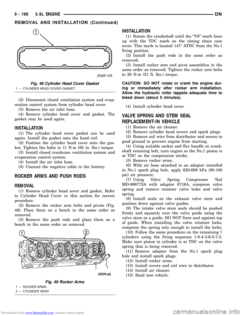
(2) Remove the rocker arm bolts and pivots (Fig.
49). Place them on a bench in the same order as
removed.
(3) Remove the push rods and place them on a
bench in the same order as removed.
INSTALLATION
(1) Rotate the crankshaft until the ªV8º mark lines
up with the TDC mark on the timing chain case
cover. This mark is located 147É ATDC from the No.1
firing position.
(2) Install the push rods in the same order as
removed.
(3) Install rocker arm and pivot assemblies in the
same order as removed. Tighten the rocker arm bolts
to 28 N´m (21 ft. lbs.) torque.
CAUTION: DO NOT rotate or crank the engine dur-
ing or immediately after rocker arm installation.
Allow the hydraulic roller tappets adequate time to
bleed down (about 5 minutes).
(4) Install cylinder head cover.
VALVE SPRING AND STEM SEAL
REPLACEMENT-IN VEHICLE
(1) Remove the air cleaner.
(2) Remove cylinder head covers and spark plugs.
(3) Remove coil wire from distributor and secure to
good ground to prevent engine from starting.
(4) Using suitable socket and flex handle at crank-
shaft retaining bolt, turn engine so the No.1 piston is
at TDC on the compression stroke.
(5) Remove rocker arms.
(6) With air hose attached to an adapter installed
in No.1 spark plug hole, apply 620-689 kPa (90-100
psi) air pressure.
(7) Using Valve Spring Compressor Tool
MD-998772A with adaptor 6716A, compress valve
spring and remove retainer valve locks and valve
spring.
(8) Install seals on the exhaust valve stem and
position down against valve guides.
(9) The intake valve stem seals should be pushed
firmly and squarely over the valve guide using the
valve stem as a guide. DO NOT force seal against top
of guide. When installing the valve retainer locks,
compress the spring only enough to install the locks.
(10) Follow the same procedure on the remaining 7
cylinders using the firing sequence 1-8-4-3-6-5-7-2.
Make sure piston in cylinder is at TDC on the valve
spring that is being removed.
(11) Remove adapter from the No.1 spark plug
hole and install spark plugs.
(12) Install rocker arms.
(13) Install covers and coil wire to distributor.
(14) Install air cleaner.
(15) Road test vehicle.
Fig. 48 Cylinder Head Cover Gasket
1 ± CYLINDER HEAD COVER GASKET
Fig. 49 Rocker Arms
1 ± ROCKER ARMS
2 ± CYLINDER HEAD
9 - 166 5.9L ENGINEDN
REMOVAL AND INSTALLATION (Continued)
Page 169 of 193

Downloaded from www.Manualslib.com manuals search engine (4) Before removing valves, remove any burrs from
valve stem lock grooves to prevent damage to the
valve guides. Identify valves to ensure installation in
original location.
INSTALLATION
(1) Coat valve stems with lubrication oil and insert
them in cylinder head.
(2) If valves or seats are reground, check valve
stem height. If valve is too long, replace cylinder
head.
(3) Install new seals on all valve guides. Install
valve springs and valve retainers.
(4) Compress valve springs with Valve Spring
Compressor Tool MD-998772A, install locks and
release tool. If valves and/or seats are ground, mea-
sure the installed height of springs. Make sure the
measurement is taken from bottom of spring seat in
cylinder head to the bottom surface of spring
retainer. If spacers are installed, measure from the
top of spacer. If height is greater than 42.86 mm
(1-11/16 inches), install a 1.587 mm (1/16 inch)
spacer in head counterbore. This should bring spring
height back to normal 41.27 to 42.86 mm (1-5/8 to
1-11/16 inch).
HYDRAULIC TAPPETS
REMOVAL
(1) Remove the air cleaner assembly and air inlet
hose.
(2) Remove cylinder head cover, rocker assembly
and push rods. Identify push rods to ensure installa-
tion in original location.
(3) Remove intake manifold, yoke retainer and
aligning yokes.
(4) Slide Hydraulic Tappet Remover/Installer Tool
C-4129-A through opening in cylinder head and seat
tool firmly in the head of tappet.
(5) Pull tappet out of bore with a twisting motion.
If all tappets are to be removed, identify tappets to
ensure installation in original location.
INSTALLATION
(1) If the tappet or bore in cylinder block is scored,
scuffed, or shows signs of sticking, ream the bore to
next oversize. Replace with oversize tappet.
(2) Lubricate tappets.
(3) Install tappets and push rods in their original
positions. Ensure that the oil feed hole in the side of
the tappet body faces up (away from the crankshaft).
(4) Install aligning yokes with ARROW toward
camshaft.
(5) Install yoke retainer. Tighten the bolts to 23
N´m (200 in. lbs.) torque. Install intake manifold.
(6) Install push rods in original positions.(7) Install rocker arm.
(8) Install cylinder head cover.
(9) Install air cleaner assembly and air inlet hose.
(10) Start and operate engine. Warm up to normal
operating temperature.
CAUTION: To prevent damage to valve mechanism,
engine must not be run above fast idle until all
hydraulic tappets have filled with oil and have
become quiet.
VIBRATION DAMPER
REMOVAL
(1) Disconnect the battery negative cable.
(2) Remove the cooling system fan.
(3) Remove the cooling fan shroud.
(4) Remove the accessory drive belt. Refer to
COOLING SYSTEM.
(5) Remove vibration damper bolt and washer from
end of crankshaft.
(6) Position Special Tool 8513 Insert into the
crankshaft nose.
(7) Install Special Tool 1026 Three Jaw Puller onto
the vibration damper (Fig. 51).
(8) Pull vibration damper off of the crankshaft.
INSTALLATION
CAUTION: Thoroughly remove any contaminants
from the crankshaft nose and the vibration damper
bore. Failure to do so can cause sever damage to
the crankshaft.
(1) Position the vibration damper onto the crank-
shaft.
Fig. 51 Vibration Damper Removal
1 ± SPECIAL TOOL 8513 INSERT
2 ± SPECIAL TOOL 1026
9 - 168 5.9L ENGINEDN
REMOVAL AND INSTALLATION (Continued)
Page 189 of 193

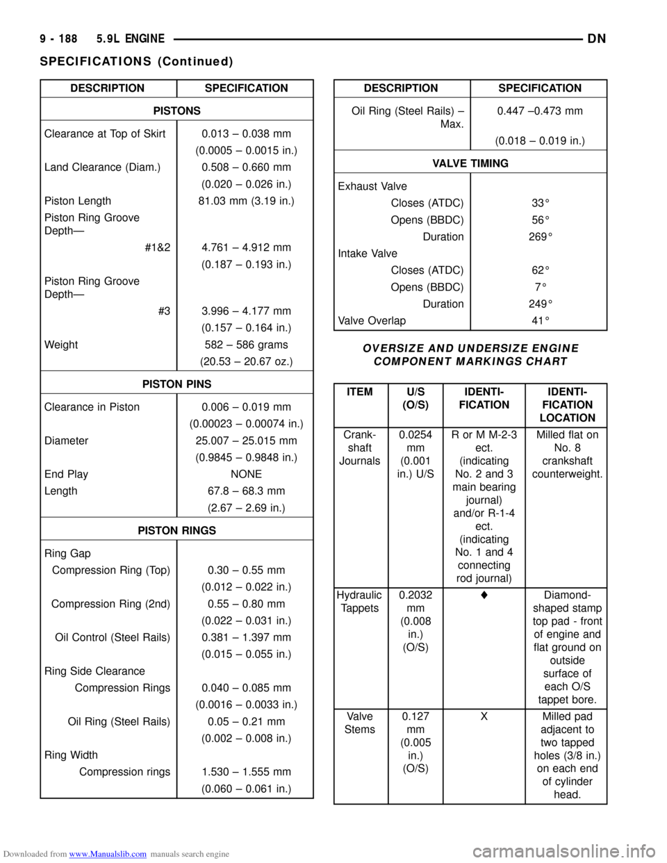
Downloaded from www.Manualslib.com manuals search engine DESCRIPTION SPECIFICATION
PISTONS
Clearance at Top of Skirt 0.013 ± 0.038 mm
(0.0005 ± 0.0015 in.)
Land Clearance (Diam.) 0.508 ± 0.660 mm
(0.020 ± 0.026 in.)
Piston Length 81.03 mm (3.19 in.)
Piston Ring Groove
DepthÐ
#1&2 4.761 ± 4.912 mm
(0.187 ± 0.193 in.)
Piston Ring Groove
DepthÐ
#3 3.996 ± 4.177 mm
(0.157 ± 0.164 in.)
Weight 582 ± 586 grams
(20.53 ± 20.67 oz.)
PISTON PINS
Clearance in Piston 0.006 ± 0.019 mm
(0.00023 ± 0.00074 in.)
Diameter 25.007 ± 25.015 mm
(0.9845 ± 0.9848 in.)
End Play NONE
Length 67.8 ± 68.3 mm
(2.67 ± 2.69 in.)
PISTON RINGS
Ring Gap
Compression Ring (Top) 0.30 ± 0.55 mm
(0.012 ± 0.022 in.)
Compression Ring (2nd) 0.55 ± 0.80 mm
(0.022 ± 0.031 in.)
Oil Control (Steel Rails) 0.381 ± 1.397 mm
(0.015 ± 0.055 in.)
Ring Side Clearance
Compression Rings 0.040 ± 0.085 mm
(0.0016 ± 0.0033 in.)
Oil Ring (Steel Rails) 0.05 ± 0.21 mm
(0.002 ± 0.008 in.)
Ring Width
Compression rings 1.530 ± 1.555 mm
(0.060 ± 0.061 in.)DESCRIPTION SPECIFICATION
Oil Ring (Steel Rails) ±
Max.0.447 ±0.473 mm
(0.018 ± 0.019 in.)
VALVE TIMING
Exhaust Valve
Closes (ATDC) 33É
Opens (BBDC) 56É
Duration 269É
Intake Valve
Closes (ATDC) 62É
Opens (BBDC) 7É
Duration 249É
Valve Overlap 41É
OVERSIZE AND UNDERSIZE ENGINE
COMPONENT MARKINGS CHART
ITEM U/S
(O/S)IDENTI-
FICATIONIDENTI-
FICATION
LOCATION
Crank-
shaft
Journals0.0254
mm
(0.001
in.) U/SR or M M-2-3
ect.
(indicating
No. 2 and 3
main bearing
journal)
and/or R-1-4
ect.
(indicating
No. 1 and 4
connecting
rod journal)Milled flat on
No. 8
crankshaft
counterweight.
Hydraulic
Tappets0.2032
mm
(0.008
in.)
(O/S)lDiamond-
shaped stamp
top pad - front
of engine and
flat ground on
outside
surface of
each O/S
tappet bore.
Valve
Stems0.127
mm
(0.005
in.)
(O/S)X Milled pad
adjacent to
two tapped
holes (3/8 in.)
on each end
of cylinder
head.
9 - 188 5.9L ENGINEDN
SPECIFICATIONS (Continued)