radiator DODGE DURANGO 1998 1.G User Guide
[x] Cancel search | Manufacturer: DODGE, Model Year: 1998, Model line: DURANGO, Model: DODGE DURANGO 1998 1.GPages: 193, PDF Size: 5.65 MB
Page 102 of 193
Downloaded from www.Manualslib.com manuals search engine ENGINE MOUNTÐREAR
REMOVAL
(1) Disconnect the negative cable from the battery.
(2) Raise the vehicle on a hoist.
(3) Support the transmission with a transmission
jack.
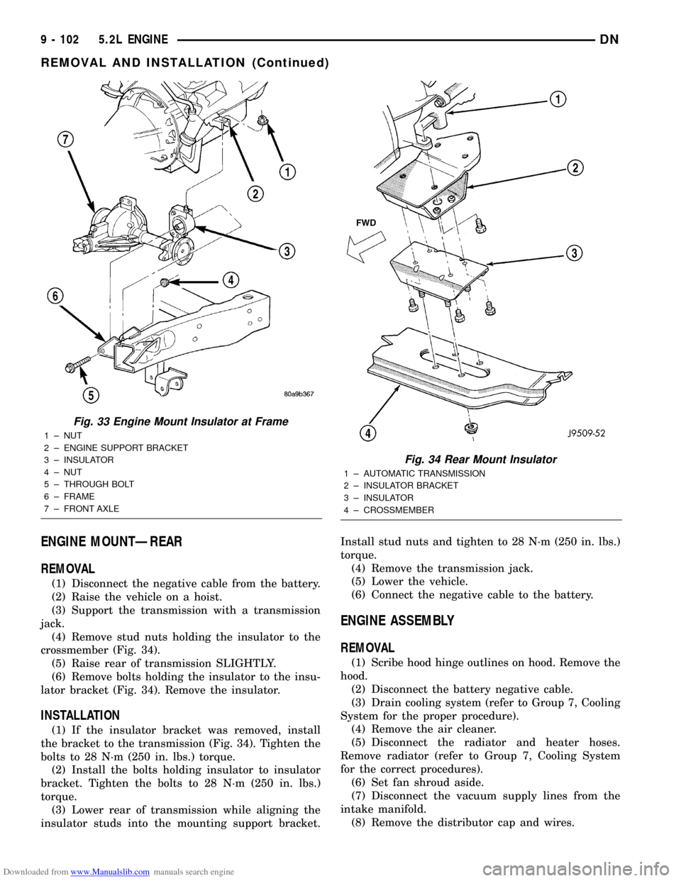
(4) Remove stud nuts holding the insulator to the
crossmember (Fig. 34).
(5) Raise rear of transmission SLIGHTLY.
(6) Remove bolts holding the insulator to the insu-
lator bracket (Fig. 34). Remove the insulator.
INSTALLATION
(1) If the insulator bracket was removed, install
the bracket to the transmission (Fig. 34). Tighten the
bolts to 28 N´m (250 in. lbs.) torque.
(2) Install the bolts holding insulator to insulator
bracket. Tighten the bolts to 28 N´m (250 in. lbs.)
torque.
(3) Lower rear of transmission while aligning the
insulator studs into the mounting support bracket.Install stud nuts and tighten to 28 N´m (250 in. lbs.)
torque.
(4) Remove the transmission jack.
(5) Lower the vehicle.
(6) Connect the negative cable to the battery.
ENGINE ASSEMBLY
REMOVAL
(1) Scribe hood hinge outlines on hood. Remove the
hood.
(2) Disconnect the battery negative cable.
(3) Drain cooling system (refer to Group 7, Cooling
System for the proper procedure).
(4) Remove the air cleaner.
(5) Disconnect the radiator and heater hoses.
Remove radiator (refer to Group 7, Cooling System
for the correct procedures).
(6) Set fan shroud aside.
(7) Disconnect the vacuum supply lines from the
intake manifold.
(8) Remove the distributor cap and wires.
Fig. 33 Engine Mount Insulator at Frame
1 ± NUT
2 ± ENGINE SUPPORT BRACKET
3 ± INSULATOR
4 ± NUT
5 ± THROUGH BOLT
6 ± FRAME
7 ± FRONT AXLE
Fig. 34 Rear Mount Insulator
1 ± AUTOMATIC TRANSMISSION
2 ± INSULATOR BRACKET
3 ± INSULATOR
4 ± CROSSMEMBER
9 - 102 5.2L ENGINEDN
REMOVAL AND INSTALLATION (Continued)
Page 103 of 193
Downloaded from www.Manualslib.com manuals search engine (9) Disconnect the accelerator linkage.
(10) Remove throttle body.
(11) Perform the Fuel System Pressure release
procedure (refer to Group 14, fuel System).
(12) Disconnect the fuel supply line.
(13) Disconnect the starter wires.
(14) Disconnect the oil pressure sending unit wire.
(15) Discharge the air conditioning system, if
equipped (refer to Group 24, Heating and Air Condi-
tioning for service procedures).
(16) Disconnect the air conditioning hoses.
(17) Disconnect the power steering hoses, if
equipped.
(18) Remove starter motor (refer to Group 8B, Bat-
tery/Starter/Generator Service).
(19) Remove the generator (refer to Group 8B, Bat-
tery/Starter/Generator Service).
(20) Raise and support the vehicle on a hoist.
(21) Disconnect exhaust pipe at manifold.
(22) Refer to Group 21, Transmissions for trans-
mission removal.
CAUTION: DO NOT lift the engine by the intake
manifold.
(23) Install an engine lifting fixture.
(24) The engine and front driving axle (engine/ax-
le/transmission) are connected through insulators
and support brackets. Separate the engine as follows:
²LEFT SIDEÐRemove 2 bolts attaching
(engine/pinion nose/transmission) bracket to trans-
mission bell housing. Remove 2 bracket to pinion
nose adaptor bolts. Separate engine from insulator by
removing upper nut washer assembly and bolt from
engine support bracket.
²RIGHT SIDEÐRemove 2 bracket to axle (dis-
connect housing) bolts and a bracket to bell housing
bolt. Separate engine from insulator by removing
upper nut washer assembly and bolt from engine
support bracket.
(25) Lower the vehicle.
(26) Install engine assembly on engine repair
stand.
INSTALLATION
(1) Remove engine from the repair stand and posi-
tion in the engine compartment.
(2) Install an engine support fixture.
(3) Raise and support the vehicle on a hoist.
(4) Install the engine front mounts.
(5) Refer to Group, 21 Transmissions for transmis-
sion installation
(6) Install the inspection plate.
(7) Remove transmission support.
(8) Install exhaust pipe to manifold.
(9) Lower the vehicle.
(10) Remove engine lifting fixture.(11) Install the generator (refer to Group 8B, Bat-
tery/Starter/Generator Service).
(12) Install starter motor (refer to Group 8B, Bat-
tery/Starter/Generator Service).
(13) Connect power steering hoses, if equipped.
(14) Connect air conditioning hoses.
(15) Evacuate and charge the air conditioning sys-
tem, if equipped (refer to Group 24, Heater and Air
Conditioning for service procedures).
(16) Using a new gasket, install throttle body.
Tighten the throttle body bolts to 23 N´m (200 in.
lbs.) torque.
(17) Connect the accelerator linkage.
(18) Connect the starter wires.
(19) Connect the oil pressure sending unit wire.
(20) Install the distributor cap and wiring.
(21) Connect the vacuum supply lines to the
intake manifold.
(22) Connect the fuel supply lines.
(23) Install the radiator (refer to Group 7, Cooling
System). Connect the radiator hoses and heater
hoses.
(24) Install fan shroud in position.
(25) Fill cooling system (refer to Group 7, Cooling
System for the proper procedure).
(26) Install the air cleaner.
(27) Install the battery.
(28) Warm engine and adjust.
(29) Install hood and line up with the scribe
marks.
(30) Road test vehicle.
INTAKE MANIFOLD
REMOVAL
(1) Disconnect the battery negative cable.
(2) Drain the cooling system. Refer to COOLING
SYSTEM.
(3) Remove the A/C compressor. Refer to HEAT-
ING and AIR CONDITIONING.
(4) Remove the generator. Refer to CHARGING
SYSTEM.
(5) Remove the accessory drive bracket.
(6) Remove the air cleaner assembly and air inlet
hose.
(7) Perform the fuel pressure release procedure.
Refer to FUEL SYSTEM.
(8) Disconnect the fuel supply line from the fuel
rail. Refer to FUEL SYSTEM.
(9) Disconnect the accelerator linkage and, if so
equipped, the speed control and transmission kick-
down cables.
(10) Remove the distributor cap and wires.
(11) Disconnect the coil wires.
(12) Disconnect the coolant temperature sending
unit wire.
DN5.2L ENGINE 9 - 103
REMOVAL AND INSTALLATION (Continued)
Page 111 of 193
Downloaded from www.Manualslib.com manuals search engine (9) Tighten chain case cover bolts to 41 N´m (30 ft.
lbs.) torque. Tighten oil pan bolts to 24 N´m (215 in.
lbs.) torque.
(10) Remove the vibration damper bolt and seal
installation tool.
(11) Install vibration damper.
(12) Install water pump and housing assembly
using new gaskets (refer to Group 7, Cooling Sys-
tem). Tighten bolts to 41 N´m (30 ft. lbs.) torque.
(13) Install power steering pump (refer to Group
19, Steering).
(14) Install the serpentine belt (refer to Group 7,
Cooling System).
(15) Install the cooling system fan. Tighten the
bolts to 23 N´m (17 ft. lbs.) torque.
(16) Position the fan shroud and install the bolts.
Tighten the bolts to 11 N´m (95 in. lbs.) torque.
(17) Fill cooling system (refer to Group 7, Cooling
System for the proper procedure).
(18) Connect the negative cable to the battery.
TIMING CHAIN
REMOVAL
(1) Disconnect battery negative cable.
(2) Remove Timing Chain Cover. Refer to Timing
Chain Cover in this section for correct procedure.
(3) Re-install the vibration damper bolt finger
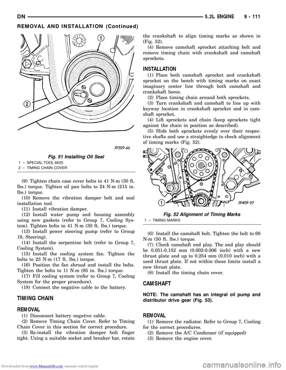
tight. Using a suitable socket and breaker bar, rotatethe crankshaft to align timing marks as shown in
(Fig. 52).
(4) Remove camshaft sprocket attaching bolt and
remove timing chain with crankshaft and camshaft
sprockets.
INSTALLATION
(1) Place both camshaft sprocket and crankshaft
sprocket on the bench with timing marks on exact
imaginary center line through both camshaft and
crankshaft bores.
(2) Place timing chain around both sprockets.
(3) Turn crankshaft and camshaft to line up with
keyway location in crankshaft sprocket and in cam-
shaft sprocket.
(4) Lift sprockets and chain (keep sprockets tight
against the chain in position as described).
(5) Slide both sprockets evenly over their respec-
tive shafts and use a straightedge to check alignment
of timing marks (Fig. 52).
(6) Install the camshaft bolt. Tighten the bolt to 68
N´m (50 ft. lbs.) torque.
(7) Check camshaft end play. The end play should
be 0.051-0.152 mm (0.002-0.006 inch) with a new
thrust plate and up to 0.254 mm (0.010 inch) with a
used thrust plate. If not within these limits install a
new thrust plate.
(8) Install the timing chain cover.
CAMSHAFT
NOTE: The camshaft has an integral oil pump and
distributor drive gear (Fig. 53).
REMOVAL
(1) Remove the radiator. Refer to Group 7, Cooling
for the correct procedures.
(2) Remove the A/C Condenser (if equipped)
(3) Remove the engine cover.
Fig. 51 Installing Oil Seal
1 ± SPECIAL TOOL 6635
2 ± TIMING CHAIN COVER
Fig. 52 Alignment of Timing Marks
1 ± TIMING MARKS
DN5.2L ENGINE 9 - 111
REMOVAL AND INSTALLATION (Continued)
Page 113 of 193
Downloaded from www.Manualslib.com manuals search engine (13) Install distributor and distributor drive shaft.
(14) Install push rods and tappets.
(15) Install rocker arms.
(16) Install timing case cover.
(17) Install cylinder head covers.
(18) Install intake manifold.
(19) Install the engine cover.
(20) Install the A/C Condenser (if equipped).
(21) Install the radiator. Refer to Group 7, Cooling
for the correct procedures.
(22) Refill cooling system. Refer to Group 7, Cool-
ing for the correct procedures.
(23) Start engine check for leaks.
CAMSHAFT BEARINGS
REMOVAL
NOTE: This procedure requires that the engine is
removed from the vehicle.
(1) With engine completely disassembled, drive out
rear cam bearing core plug.
(2) Install proper size adapters and horseshoe
washers (part of Camshaft Bearing Remover/Installer
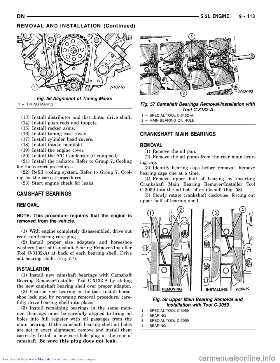
Tool C-3132-A) at back of each bearing shell. Drive
out bearing shells (Fig. 57).
INSTALLATION
(1) Install new camshaft bearings with Camshaft
Bearing Remover/Installer Tool C-3132-A by sliding
the new camshaft bearing shell over proper adapter.
(2) Position rear bearing in the tool. Install horse-
shoe lock and by reversing removal procedure, care-
fully drive bearing shell into place.
(3) Install remaining bearings in the same man-
ner. Bearings must be carefully aligned to bring oil
holes into full register with oil passages from the
main bearing. If the camshaft bearing shell oil holes
are not in exact alignment, remove and install them
correctly. Install a new core hole plug at the rear of
camshaft.Be sure this plug does not leak.
CRANKSHAFT MAIN BEARINGS
REMOVAL
(1) Remove the oil pan.
(2) Remove the oil pump from the rear main bear-
ing cap.
(3) Identify bearing caps before removal. Remove
bearing caps one at a time.
(4) Remove upper half of bearing by inserting
Crankshaft Main Bearing Remover/Installer Tool
C-3059 into the oil hole of crankshaft (Fig. 58).
(5) Slowly rotate crankshaft clockwise, forcing out
upper half of bearing shell.
Fig. 56 Alignment of Timing Marks
1 ± TIMING MARKSFig. 57 Camshaft Bearings Removal/Installation with
Tool C-3132-A
1 ± SPECIAL TOOL C-3132±A
2 ± MAIN BEARING OIL HOLE
Fig. 58 Upper Main Bearing Removal and
Installation with Tool C-3059
1 ± SPECIAL TOOL C-3059
2 ± BEARING
3 ± SPECIAL TOOL C-3059
4 ± BEARING
DN5.2L ENGINE 9 - 113
REMOVAL AND INSTALLATION (Continued)
Page 147 of 193
Downloaded from www.Manualslib.com manuals search engine Ensure the battery is completely charged and the
engine starter motor is in good operating condition.
Otherwise, the indicated compression pressures may
not be valid for diagnosis purposes.
(1) Clean the spark plug recesses with compressed
air.
(2) Remove the spark plugs.
(3) Secure the throttle in the wide-open position.
(4) Disconnect the ignition coil.
(5) Insert a compression pressure gauge and rotate
the engine with the engine starter motor for three
revolutions.
(6) Record the compression pressure on the third
revolution. Continue the test for the remaining cylin-
ders.
Refer to Engine Specifications for the correct
engine compression pressures.
CYLINDER HEAD GASKET FAILURE DIAGNOSIS
A cylinder head gasket leak can be located between
adjacent cylinders or between a cylinder and the
adjacent water jacket.
²Possible indications of the cylinder head gasket
leaking between adjacent cylinders are:
²Loss of engine power
²Engine misfiring
²Poor fuel economy
²Possible indications of the cylinder head gasket
leaking between a cylinder and an adjacent water
jacket are:
²Engine overheating
²Loss of coolant
²Excessive steam (white smoke) emitting from
exhaust
²Coolant foaming
CYLINDER-TO-CYLINDER LEAKAGE TEST
To determine if an engine cylinder head gasket is
leaking between adjacent cylinders, follow the proce-
dures in Cylinder Compression Pressure Test in this
section. An engine cylinder head gasket leaking
between adjacent cylinders will result in approxi-
mately a 50±70% reduction in compression pressure.
CYLINDER-TO-WATER JACKET LEAKAGE TEST
WARNING: USE EXTREME CAUTION WHEN THE
ENGINE IS OPERATING WITH COOLANT PRES-
SURE CAP REMOVED.
VISUAL TEST METHOD
With the engine cool, remove the coolant pressure
cap. Start the engine and allow it to warm up until
thermostat opens.
If a large combustion/compression pressure leak
exists, bubbles will be visible in the coolant.COOLING SYSTEM TESTER METHOD
WARNING: WITH COOLING SYSTEM TESTER IN
PLACE, PRESSURE WILL BUILD UP FAST. EXCES-
SIVE PRESSURE BUILT UP, BY CONTINUOUS
ENGINE OPERATION, MUST BE RELEASED TO A
SAFE PRESSURE POINT. NEVER PERMIT PRES-
SURE TO EXCEED 138 kPa (20 psi).
Install Cooling System Tester 7700 or equivalent to
pressure cap neck. Start the engine and observe the
tester's pressure gauge. If gauge pulsates with every
power stroke of a cylinder a combustion pressure
leak is evident.
CHEMICAL TEST METHOD
Combustion leaks into the cooling system can also
be checked by using Bloc-Chek Kit C-3685-A or
equivalent. Perform test following the procedures
supplied with the tool kit.
CYLINDER COMBUSTION PRESSURE LEAKAGE
TEST
The combustion pressure leakage test provides an
accurate means for determining engine condition.
Combustion pressure leakage testing will detect:
²Exhaust and intake valve leaks (improper seat-
ing)
²Leaks between adjacent cylinders or into water
jacket
²Any causes for combustion/compression pressure
loss
WARNING: DO NOT REMOVE THE RADIATOR CAP
WITH THE SYSTEM HOT AND UNDER PRESSURE.
SERIOUS BURNS FROM HOT COOLANT CAN
OCCUR.
Check the coolant level and fill as required. DO
NOT install the radiator cap.
Start and operate the engine until it attains nor-
mal operating temperature, then turn OFF the
engine.
Remove the spark plugs.
Remove the oil filler cap.
Remove the air cleaner.
Calibrate the tester according to the manufactur-
er's instructions. The shop air source for testing
should maintain 483 kPa (70 psi) minimum, 1,379
kPa (200 psi) maximum and 552 kPa (80 psi) recom-
mended.
Perform the test procedure on each cylinder accord-
ing to the tester manufacturer's instructions. While
testing, listen for pressurized air escaping through
the throttle body, tailpipe or oil filler cap opening.
Check for bubbles in the radiator coolant.
9 - 146 5.9L ENGINEDN
DIAGNOSIS AND TESTING (Continued)
Page 159 of 193
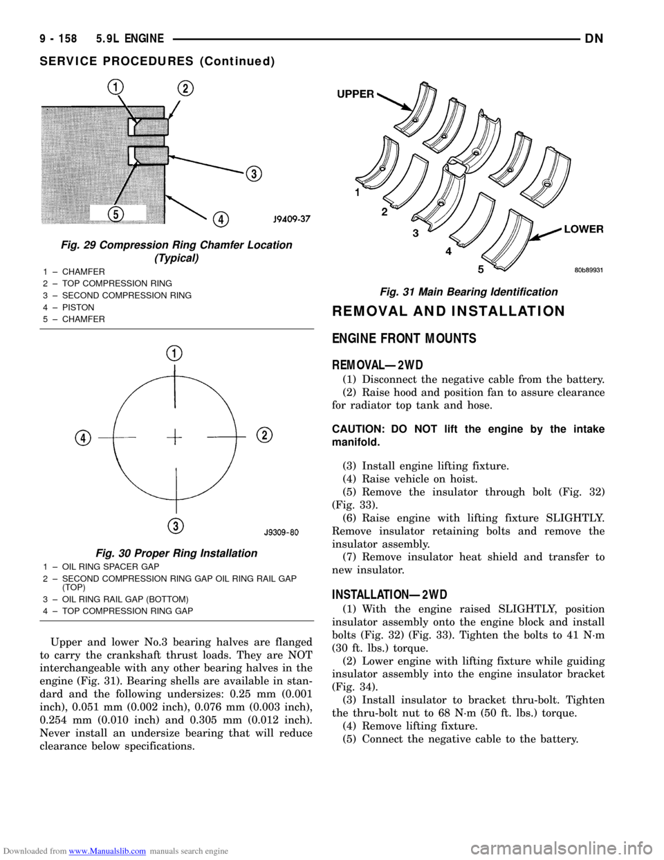
Downloaded from www.Manualslib.com manuals search engine Upper and lower No.3 bearing halves are flanged
to carry the crankshaft thrust loads. They are NOT
interchangeable with any other bearing halves in the
engine (Fig. 31). Bearing shells are available in stan-
dard and the following undersizes: 0.25 mm (0.001
inch), 0.051 mm (0.002 inch), 0.076 mm (0.003 inch),
0.254 mm (0.010 inch) and 0.305 mm (0.012 inch).
Never install an undersize bearing that will reduce
clearance below specifications.
REMOVAL AND INSTALLATION
ENGINE FRONT MOUNTS
REMOVALÐ2WD
(1) Disconnect the negative cable from the battery.
(2) Raise hood and position fan to assure clearance
for radiator top tank and hose.
CAUTION: DO NOT lift the engine by the intake
manifold.
(3) Install engine lifting fixture.
(4) Raise vehicle on hoist.
(5) Remove the insulator through bolt (Fig. 32)
(Fig. 33).
(6) Raise engine with lifting fixture SLIGHTLY.
Remove insulator retaining bolts and remove the
insulator assembly.
(7) Remove insulator heat shield and transfer to
new insulator.
INSTALLATIONÐ2WD
(1) With the engine raised SLIGHTLY, position
insulator assembly onto the engine block and install
bolts (Fig. 32) (Fig. 33). Tighten the bolts to 41 N´m
(30 ft. lbs.) torque.
(2) Lower engine with lifting fixture while guiding
insulator assembly into the engine insulator bracket
(Fig. 34).
(3) Install insulator to bracket thru-bolt. Tighten
the thru-bolt nut to 68 N´m (50 ft. lbs.) torque.
(4) Remove lifting fixture.
(5) Connect the negative cable to the battery.
Fig. 29 Compression Ring Chamfer Location
(Typical)
1 ± CHAMFER
2 ± TOP COMPRESSION RING
3 ± SECOND COMPRESSION RING
4 ± PISTON
5 ± CHAMFER
Fig. 30 Proper Ring Installation
1 ± OIL RING SPACER GAP
2 ± SECOND COMPRESSION RING GAP OIL RING RAIL GAP
(TOP)
3 ± OIL RING RAIL GAP (BOTTOM)
4 ± TOP COMPRESSION RING GAP
Fig. 31 Main Bearing Identification
9 - 158 5.9L ENGINEDN
SERVICE PROCEDURES (Continued)
Page 162 of 193
Downloaded from www.Manualslib.com manuals search engine REMOVALÐ4WD
(1) Disconnect the negative cable from the battery.
(2) Raise the vehicle on a hoist.
(3) Support the transmission with a transmission
jack.
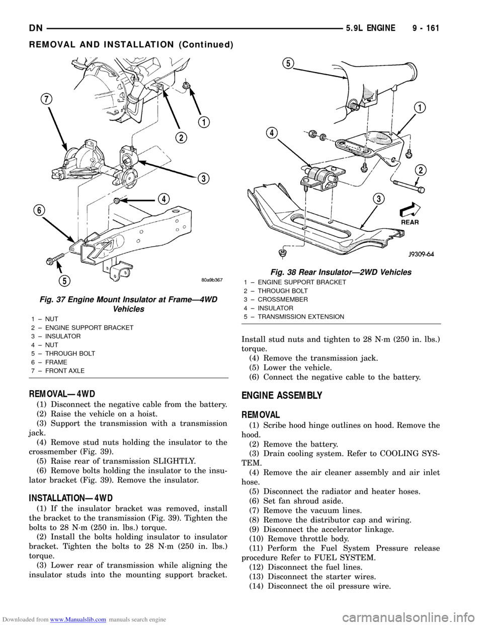
(4) Remove stud nuts holding the insulator to the
crossmember (Fig. 39).
(5) Raise rear of transmission SLIGHTLY.
(6) Remove bolts holding the insulator to the insu-
lator bracket (Fig. 39). Remove the insulator.
INSTALLATIONÐ4WD
(1) If the insulator bracket was removed, install
the bracket to the transmission (Fig. 39). Tighten the
bolts to 28 N´m (250 in. lbs.) torque.
(2) Install the bolts holding insulator to insulator
bracket. Tighten the bolts to 28 N´m (250 in. lbs.)
torque.
(3) Lower rear of transmission while aligning the
insulator studs into the mounting support bracket.Install stud nuts and tighten to 28 N´m (250 in. lbs.)
torque.
(4) Remove the transmission jack.
(5) Lower the vehicle.
(6) Connect the negative cable to the battery.
ENGINE ASSEMBLY
REMOVAL
(1) Scribe hood hinge outlines on hood. Remove the
hood.
(2) Remove the battery.
(3) Drain cooling system. Refer to COOLING SYS-
TEM.
(4) Remove the air cleaner assembly and air inlet
hose.
(5) Disconnect the radiator and heater hoses.
(6) Set fan shroud aside.
(7) Remove the vacuum lines.
(8) Remove the distributor cap and wiring.
(9) Disconnect the accelerator linkage.
(10) Remove throttle body.
(11) Perform the Fuel System Pressure release
procedure Refer to FUEL SYSTEM.
(12) Disconnect the fuel lines.
(13) Disconnect the starter wires.
(14) Disconnect the oil pressure wire.
Fig. 37 Engine Mount Insulator at FrameÐ4WD
Vehicles
1 ± NUT
2 ± ENGINE SUPPORT BRACKET
3 ± INSULATOR
4 ± NUT
5 ± THROUGH BOLT
6 ± FRAME
7 ± FRONT AXLE
Fig. 38 Rear InsulatorÐ2WD Vehicles
1 ± ENGINE SUPPORT BRACKET
2 ± THROUGH BOLT
3 ± CROSSMEMBER
4 ± INSULATOR
5 ± TRANSMISSION EXTENSION
DN5.9L ENGINE 9 - 161
REMOVAL AND INSTALLATION (Continued)
Page 163 of 193
Downloaded from www.Manualslib.com manuals search engine (15) Discharge the air conditioning system, if
equipped. Refer to HEATING and AIR CONDITION-
ING.
(16) Disconnect the air conditioning hoses.
(17) Disconnect the power steering hoses, if
equipped.
(18) Remove starter motor. Refer to STARTING
SYSTEMS.
(19) Remove the generator.
(20) Raise and support the vehicle on a hoist.
(21) Disconnect exhaust pipe at manifold.
(22) Remove Transmission. Refer to TRANSMIS-
SIONS.
CAUTION: DO NOT lift the engine by the intake
manifold.
(23) Install an engine lifting fixture.
(24)2WD VEHICLESÐRemove engine front
mount bolts.
(25)4WD VEHICLESÐThe engine and front
driving axle (engine/axle/transmission) are connectedthrough insulators and support brackets. Separate
the engine as follows:
²LEFT SIDEÐRemove 2 bolts attaching
(engine/pinion nose/transmission) bracket to trans-
mission bell housing. Remove 2 bracket to pinion
nose adaptor bolts. Separate engine from insulator by
removing upper nut washer assembly and bolt from
engine support bracket.
²RIGHT SIDEÐRemove 2 bracket to axle (dis-
connect housing) bolts and a bracket to bell housing
bolt. Separate engine from insulator by removing
upper nut washer assembly and bolt from engine
support bracket.
(26) Lower the vehicle.
(27) Install engine assembly on engine repair
stand.
INSTALLATION
(1) Remove engine from the repair stand and posi-
tion in the engine compartment.
(2) Install an engine support fixture.
(3) Raise and support the vehicle on a hoist.
(4) Install the engine front mounts.
(5) Refer to Group, 21 Transmissions for transmis-
sion installation
(6) Install the inspection plate.
(7) Remove transmission support.
(8) Install exhaust pipe to manifold.
(9) Lower the vehicle.
(10) Remove engine lifting fixture.
(11) Install the generator.
(12) Install starter motor.
(13) Connect power steering hoses, if equipped.
(14) Connect air conditioning hoses.
(15) Evacuate and charge the air conditioning sys-
tem, if equipped.
(16) Using a new gasket, install throttle body.
Tighten the throttle body bolts to 23 N´m (200 in.
lbs.) torque.
(17) Connect the accelerator linkage.
(18) Connect the starter wires.
(19) Connect the oil pressure wire.
(20) Install the distributor cap and wiring.
(21) Connect the vacuum lines.
(22) Connect the fuel lines.
(23) Install the radiator. Connect the radiator
hoses and heater hoses.
(24) Install fan shroud in position.
(25) Fill cooling system.
(26) Install the air cleaner assembly and air inlet
hose.
(27) Install the battery.
(28) Warm engine and adjust.
(29) Install hood and line up with the scribe
marks.
(30) Road test vehicle.
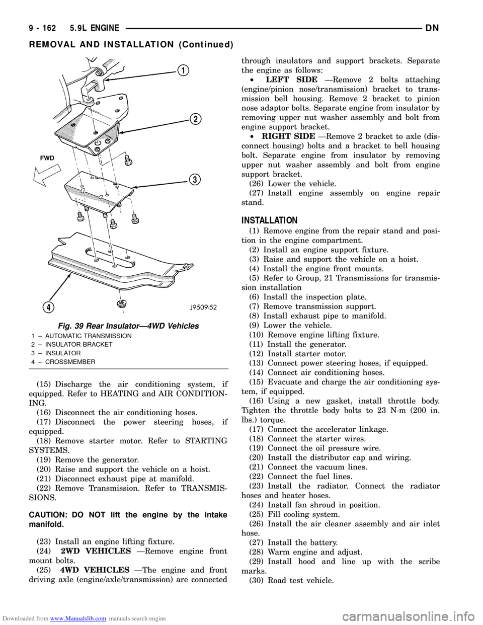
Fig. 39 Rear InsulatorÐ4WD Vehicles
1 ± AUTOMATIC TRANSMISSION
2 ± INSULATOR BRACKET
3 ± INSULATOR
4 ± CROSSMEMBER
9 - 162 5.9L ENGINEDN
REMOVAL AND INSTALLATION (Continued)
Page 172 of 193
Downloaded from www.Manualslib.com manuals search engine REMOVAL
(1) Remove the radiator. Refer to Group 7, Cooling
for the correct procedures.
(2) Remove the A/C Condenser (if equipped).
(3) Remove the engine cover.
(4) Remove intake manifold. Refer to Intake Man-
ifold in this section for the correct procedure.
(5) Remove cylinder head covers.
(6) Remove timing case cover and timing chain.
(7) Remove rocker arms.
(8) Remove push rods and tappets. Identify each
part so it can be installed in its original location.
(9) Remove distributor and lift out the oil pump
and distributor drive shaft.
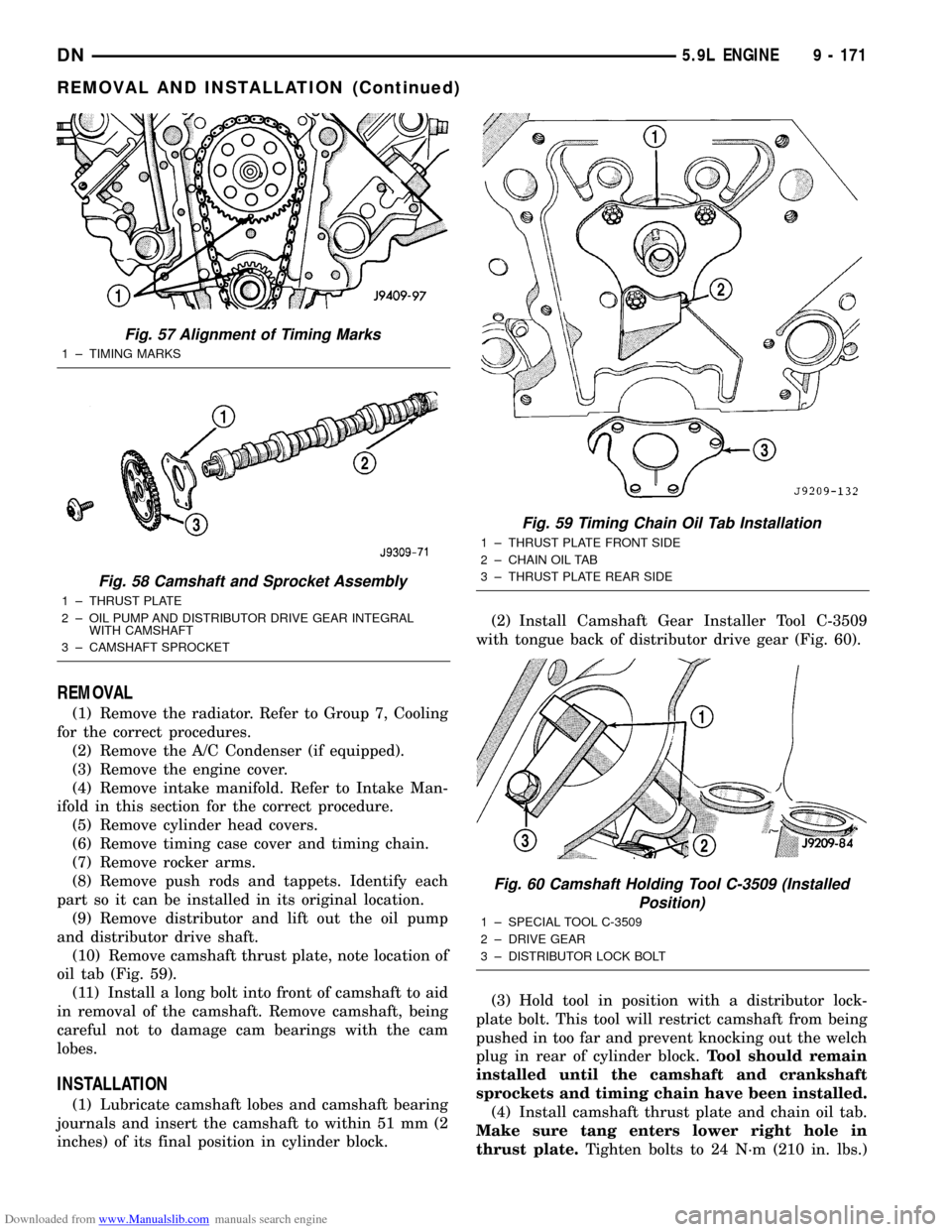
(10) Remove camshaft thrust plate, note location of
oil tab (Fig. 59).
(11) Install a long bolt into front of camshaft to aid
in removal of the camshaft. Remove camshaft, being
careful not to damage cam bearings with the cam
lobes.
INSTALLATION
(1) Lubricate camshaft lobes and camshaft bearing
journals and insert the camshaft to within 51 mm (2
inches) of its final position in cylinder block.(2) Install Camshaft Gear Installer Tool C-3509
with tongue back of distributor drive gear (Fig. 60).
(3) Hold tool in position with a distributor lock-
plate bolt. This tool will restrict camshaft from being
pushed in too far and prevent knocking out the welch
plug in rear of cylinder block.Tool should remain
installed until the camshaft and crankshaft
sprockets and timing chain have been installed.
(4) Install camshaft thrust plate and chain oil tab.
Make sure tang enters lower right hole in
thrust plate.Tighten bolts to 24 N´m (210 in. lbs.)
Fig. 57 Alignment of Timing Marks
1 ± TIMING MARKS
Fig. 58 Camshaft and Sprocket Assembly
1 ± THRUST PLATE
2 ± OIL PUMP AND DISTRIBUTOR DRIVE GEAR INTEGRAL
WITH CAMSHAFT
3 ± CAMSHAFT SPROCKET
Fig. 59 Timing Chain Oil Tab Installation
1 ± THRUST PLATE FRONT SIDE
2 ± CHAIN OIL TAB
3 ± THRUST PLATE REAR SIDE
Fig. 60 Camshaft Holding Tool C-3509 (Installed
Position)
1 ± SPECIAL TOOL C-3509
2 ± DRIVE GEAR
3 ± DISTRIBUTOR LOCK BOLT
DN5.9L ENGINE 9 - 171
REMOVAL AND INSTALLATION (Continued)
Page 173 of 193
Downloaded from www.Manualslib.com manuals search engine torque. Top edge of tab should be flat against thrust
plate in order to catch oil for chain lubrication.
(5) Place both camshaft sprocket and crankshaft
sprocket on the bench with timing marks on exact
imaginary center line through both camshaft and
crankshaft bores.
(6) Place timing chain around both sprockets.
(7) Turn crankshaft and camshaft to line up with
keyway location in crankshaft sprocket and in cam-
shaft sprocket.
(8) Lift sprockets and chain (keep sprockets tight
against the chain in position as described).
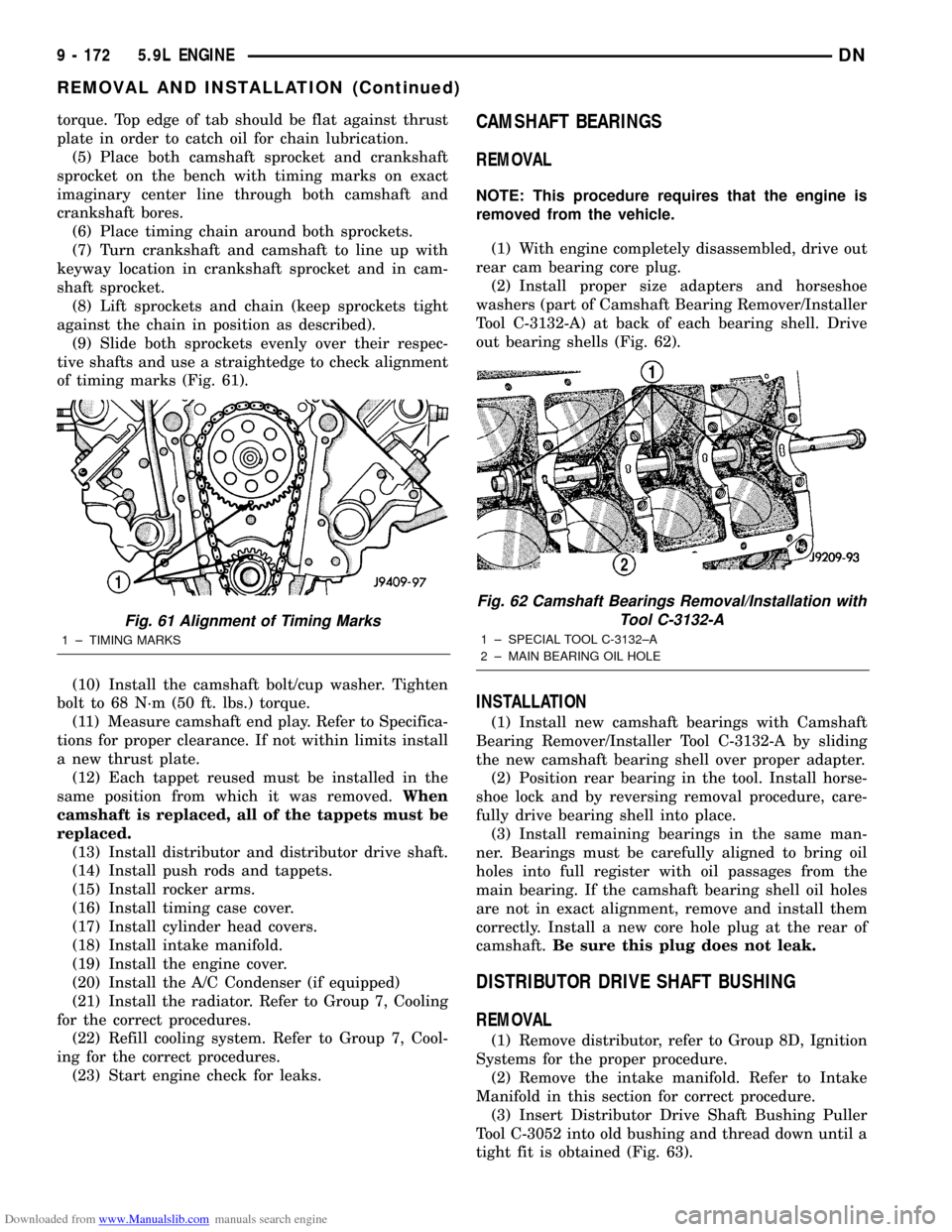
(9) Slide both sprockets evenly over their respec-
tive shafts and use a straightedge to check alignment
of timing marks (Fig. 61).
(10) Install the camshaft bolt/cup washer. Tighten
bolt to 68 N´m (50 ft. lbs.) torque.
(11) Measure camshaft end play. Refer to Specifica-
tions for proper clearance. If not within limits install
a new thrust plate.
(12) Each tappet reused must be installed in the
same position from which it was removed.When
camshaft is replaced, all of the tappets must be
replaced.
(13) Install distributor and distributor drive shaft.
(14) Install push rods and tappets.
(15) Install rocker arms.
(16) Install timing case cover.
(17) Install cylinder head covers.
(18) Install intake manifold.
(19) Install the engine cover.
(20) Install the A/C Condenser (if equipped)
(21) Install the radiator. Refer to Group 7, Cooling
for the correct procedures.
(22) Refill cooling system. Refer to Group 7, Cool-
ing for the correct procedures.
(23) Start engine check for leaks.CAMSHAFT BEARINGS
REMOVAL
NOTE: This procedure requires that the engine is
removed from the vehicle.
(1) With engine completely disassembled, drive out
rear cam bearing core plug.
(2) Install proper size adapters and horseshoe
washers (part of Camshaft Bearing Remover/Installer
Tool C-3132-A) at back of each bearing shell. Drive
out bearing shells (Fig. 62).
INSTALLATION
(1) Install new camshaft bearings with Camshaft
Bearing Remover/Installer Tool C-3132-A by sliding
the new camshaft bearing shell over proper adapter.
(2) Position rear bearing in the tool. Install horse-
shoe lock and by reversing removal procedure, care-
fully drive bearing shell into place.
(3) Install remaining bearings in the same man-
ner. Bearings must be carefully aligned to bring oil
holes into full register with oil passages from the
main bearing. If the camshaft bearing shell oil holes
are not in exact alignment, remove and install them
correctly. Install a new core hole plug at the rear of
camshaft.Be sure this plug does not leak.
DISTRIBUTOR DRIVE SHAFT BUSHING
REMOVAL
(1) Remove distributor, refer to Group 8D, Ignition
Systems for the proper procedure.
(2) Remove the intake manifold. Refer to Intake
Manifold in this section for correct procedure.
(3) Insert Distributor Drive Shaft Bushing Puller
Tool C-3052 into old bushing and thread down until a
tight fit is obtained (Fig. 63).
Fig. 61 Alignment of Timing Marks
1 ± TIMING MARKS
Fig. 62 Camshaft Bearings Removal/Installation with
Tool C-3132-A
1 ± SPECIAL TOOL C-3132±A
2 ± MAIN BEARING OIL HOLE
9 - 172 5.9L ENGINEDN
REMOVAL AND INSTALLATION (Continued)