tow DODGE DURANGO 1998 1.G Owner's Manual
[x] Cancel search | Manufacturer: DODGE, Model Year: 1998, Model line: DURANGO, Model: DODGE DURANGO 1998 1.GPages: 193, PDF Size: 5.65 MB
Page 153 of 193
Downloaded from www.Manualslib.com manuals search engine Damaged or worn threads can be repaired. Essen-
tially, this repair consists of:
²Drilling out worn or damaged threads.
²Tapping the hole with a special Heli-Coil Tap, or
equivalent.
²Installing an insert into the tapped hole to bring
the hole back to its original thread size.
CYLINDER BOREÐHONING
Before honing, stuff plenty of clean shop towels
under the bores and over the crankshaft to keep
abrasive materials from entering the crankshaft
area.
(1) Used carefully, the Cylinder Bore Sizing Hone
C-823, equipped with 220 grit stones, is the best tool
for this job. In addition to deglazing, it will reduce
taper and out-of-round, as well as removing light
scuffing, scoring and scratches. Usually, a few strokes
will clean up a bore and maintain the required lim-
its.
CAUTION: DO NOT use rigid type hones to remove
cylinder wall glaze.
(2) Deglazing of the cylinder walls may be done if
the cylinder bore is straight and round. Use a cylin-
der surfacing hone, Honing Tool C-3501, equipped
with 280 grit stones (C-3501-3810). about 20-60
strokes, depending on the bore condition, will be suf-
ficient to provide a satisfactory surface. Using honing
oil C-3501-3880, or a light honing oil, available from
major oil distributors.
CAUTION: DO NOT use engine or transmission oil,
mineral spirits, or kerosene.
(3) Honing should be done by moving the hone up
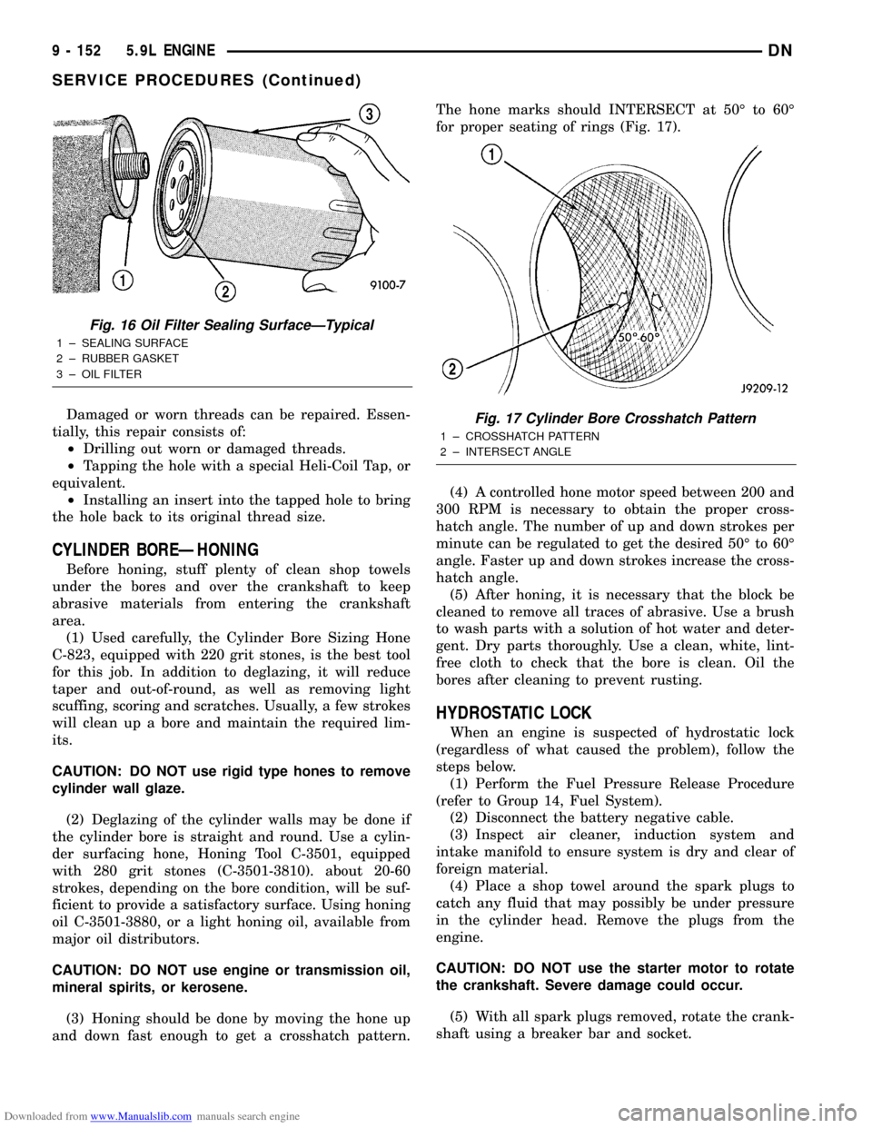
and down fast enough to get a crosshatch pattern.The hone marks should INTERSECT at 50É to 60É
for proper seating of rings (Fig. 17).
(4) A controlled hone motor speed between 200 and
300 RPM is necessary to obtain the proper cross-
hatch angle. The number of up and down strokes per
minute can be regulated to get the desired 50É to 60É
angle. Faster up and down strokes increase the cross-
hatch angle.
(5) After honing, it is necessary that the block be
cleaned to remove all traces of abrasive. Use a brush
to wash parts with a solution of hot water and deter-
gent. Dry parts thoroughly. Use a clean, white, lint-
free cloth to check that the bore is clean. Oil the
bores after cleaning to prevent rusting.
HYDROSTATIC LOCK
When an engine is suspected of hydrostatic lock
(regardless of what caused the problem), follow the
steps below.
(1) Perform the Fuel Pressure Release Procedure
(refer to Group 14, Fuel System).
(2) Disconnect the battery negative cable.
(3) Inspect air cleaner, induction system and
intake manifold to ensure system is dry and clear of
foreign material.
(4) Place a shop towel around the spark plugs to
catch any fluid that may possibly be under pressure
in the cylinder head. Remove the plugs from the
engine.
CAUTION: DO NOT use the starter motor to rotate
the crankshaft. Severe damage could occur.
(5) With all spark plugs removed, rotate the crank-
shaft using a breaker bar and socket.
Fig. 16 Oil Filter Sealing SurfaceÐTypical
1 ± SEALING SURFACE
2 ± RUBBER GASKET
3 ± OIL FILTER
Fig. 17 Cylinder Bore Crosshatch Pattern
1 ± CROSSHATCH PATTERN
2 ± INTERSECT ANGLE
9 - 152 5.9L ENGINEDN
SERVICE PROCEDURES (Continued)
Page 157 of 193
Downloaded from www.Manualslib.com manuals search engine (7) Place timing chain around both sprockets.
(8) Turn crankshaft and camshaft to line up with
keyway location in crankshaft sprocket and in cam-
shaft sprocket.
(9) Lift sprockets and chain (keep sprockets tight
against the chain in position as described).
(10) Slide both sprockets evenly over their respec-
tive shafts and use a straightedge to check alignment
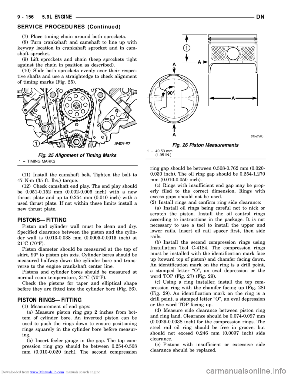
of timing marks (Fig. 25).
(11) Install the camshaft bolt. Tighten the bolt to
47 N´m (35 ft. lbs.) torque.
(12) Check camshaft end play. The end play should
be 0.051-0.152 mm (0.002-0.006 inch) with a new
thrust plate and up to 0.254 mm (0.010 inch) with a
used thrust plate. If not within these limits install a
new thrust plate.
PISTONSÐFITTING
Piston and cylinder wall must be clean and dry.
Specified clearance between the piston and the cylin-
der wall is 0.013-0.038 mm (0.0005-0.0015 inch) at
21ÉC (70ÉF).
Piston diameter should be measured at the top of
skirt, 90É to piston pin axis. Cylinder bores should be
measured halfway down the cylinder bore and trans-
verse to the engine crankshaft center line.
Pistons and cylinder bores should be measured at
normal room temperature, 21ÉC (70ÉF).
Check the pistons for taper and elliptical shape
before they are fitted into the cylinder bore (Fig. 26).
PISTON RINGSÐFITTING
(1) Measurement of end gaps:
(a) Measure piston ring gap 2 inches from bot-
tom of cylinder bore. An inverted piston can be
used to push the rings down to ensure positioning
rings squarely in the cylinder bore before measur-
ing.
(b) Insert feeler gauge in the gap. The top com-
pression ring gap should be between 0.254-0.508
mm (0.010-0.020 inch). The second compressionring gap should be between 0.508-0.762 mm (0.020-
0.030 inch). The oil ring gap should be 0.254-1.270
mm (0.010-0.050 inch).
(c) Rings with insufficient end gap may be prop-
erly filed to the correct dimension. Rings with
excess gaps should not be used.
(2) Install rings and confirm ring side clearance:
(a) Install oil rings being careful not to nick or
scratch the piston. Install the oil control rings
according to instructions in the package. It is not
necessary to use a tool to install the upper and
lower rails. Insert oil rail spacer first, then side
rails.
(b) Install the second compression rings using
Installation Tool C-4184. The compression rings
must be installed with the identification mark face
up (toward top of piston) and chamfer facing down.
An identification mark on the ring is a drill point,
a stamped letter ªOº, an oval depression or the
word TOP (Fig. 27) (Fig. 29).
(c) Using a ring installer, install the top com-
pression ring with the chamfer facing up (Fig. 28)
(Fig. 29). An identification mark on the ring is a
drill point, a stamped letter ªOº, an oval depression
or the word TOP facing up.
(d) Measure side clearance between piston ring
and ring land. Clearance should be 0.074-0.097 mm
(0.0029-0.0038 inch) for the compression rings. The
steel rail oil ring should be free in groove, but
should not exceed 0.246 mm (0.0097 inch) side
clearance.
(e) Pistons with insufficient or excessive side
clearance should be replaced.
Fig. 25 Alignment of Timing Marks
1 ± TIMING MARKS
Fig. 26 Piston Measurements
1 ± 49.53 mm
(1.95 IN.)
9 - 156 5.9L ENGINEDN
SERVICE PROCEDURES (Continued)
Page 169 of 193
Downloaded from www.Manualslib.com manuals search engine (4) Before removing valves, remove any burrs from
valve stem lock grooves to prevent damage to the
valve guides. Identify valves to ensure installation in
original location.
INSTALLATION
(1) Coat valve stems with lubrication oil and insert
them in cylinder head.
(2) If valves or seats are reground, check valve
stem height. If valve is too long, replace cylinder
head.
(3) Install new seals on all valve guides. Install
valve springs and valve retainers.
(4) Compress valve springs with Valve Spring
Compressor Tool MD-998772A, install locks and
release tool. If valves and/or seats are ground, mea-
sure the installed height of springs. Make sure the
measurement is taken from bottom of spring seat in
cylinder head to the bottom surface of spring
retainer. If spacers are installed, measure from the
top of spacer. If height is greater than 42.86 mm
(1-11/16 inches), install a 1.587 mm (1/16 inch)
spacer in head counterbore. This should bring spring
height back to normal 41.27 to 42.86 mm (1-5/8 to
1-11/16 inch).
HYDRAULIC TAPPETS
REMOVAL
(1) Remove the air cleaner assembly and air inlet
hose.
(2) Remove cylinder head cover, rocker assembly
and push rods. Identify push rods to ensure installa-
tion in original location.
(3) Remove intake manifold, yoke retainer and
aligning yokes.
(4) Slide Hydraulic Tappet Remover/Installer Tool
C-4129-A through opening in cylinder head and seat
tool firmly in the head of tappet.
(5) Pull tappet out of bore with a twisting motion.
If all tappets are to be removed, identify tappets to
ensure installation in original location.
INSTALLATION
(1) If the tappet or bore in cylinder block is scored,
scuffed, or shows signs of sticking, ream the bore to
next oversize. Replace with oversize tappet.
(2) Lubricate tappets.
(3) Install tappets and push rods in their original
positions. Ensure that the oil feed hole in the side of
the tappet body faces up (away from the crankshaft).
(4) Install aligning yokes with ARROW toward
camshaft.
(5) Install yoke retainer. Tighten the bolts to 23
N´m (200 in. lbs.) torque. Install intake manifold.
(6) Install push rods in original positions.(7) Install rocker arm.
(8) Install cylinder head cover.
(9) Install air cleaner assembly and air inlet hose.
(10) Start and operate engine. Warm up to normal
operating temperature.
CAUTION: To prevent damage to valve mechanism,
engine must not be run above fast idle until all
hydraulic tappets have filled with oil and have
become quiet.
VIBRATION DAMPER
REMOVAL
(1) Disconnect the battery negative cable.
(2) Remove the cooling system fan.
(3) Remove the cooling fan shroud.
(4) Remove the accessory drive belt. Refer to
COOLING SYSTEM.
(5) Remove vibration damper bolt and washer from
end of crankshaft.
(6) Position Special Tool 8513 Insert into the
crankshaft nose.
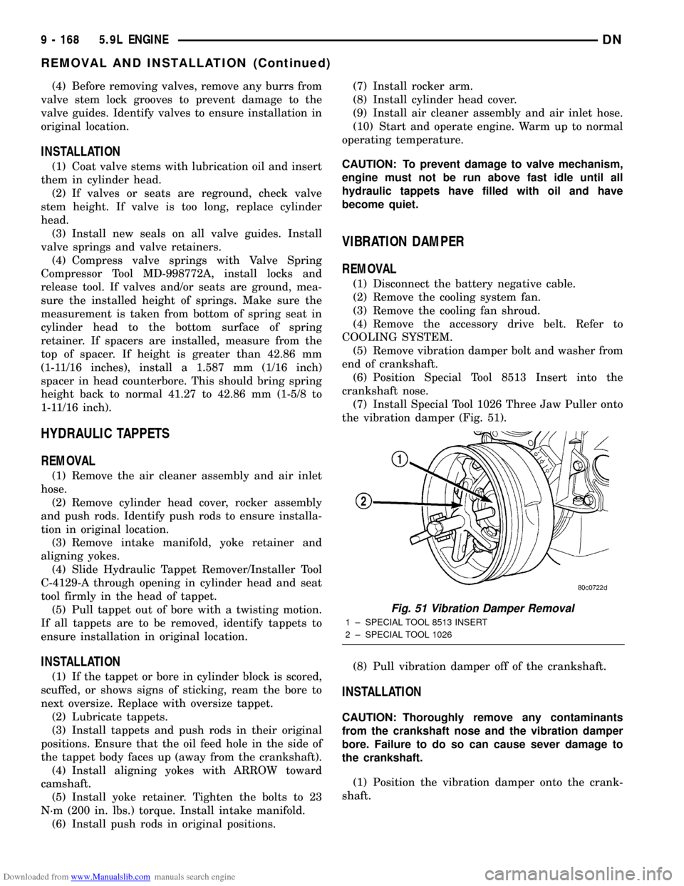
(7) Install Special Tool 1026 Three Jaw Puller onto
the vibration damper (Fig. 51).
(8) Pull vibration damper off of the crankshaft.
INSTALLATION
CAUTION: Thoroughly remove any contaminants
from the crankshaft nose and the vibration damper
bore. Failure to do so can cause sever damage to
the crankshaft.
(1) Position the vibration damper onto the crank-
shaft.
Fig. 51 Vibration Damper Removal
1 ± SPECIAL TOOL 8513 INSERT
2 ± SPECIAL TOOL 1026
9 - 168 5.9L ENGINEDN
REMOVAL AND INSTALLATION (Continued)
Page 174 of 193
Downloaded from www.Manualslib.com manuals search engine (4) Hold puller screw and tighten puller nut until
bushing is removed.
INSTALLATION
(1) Slide new bushing over burnishing end of Dis-
tributor Drive Shaft Bushing Driver/Burnisher Tool
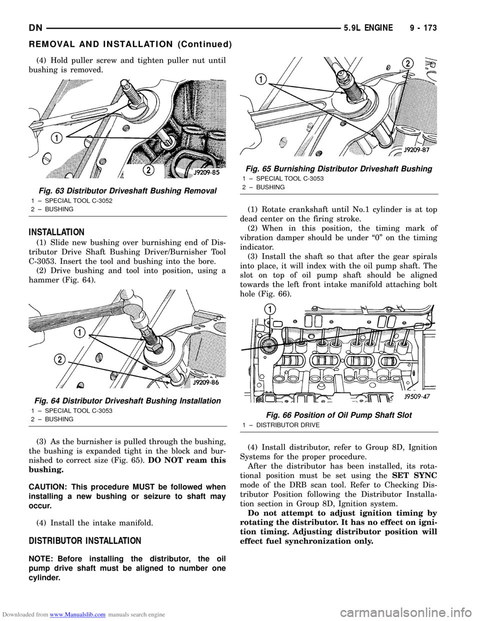
C-3053. Insert the tool and bushing into the bore.
(2) Drive bushing and tool into position, using a
hammer (Fig. 64).
(3) As the burnisher is pulled through the bushing,
the bushing is expanded tight in the block and bur-
nished to correct size (Fig. 65).DO NOT ream this
bushing.
CAUTION: This procedure MUST be followed when
installing a new bushing or seizure to shaft may
occur.
(4) Install the intake manifold.
DISTRIBUTOR INSTALLATION
NOTE: Before installing the distributor, the oil
pump drive shaft must be aligned to number one
cylinder.(1) Rotate crankshaft until No.1 cylinder is at top
dead center on the firing stroke.
(2) When in this position, the timing mark of
vibration damper should be under ª0º on the timing
indicator.
(3) Install the shaft so that after the gear spirals
into place, it will index with the oil pump shaft. The
slot on top of oil pump shaft should be aligned
towards the left front intake manifold attaching bolt
hole (Fig. 66).
(4) Install distributor, refer to Group 8D, Ignition
Systems for the proper procedure.
After the distributor has been installed, its rota-
tional position must be set using theSET SYNC
mode of the DRB scan tool. Refer to Checking Dis-
tributor Position following the Distributor Installa-
tion section in Group 8D, Ignition system.
Do not attempt to adjust ignition timing by
rotating the distributor. It has no effect on igni-
tion timing. Adjusting distributor position will
effect fuel synchronization only.
Fig. 63 Distributor Driveshaft Bushing Removal
1 ± SPECIAL TOOL C-3052
2 ± BUSHING
Fig. 64 Distributor Driveshaft Bushing Installation
1 ± SPECIAL TOOL C-3053
2 ± BUSHING
Fig. 65 Burnishing Distributor Driveshaft Bushing
1 ± SPECIAL TOOL C-3053
2 ± BUSHING
Fig. 66 Position of Oil Pump Shaft Slot
1 ± DISTRIBUTOR DRIVE
DN5.9L ENGINE 9 - 173
REMOVAL AND INSTALLATION (Continued)
Page 177 of 193
Downloaded from www.Manualslib.com manuals search engine INSTALLATION
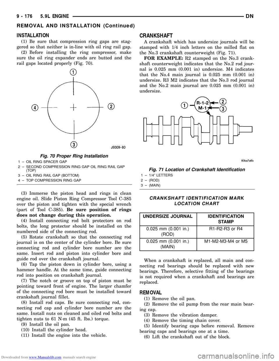
(1) Be sure that compression ring gaps are stag-
gered so that neither is in-line with oil ring rail gap.
(2) Before installing the ring compressor, make
sure the oil ring expander ends are butted and the
rail gaps located properly (Fig. 70).
(3) Immerse the piston head and rings in clean
engine oil. Slide Piston Ring Compressor Tool C-385
over the piston and tighten with the special wrench
(part of Tool C-385).Be sure position of rings
does not change during this operation.
(4) Install connecting rod bolt protectors on rod
bolts, the long protector should be installed on the
numbered side of the connecting rod.
(5) Rotate crankshaft so that the connecting rod
journal is on the center of the cylinder bore. Be sure
connecting rod and cylinder bore number are the
same. Insert rod and piston into cylinder bore and
guide rod over the crankshaft journal.
(6) Tap the piston down in cylinder bore, using a
hammer handle. At the same time, guide connecting
rod into position on crankshaft journal.
(7) The notch or groove on top of piston must be
pointing toward front of engine. The larger chamfer
of the connecting rod bore must be installed toward
crankshaft journal fillet.
(8) Install rod caps. Be sure connecting rod, con-
necting rod cap and cylinder bore number are the
same. Install nuts on cleaned and oiled rod bolts and
tighten nuts to 61 N´m (45 ft. lbs.) torque.
(9) Install the oil pan.
(10) Install the cylinder head.
(11) Install the engine into the vehicle.
CRANKSHAFT
A crankshaft which has undersize journals will be
stamped with 1/4 inch letters on the milled flat on
the No.3 crankshaft counterweight (Fig. 71).
FOR EXAMPLE:R2 stamped on the No.3 crank-
shaft counterweight indicates that the No.2 rod jour-
nal is 0.025 mm (0.001 in) undersize. M4 indicates
that the No.4 main journal is 0.025 mm (0.001 in)
undersize. R3 M2 indicates that the No.3 rod journal
and the No.2 main journal are 0.025 mm (0.001 in)
undersize.
When a crankshaft is replaced, all main and con-
necting rod bearings should be replaced with new
bearings. Therefore, selective fitting of the bearings
is not required when a crankshaft and bearings are
replaced.
REMOVAL
(1) Remove the oil pan.
(2) Remove the oil pump from the rear main bear-
ing cap.
(3) Remove the vibration damper.
(4) Remove the timing chain cover.
(5) Identify bearing caps before removal. Remove
bearing caps and bearings one at a time.
(6) Lift the crankshaft out of the block.
Fig. 70 Proper Ring Installation
1 ± OIL RING SPACER GAP
2 ± SECOND COMPRESSION RING GAP OIL RING RAIL GAP
(TOP)
3 ± OIL RING RAIL GAP (BOTTOM)
4 ± TOP COMPRESSION RING GAP
Fig. 71 Location of Crankshaft Identification
1 ± 1/4º LETTERS
2 ± (ROD)
3 ± (MAIN)
CRANKSHAFT IDENTIFICATION MARK
LOCATION CHART
UNDERSIZE JOURNAL IDENTIFICATION
STAMP
0.025 mm (0.001 in.)
(ROD)R1-R2-R3 or R4
0.025 mm (0.001 in.)
(MAIN)M1-M2-M3-M4 or M5
9 - 176 5.9L ENGINEDN
REMOVAL AND INSTALLATION (Continued)
Page 178 of 193
Downloaded from www.Manualslib.com manuals search engine (7) Remove and discard the crankshaft rear oil
seals.
(8) Remove and discard the front crankshaft oil
seal.
INSPECTION OF JOURNALS
The crankshaft connecting rod and main journals
should be checked for excessive wear, taper and scor-
ing. The maximum taper or out-of-round on any
crankshaft journal is 0.025 mm (0.001 inch).
Journal grinding should not exceed 0.305 mm
(0.012 inch) under the standard journal diameter. DO
NOT grind thrust faces of No.3 main bearing. DO
NOT nick crank pin or bearing fillets. After grinding,
remove rough edges from crankshaft oil holes and
clean out all oil passages.
CAUTION: After any journal grind, it is important
that the final paper or cloth polish be in the same
direction as the engine rotates.
CLEANING
Clean Loctite 518 residue and sealant from the cyl-
inder block and rear cap mating surface. Do this
before applying the Loctite drop and the installation
of rear cap.
INSTALLATION
(1) Lightly oil the new upper seal lips with engine
oil.
(2) Install the new upper rear bearing oil seal with
the white paint facing towards the rear of the engine.
(3) Position the crankshaft into the cylinder block.
(4) Lightly oil the new lower seal lips with engine
oil.
(5) Install the new lower rear bearing oil seal into
the bearing cap with the white paint facing towards
the rear of the engine.
(6) Apply 5 mm (0.20 in) drop of Loctite 518, or
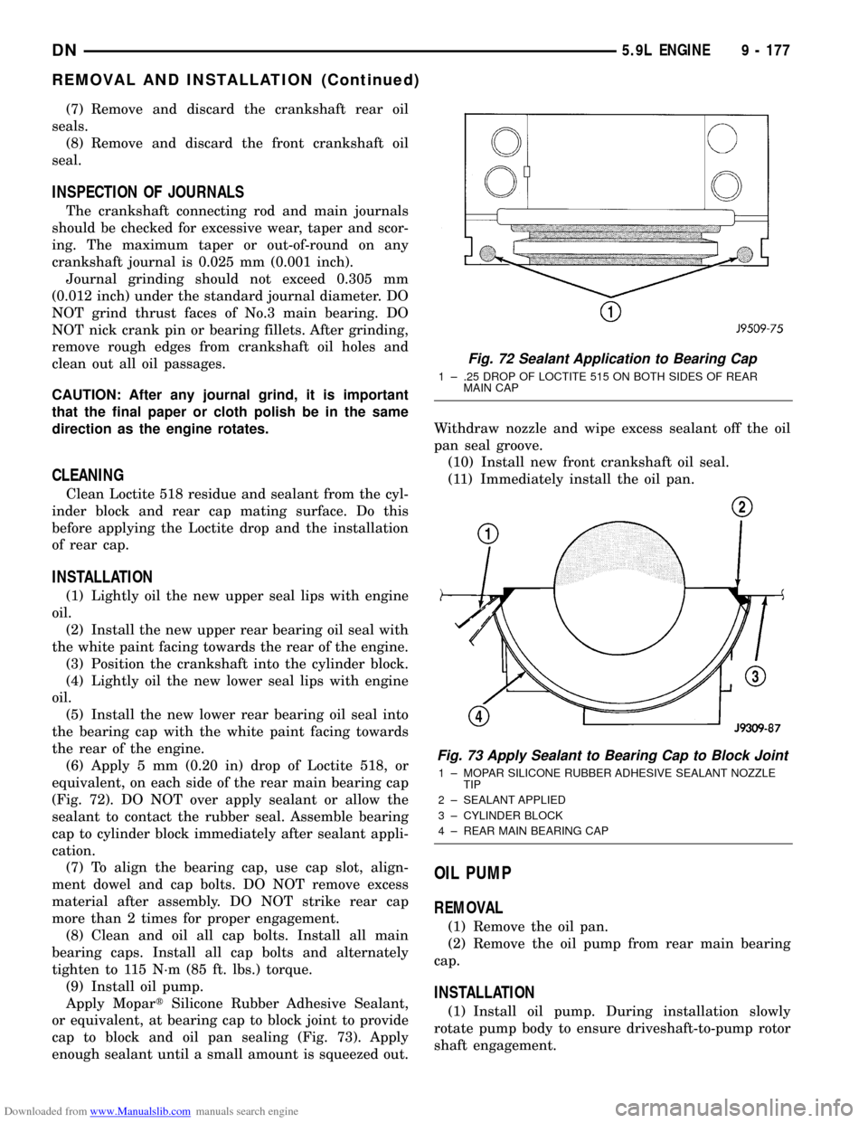
equivalent, on each side of the rear main bearing cap
(Fig. 72). DO NOT over apply sealant or allow the
sealant to contact the rubber seal. Assemble bearing
cap to cylinder block immediately after sealant appli-
cation.
(7) To align the bearing cap, use cap slot, align-
ment dowel and cap bolts. DO NOT remove excess
material after assembly. DO NOT strike rear cap
more than 2 times for proper engagement.
(8) Clean and oil all cap bolts. Install all main
bearing caps. Install all cap bolts and alternately
tighten to 115 N´m (85 ft. lbs.) torque.
(9) Install oil pump.
Apply MopartSilicone Rubber Adhesive Sealant,
or equivalent, at bearing cap to block joint to provide
cap to block and oil pan sealing (Fig. 73). Apply
enough sealant until a small amount is squeezed out.Withdraw nozzle and wipe excess sealant off the oil
pan seal groove.
(10) Install new front crankshaft oil seal.
(11) Immediately install the oil pan.
OIL PUMP
REMOVAL
(1) Remove the oil pan.
(2) Remove the oil pump from rear main bearing
cap.
INSTALLATION
(1) Install oil pump. During installation slowly
rotate pump body to ensure driveshaft-to-pump rotor
shaft engagement.
Fig. 72 Sealant Application to Bearing Cap
1 ± .25 DROP OF LOCTITE 515 ON BOTH SIDES OF REAR
MAIN CAP
Fig. 73 Apply Sealant to Bearing Cap to Block Joint
1 ± MOPAR SILICONE RUBBER ADHESIVE SEALANT NOZZLE
TIP
2 ± SEALANT APPLIED
3 ± CYLINDER BLOCK
4 ± REAR MAIN BEARING CAP
DN5.9L ENGINE 9 - 177
REMOVAL AND INSTALLATION (Continued)
Page 180 of 193
Downloaded from www.Manualslib.com manuals search engine CRANKSHAFT OIL SEALSÐREAR
The service seal is a 2 piece, viton seal. The upper
seal half can be installed with crankshaft removed
from engine or with crankshaft installed. When a
new upper seal is installed, install a new lower seal.
The lower seal half can only be installed with the
rear main bearing cap removed.
UPPER SEAL ÐCRANKSHAFT REMOVED
REMOVAL
(1) Remove the crankshaft. Discard the old upper
seal.
INSTALLATION
(1) Clean the cylinder block rear cap mating sur-
face. Make sure the seal groove is free of debris.
(2) Lightly oil the new upper seal lips with engine
oil.
(3) Install the new upper rear bearing oil seal with
the white paint facing towards the rear of the engine.
(4) Position the crankshaft into the cylinder block.
(5) Lightly oil the new lower seal lips with engine
oil.
(6) Install the new lower rear bearing oil seal into
the bearing cap with the white paint facing towards
the rear of the engine.
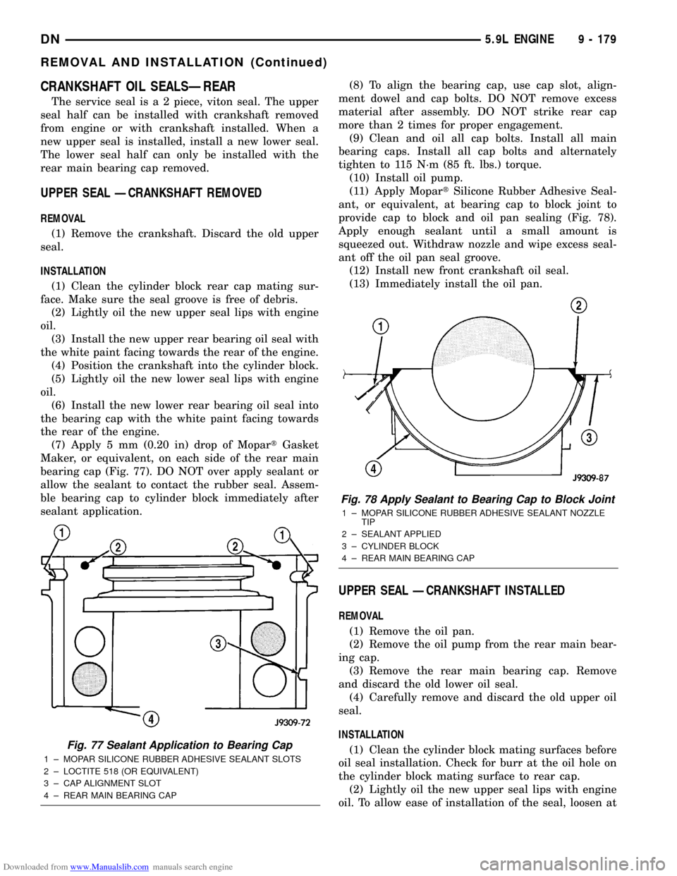
(7) Apply 5 mm (0.20 in) drop of MopartGasket
Maker, or equivalent, on each side of the rear main
bearing cap (Fig. 77). DO NOT over apply sealant or
allow the sealant to contact the rubber seal. Assem-
ble bearing cap to cylinder block immediately after
sealant application.(8) To align the bearing cap, use cap slot, align-
ment dowel and cap bolts. DO NOT remove excess
material after assembly. DO NOT strike rear cap
more than 2 times for proper engagement.
(9) Clean and oil all cap bolts. Install all main
bearing caps. Install all cap bolts and alternately
tighten to 115 N´m (85 ft. lbs.) torque.
(10) Install oil pump.
(11) Apply MopartSilicone Rubber Adhesive Seal-
ant, or equivalent, at bearing cap to block joint to
provide cap to block and oil pan sealing (Fig. 78).
Apply enough sealant until a small amount is
squeezed out. Withdraw nozzle and wipe excess seal-
ant off the oil pan seal groove.
(12) Install new front crankshaft oil seal.
(13) Immediately install the oil pan.
UPPER SEAL ÐCRANKSHAFT INSTALLED
REMOVAL
(1) Remove the oil pan.
(2) Remove the oil pump from the rear main bear-
ing cap.
(3) Remove the rear main bearing cap. Remove
and discard the old lower oil seal.
(4) Carefully remove and discard the old upper oil
seal.
INSTALLATION
(1) Clean the cylinder block mating surfaces before
oil seal installation. Check for burr at the oil hole on
the cylinder block mating surface to rear cap.
(2) Lightly oil the new upper seal lips with engine
oil. To allow ease of installation of the seal, loosen at
Fig. 77 Sealant Application to Bearing Cap
1 ± MOPAR SILICONE RUBBER ADHESIVE SEALANT SLOTS
2 ± LOCTITE 518 (OR EQUIVALENT)
3 ± CAP ALIGNMENT SLOT
4 ± REAR MAIN BEARING CAP
Fig. 78 Apply Sealant to Bearing Cap to Block Joint
1 ± MOPAR SILICONE RUBBER ADHESIVE SEALANT NOZZLE
TIP
2 ± SEALANT APPLIED
3 ± CYLINDER BLOCK
4 ± REAR MAIN BEARING CAP
DN5.9L ENGINE 9 - 179
REMOVAL AND INSTALLATION (Continued)
Page 181 of 193
Downloaded from www.Manualslib.com manuals search engine least the 2 main bearing caps forward of the rear
bearing cap.
(3) Rotate the new upper seal into the cylinder
block being careful not to shave or cut the outer sur-
face of the seal. To assure proper installation, use the
installation tool provided with the kit. Install the
new seal with the white paint facing towards the
rear of the engine.
(4) Install the new lower rear bearing oil seal into
the bearing cap with the white paint facing towards
the rear of the engine.
(5) Apply 5 mm (0.20 in) drop of MopartGasket
Maker, or equivalent, on each side of the rear main
bearing cap (Fig. 77). DO NOT over apply sealant or
allow the sealant to contact the rubber seal. Assem-
ble bearing cap to cylinder block immediately after
sealant application. Be sure the white paint faces
toward the rear of the engine.
(6) To align the bearing cap, use cap slot, align-
ment dowel and cap bolts. DO NOT remove excess
material after assembly. DO NOT strike rear cap
more than 2 times for proper engagement.
(7) Install the rear main bearing cap with cleaned
and oiled cap bolts. Alternately tighten ALL cap bolts
to 115 N´m (85 ft. lbs.) torque.
(8) Install oil pump.
(9) Apply MopartSilicone Rubber Adhesive Seal-
ant, or equivalent, at bearing cap to block joint to
provide cap to block and oil pan sealing (Fig. 78).
Apply enough sealant until a small amount is
squeezed out. Withdraw nozzle and wipe excess seal-
ant off the oil pan seal groove.
(10) Immediately install the oil pan.
LOWER SEAL
REMOVAL
(1) Remove the oil pan.
(2) Remove the oil pump from the rear main bear-
ing cap.
(3) Remove the rear main bearing cap and discard
the old lower seal.
INSTALLATION
(1) Clean the rear main cap mating surfaces
including the oil pan gasket groove.
(2) Carefully install a new upper seal (refer to
Upper Seal Replacement - Crankshaft Installed pro-
cedure above).
(3) Lightly oil the new lower seal lips with engine
oil.
(4) Install a new lower seal in bearing cap with
the white paint facing the rear of engine.
(5) Apply 5 mm (0.20 in) drop of MopartGasket
Maker, or equivalent, on each side of the rear main
bearing cap (Fig. 77). DO NOT over apply sealant orallow the sealant to contact the rubber seal. Assem-
ble bearing cap to cylinder block immediately after
sealant application.
(6) To align the bearing cap, use cap slot, align-
ment dowel and cap bolts. DO NOT remove excess
material after assembly. DO NOT strike rear cap
more than 2 times for proper engagement.
(7) Install the rear main bearing cap with cleaned
and oiled cap bolts. Alternately tighten the cap bolts
to 115 N´m (85 ft. lbs.) torque.
(8) Install oil pump.
(9) Apply MopartSilicone Rubber Adhesive Seal-
ant, or equivalent, at bearing cap to block joint to
provide cap to block and oil pan sealing (Fig. 78).
Apply enough sealant until a small amount is
squeezed out. Withdraw nozzle and wipe excess seal-
ant off the oil pan seal groove.
(10) Immediately install the oil pan.
ENGINE CORE OIL AND CAMSHAFT PLUGS
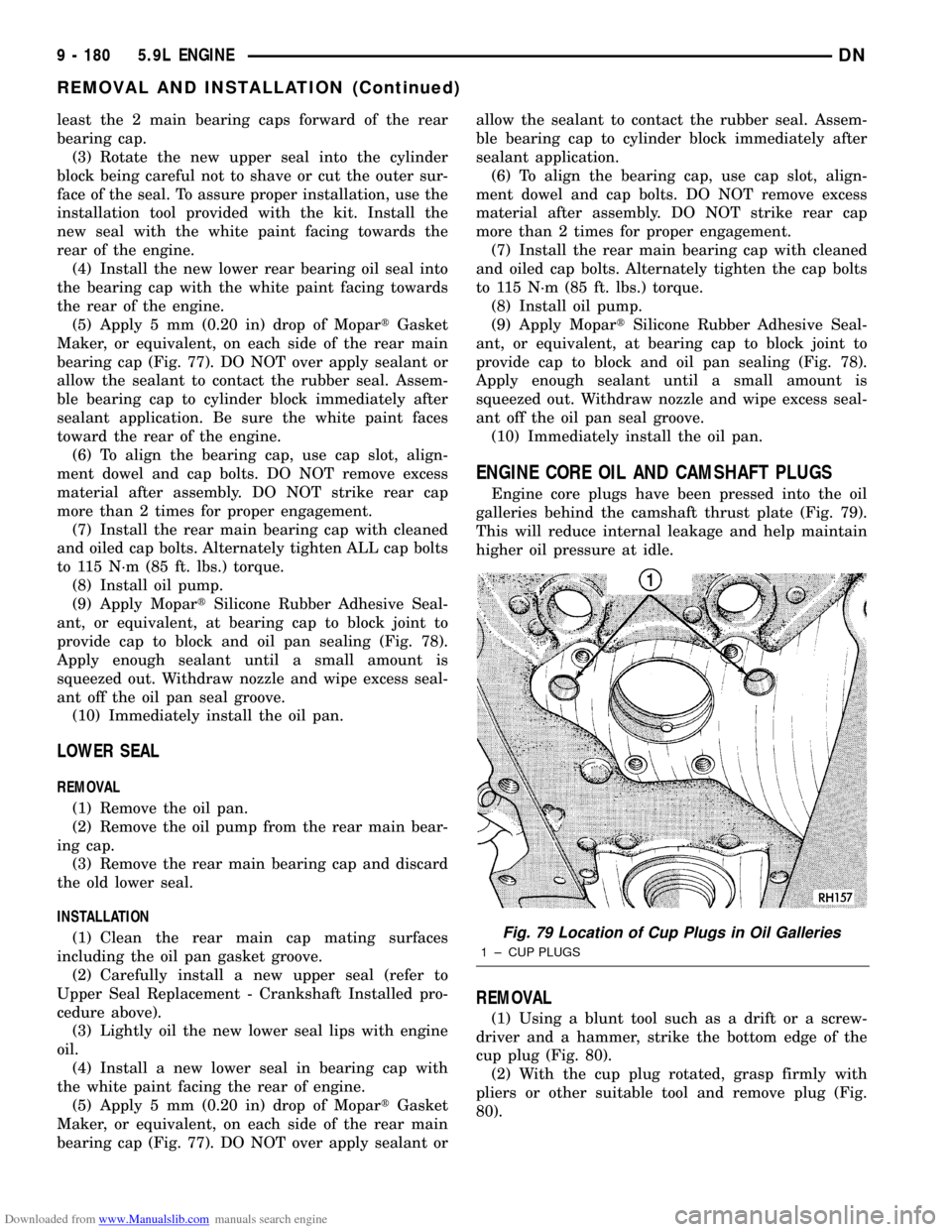
Engine core plugs have been pressed into the oil
galleries behind the camshaft thrust plate (Fig. 79).
This will reduce internal leakage and help maintain
higher oil pressure at idle.
REMOVAL
(1) Using a blunt tool such as a drift or a screw-
driver and a hammer, strike the bottom edge of the
cup plug (Fig. 80).
(2) With the cup plug rotated, grasp firmly with
pliers or other suitable tool and remove plug (Fig.
80).
Fig. 79 Location of Cup Plugs in Oil Galleries
1 ± CUP PLUGS
9 - 180 5.9L ENGINEDN
REMOVAL AND INSTALLATION (Continued)