Intake Manifold DODGE DURANGO 1998 1.G Owner's Guide
[x] Cancel search | Manufacturer: DODGE, Model Year: 1998, Model line: DURANGO, Model: DODGE DURANGO 1998 1.GPages: 193, PDF Size: 5.65 MB
Page 113 of 193
Downloaded from www.Manualslib.com manuals search engine (13) Install distributor and distributor drive shaft.
(14) Install push rods and tappets.
(15) Install rocker arms.
(16) Install timing case cover.
(17) Install cylinder head covers.
(18) Install intake manifold.
(19) Install the engine cover.
(20) Install the A/C Condenser (if equipped).
(21) Install the radiator. Refer to Group 7, Cooling
for the correct procedures.
(22) Refill cooling system. Refer to Group 7, Cool-
ing for the correct procedures.
(23) Start engine check for leaks.
CAMSHAFT BEARINGS
REMOVAL
NOTE: This procedure requires that the engine is
removed from the vehicle.
(1) With engine completely disassembled, drive out
rear cam bearing core plug.
(2) Install proper size adapters and horseshoe
washers (part of Camshaft Bearing Remover/Installer
Tool C-3132-A) at back of each bearing shell. Drive
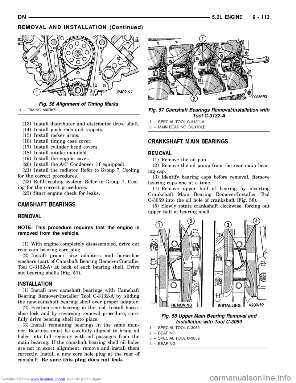
out bearing shells (Fig. 57).
INSTALLATION
(1) Install new camshaft bearings with Camshaft
Bearing Remover/Installer Tool C-3132-A by sliding
the new camshaft bearing shell over proper adapter.
(2) Position rear bearing in the tool. Install horse-
shoe lock and by reversing removal procedure, care-
fully drive bearing shell into place.
(3) Install remaining bearings in the same man-
ner. Bearings must be carefully aligned to bring oil
holes into full register with oil passages from the
main bearing. If the camshaft bearing shell oil holes
are not in exact alignment, remove and install them
correctly. Install a new core hole plug at the rear of
camshaft.Be sure this plug does not leak.
CRANKSHAFT MAIN BEARINGS
REMOVAL
(1) Remove the oil pan.
(2) Remove the oil pump from the rear main bear-
ing cap.
(3) Identify bearing caps before removal. Remove
bearing caps one at a time.
(4) Remove upper half of bearing by inserting
Crankshaft Main Bearing Remover/Installer Tool
C-3059 into the oil hole of crankshaft (Fig. 58).
(5) Slowly rotate crankshaft clockwise, forcing out
upper half of bearing shell.
Fig. 56 Alignment of Timing Marks
1 ± TIMING MARKSFig. 57 Camshaft Bearings Removal/Installation with
Tool C-3132-A
1 ± SPECIAL TOOL C-3132±A
2 ± MAIN BEARING OIL HOLE
Fig. 58 Upper Main Bearing Removal and
Installation with Tool C-3059
1 ± SPECIAL TOOL C-3059
2 ± BEARING
3 ± SPECIAL TOOL C-3059
4 ± BEARING
DN5.2L ENGINE 9 - 113
REMOVAL AND INSTALLATION (Continued)
Page 114 of 193
Downloaded from www.Manualslib.com manuals search engine INSTALLATION
Only one main bearing should be selectively fitted
while all other main bearing caps are properly tight-
ened. All bearing capbolts removed during service pro-
cedures are to be cleaned and oiled before installation.
When installing a new upper bearing shell, slightly
chamfer the sharp edges from the plain side.
(1) Start bearing in place, and insert Crankshaft
Main Bearing Remover/Installer Tool C-3059 into oil
hole of crankshaft (Fig. 58).
(2) Slowly rotate crankshaft counterclockwise slid-
ing the bearing into position. Remove Tool C-3059.
(3)
Install the bearing caps. Clean and oil the bolts.
Tighten the capbolts to 115 N´m (85 ft. lbs.) torque.
(4) Install the oil pump.
(5) Install the oil pan.
(6) Start engine check for leaks.
DISTRIBUTOR DRIVE SHAFT BUSHING
REMOVAL
(1) Remove distributor, refer to Group 8D, Ignition
Systems for the proper procedure.
(2) Remove the intake manifold. Refer to Intake
Manifold in this section for correct procedure.
(3) Insert Distributor Drive Shaft Bushing Puller
Tool C-3052 into old bushing and thread down until a
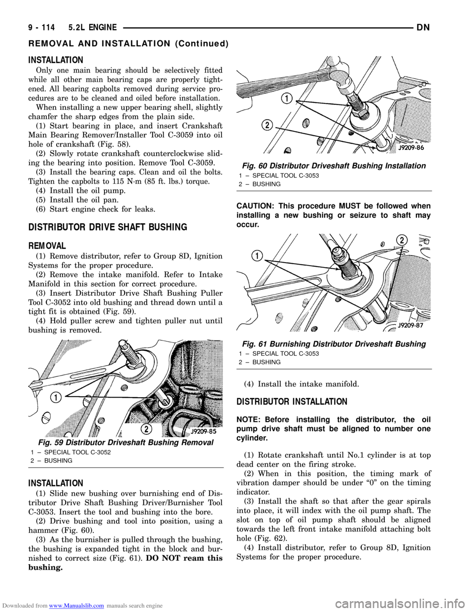
tight fit is obtained (Fig. 59).
(4) Hold puller screw and tighten puller nut until
bushing is removed.
INSTALLATION
(1) Slide new bushing over burnishing end of Dis-
tributor Drive Shaft Bushing Driver/Burnisher Tool
C-3053. Insert the tool and bushing into the bore.
(2) Drive bushing and tool into position, using a
hammer (Fig. 60).
(3) As the burnisher is pulled through the bushing,
the bushing is expanded tight in the block and bur-
nished to correct size (Fig. 61).DO NOT ream this
bushing.CAUTION: This procedure MUST be followed when
installing a new bushing or seizure to shaft may
occur.
(4) Install the intake manifold.
DISTRIBUTOR INSTALLATION
NOTE: Before installing the distributor, the oil
pump drive shaft must be aligned to number one
cylinder.
(1) Rotate crankshaft until No.1 cylinder is at top
dead center on the firing stroke.
(2) When in this position, the timing mark of
vibration damper should be under ª0º on the timing
indicator.
(3) Install the shaft so that after the gear spirals
into place, it will index with the oil pump shaft. The
slot on top of oil pump shaft should be aligned
towards the left front intake manifold attaching bolt
hole (Fig. 62).
(4) Install distributor, refer to Group 8D, Ignition
Systems for the proper procedure.
Fig. 59 Distributor Driveshaft Bushing Removal
1 ± SPECIAL TOOL C-3052
2 ± BUSHING
Fig. 60 Distributor Driveshaft Bushing Installation
1 ± SPECIAL TOOL C-3053
2 ± BUSHING
Fig. 61 Burnishing Distributor Driveshaft Bushing
1 ± SPECIAL TOOL C-3053
2 ± BUSHING
9 - 114 5.2L ENGINEDN
REMOVAL AND INSTALLATION (Continued)
Page 125 of 193
Downloaded from www.Manualslib.com manuals search engine CYLINDER BLOCK
DISASSEMBLE
With Engine removed from vehicle:
(1) Remove the cylinder heads. refer to Cylinder
Head in this section for correct procedure.
(2) Remove the exhaust manifolds. Refer to
Exhaust Manifolds in this section.
(3) Remove the oil pan. Refer to Oil Pan in this
section.
(4) Remove the piston and connecting rod assem-
blies. Refer to Piston and Connecting Rod in this sec-
tion.
(5) Remove the crankshaft. Refer to Crankshaft in
this section.
(6) Remove the core plugs.
ASSEMBLE
(1) Install the core plugs.
(2) Install the crankshaft.
(3) Install the piston and connecting rods.
(4) Install the oil pan.
(5) Install the cylinder heads.
(6) Install the exhaust manifolds.
(7) Install the intake manifold.
(8) Install the engine into the vehicle.
CLEANING AND INSPECTION
CYLINDER HEAD COVER
CLEANING
Clean cylinder head cover gasket surface.
Clean head rail, if necessary.
INSPECTION
Inspect cover for distortion and straighten, if nec-
essary.
Check the gasket for use in head cover installation.
If damaged, use a new gasket.
CYLINDER HEAD ASSEMBLY
CLEANING
Clean all surfaces of cylinder block and cylinder
heads.
Clean cylinder block front and rear gasket surfaces
using a suitable solvent.
INSPECTION
Inspect all surfaces with a straightedge if there is
any reason to suspect leakage. If out-of-flatness
exceeds 0.00075 mm/mm (0.00075 inch/inch) times
the span length in inches in any direction, either
replace head or lightly machine the head surface.
FOR EXAMPLE:A 305 mm (12 inch) span is
0.102 mm (0.004 inch) out-of-flat. The allowable out-
of-flat is 305 X 0.00075 (12 X 0.00075) equals 0.23
mm (0.009 inch). This amount of out-of-flat is accept-
able.
The cylinder head surface finish should be
1.78-3.00 microns (70-125 microinches).
PISTON AND CONNECTING ROD ASSEMBLY
INSPECTION
Check the crankshaft connecting rod journal for
excessive wear, taper and scoring.
Check the cylinder block bore for out-of-round,
taper, scoring and scuffing.
Check the pistons for taper and elliptical shape
before they are fitted into the cylinder bore (Fig. 83).
OIL PAN
CLEANING
Clean the block and pan gasket surfaces.
Trim or remove excess sealant film in the rear
main cap oil pan gasket groove.DO NOT remove
the sealant inside the rear main cap slots.
If present, trim excess sealant from inside the
engine.
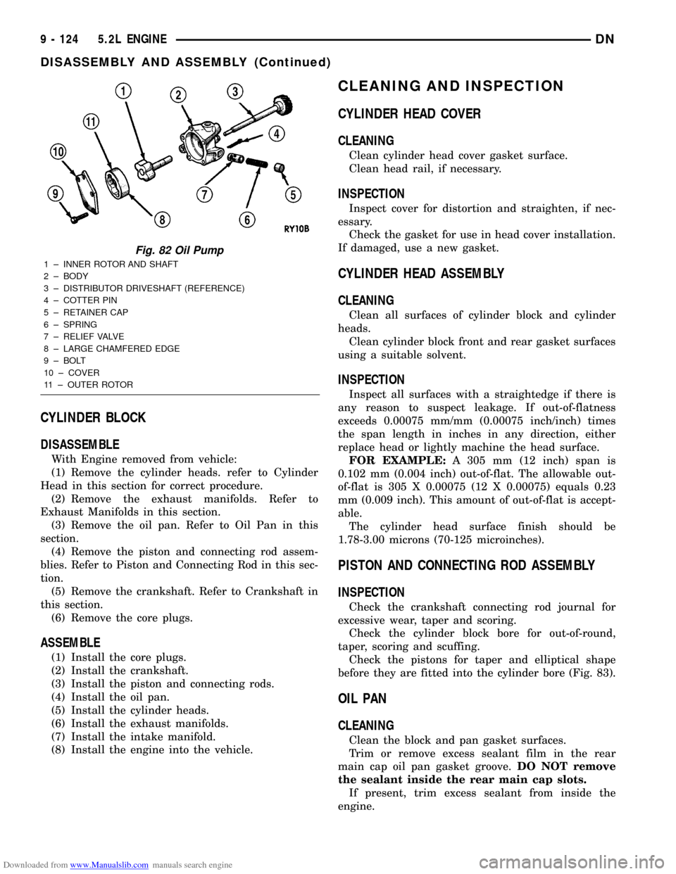
Fig. 82 Oil Pump
1 ± INNER ROTOR AND SHAFT
2 ± BODY
3 ± DISTRIBUTOR DRIVESHAFT (REFERENCE)
4 ± COTTER PIN
5 ± RETAINER CAP
6 ± SPRING
7 ± RELIEF VALVE
8 ± LARGE CHAMFERED EDGE
9 ± BOLT
10 ± COVER
11 ± OUTER ROTOR
9 - 124 5.2L ENGINEDN
DISASSEMBLY AND ASSEMBLY (Continued)
Page 128 of 193
Downloaded from www.Manualslib.com manuals search engine If oil pressure was low and pump is within specifi-
cations, inspect for worn engine bearings or other
reasons for oil pressure loss.
CYLINDER BLOCK
CLEANING
Clean cylinder block thoroughly and check all core
hole plugs for evidence of leaking.
INSPECTION
Examine block for cracks or fractures.
The cylinder walls should be checked for out-of-
round and taper with Cylinder Bore Indicator Tool
C-119. The cylinder block should be bored and honed
with new pistons and rings fitted if:
²The cylinder bores show more than 0.127 mm
(0.005 inch) out-of-round.²The cylinder bores show a taper of more than
0.254 mm (0.010 inch).
²The cylinder walls are badly scuffed or scored.
Boring and honing operation should be closely coor-
dinated with the fitting of pistons and rings so spec-
ified clearances may be maintained.
Refer to Standard Service Procedures in the begin-
ning of this Group for the proper honing of cylinder
bores.
INTAKE MANIFOLD
CLEANING
Clean manifold in solvent and blow dry with com-
pressed air.
Clean cylinder block front and rear gasket surfaces
using a suitable solvent.
The plenum pan rail must be clean and dry (free of
all foreign material).
INSPECTION
Inspect manifold for cracks.
Inspect mating surfaces of manifold for flatness
with a straightedge.
EXHAUST MANIFOLD
CLEANING
Clean mating surfaces on cylinder head and mani-
fold, wash with solvent and blow dry with com-
pressed air.
INSPECTION
Inspect manifold for cracks, Inspect mating sur-
faces of manifold for flatness with a straight edge.
Seal surfaces must be flat within 0.1 mm (0.004 inch)
overall.
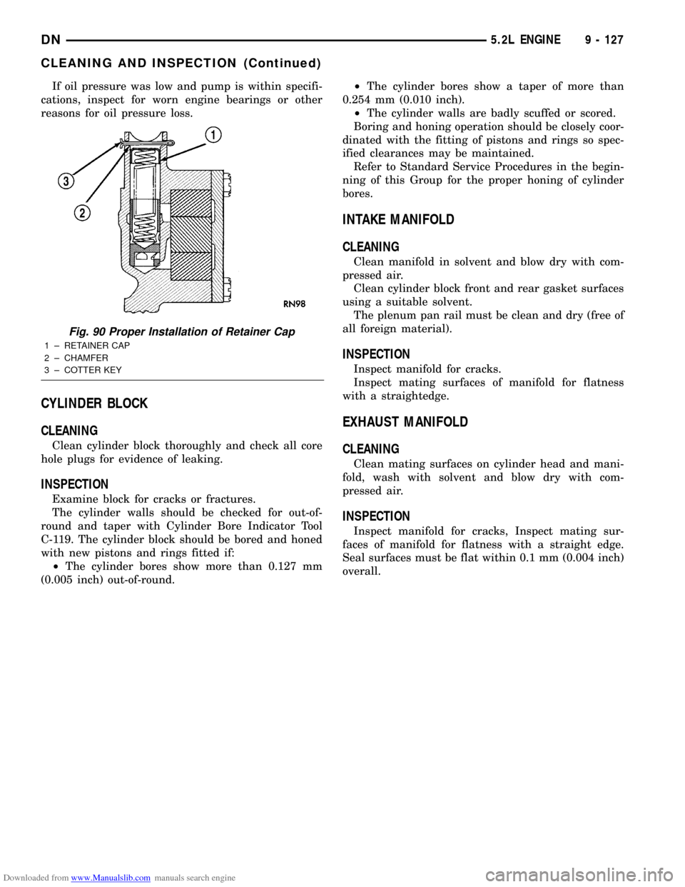
Fig. 90 Proper Installation of Retainer Cap
1 ± RETAINER CAP
2 ± CHAMFER
3 ± COTTER KEY
DN5.2L ENGINE 9 - 127
CLEANING AND INSPECTION (Continued)
Page 133 of 193
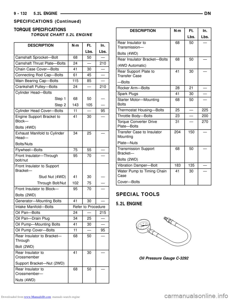
Downloaded from www.Manualslib.com manuals search engine TORQUE SPECIFICATIONS
TORQUE CHART 5.2L ENGINE
DESCRIPTION N´m Ft. In.
Lbs. Lbs.
Camshaft SprocketÐBolt 68 50 Ð
Camshaft Thrust PlateÐBolts 24 Ð 210
Chain Case CoverÐBolts 41 30 Ð
Connecting Rod CapÐBolts 61 45 Ð
Main Bearing CapÐBolts 115 85 Ð
Crankshaft PulleyÐBolts 24 Ð 210
Cylinder HeadÐBolts
Step 1 68 50 Ð
Step 2 143 105 Ð
Cylinder Head CoverÐBolts 11 Ð 95
Engine Support Bracket to
BlockÐ41 30 Ð
Bolts (4WD)
Exhaust Manifold to Cylinder
HeadÐ34 25 Ð
Bolts/Nuts
FlywheelÐBolts 75 55 Ð
Front InsulatorÐThrough
bolt/nut95 70 Ð
Front Insulator to Support
BracketÐ
Stud Nut (4WD) 41 30 Ð
Through Bolt/Nut 102 75 Ð
Front Insulator to BlockÐ 95 70 Ð
Bolts (2WD)
GeneratorÐMounting Bolts 41 30 Ð
Intake ManifoldÐBolts Refer to Procedure
Oil PanÐBolts 24 Ð 215
Oil PanÐDrain Plug 34 25 Ð
Oil PumpÐMounting Bolts 41 30 Ð
Oil Pump CoverÐBolts 11 Ð 95
Rear Insulator to BracketÐ
Through68 50 Ð
Bolt (2WD)
Rear Insulator to
Crossmember41 30 Ð
Support BracketÐNut (2WD)
Rear Insulator to
CrossmemberÐ68 50 Ð
Nuts (4WD)
DESCRIPTION N´m Ft. In.
Lbs. Lbs.
Rear Insulator to
TransmissionÐ68 50 Ð
Bolts (4WD)
Rear Insulator BracketÐBolts 68 50 Ð
(4WD Automatic)
Rear Support Plate to
Transfer Case41 30 Ð
ÐBolts
Rocker ArmÐBolts 28 21 Ð
Spark Plugs 41 30 Ð
Starter MotorÐMounting
Bolts68 50 Ð
Thermostat HousingÐBolts 25 Ð 225
Throttle BodyÐBolts 23 Ð 200
Torque Converter Drive
PlateÐBolts31 Ð 270
Transfer Case to Insulator
Mounting204 150 Ð
PlateÐNuts
Transmission Support
BracketÐ68 50 Ð
Bolts (2WD)
Vibration DamperÐBolt 183 135 Ð
Water Pump to Timing Chain
Case41 30 Ð
CoverÐBolts
SPECIAL TOOLS
5.2L ENGINE
Oil Pressure Gauge C-3292
9 - 132 5.2L ENGINEDN
SPECIFICATIONS (Continued)
Page 136 of 193
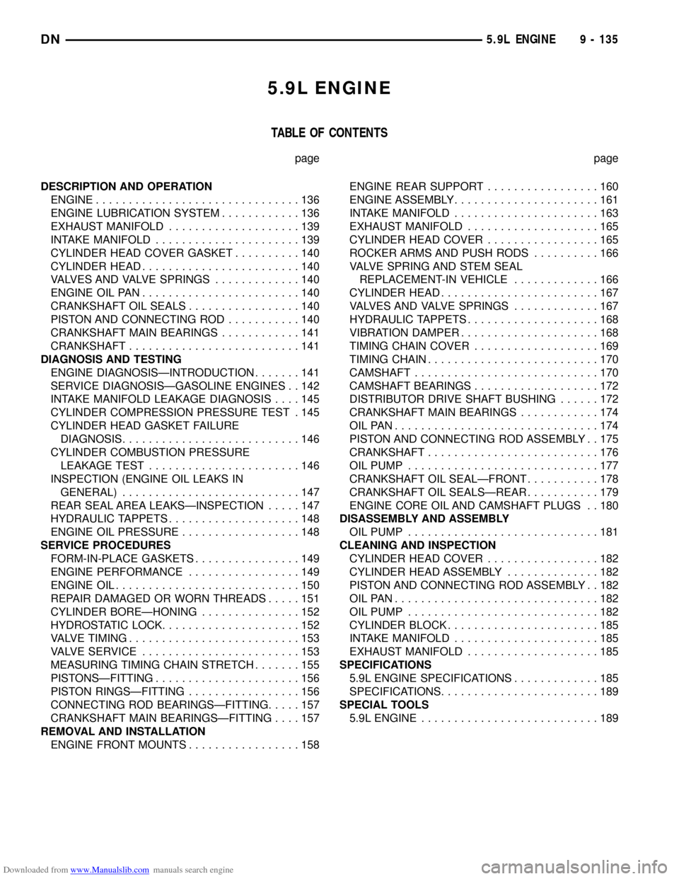
Downloaded from www.Manualslib.com manuals search engine 5.9L ENGINE
TABLE OF CONTENTS
page page
DESCRIPTION AND OPERATION
ENGINE...............................136
ENGINE LUBRICATION SYSTEM............136
EXHAUST MANIFOLD....................139
INTAKE MANIFOLD......................139
CYLINDER HEAD COVER GASKET..........140
CYLINDER HEAD........................140
VALVES AND VALVE SPRINGS.............140
ENGINE OIL PAN........................140
CRANKSHAFT OIL SEALS.................140
PISTON AND CONNECTING ROD...........140
CRANKSHAFT MAIN BEARINGS............141
CRANKSHAFT..........................141
DIAGNOSIS AND TESTING
ENGINE DIAGNOSISÐINTRODUCTION.......141
SERVICE DIAGNOSISÐGASOLINE ENGINES . . 142
INTAKE MANIFOLD LEAKAGE DIAGNOSIS....145
CYLINDER COMPRESSION PRESSURE TEST . 145
CYLINDER HEAD GASKET FAILURE
DIAGNOSIS...........................146
CYLINDER COMBUSTION PRESSURE
LEAKAGE TEST.......................146
INSPECTION (ENGINE OIL LEAKS IN
GENERAL)...........................147
REAR SEAL AREA LEAKSÐINSPECTION.....147
HYDRAULIC TAPPETS....................148
ENGINE OIL PRESSURE..................148
SERVICE PROCEDURES
FORM-IN-PLACE GASKETS................149
ENGINE PERFORMANCE.................149
ENGINE OIL............................150
REPAIR DAMAGED OR WORN THREADS.....151
CYLINDER BOREÐHONING...............152
HYDROSTATIC LOCK.....................152
VALVE TIMING..........................153
VALVE SERVICE........................153
MEASURING TIMING CHAIN STRETCH.......155
PISTONSÐFITTING......................156
PISTON RINGSÐFITTING.................156
CONNECTING ROD BEARINGSÐFITTING.....157
CRANKSHAFT MAIN BEARINGSÐFITTING....157
REMOVAL AND INSTALLATION
ENGINE FRONT MOUNTS.................158ENGINE REAR SUPPORT.................160
ENGINE ASSEMBLY......................161
INTAKE MANIFOLD......................163
EXHAUST MANIFOLD....................165
CYLINDER HEAD COVER.................165
ROCKER ARMS AND PUSH RODS..........166
VALVE SPRING AND STEM SEAL
REPLACEMENT-IN VEHICLE.............166
CYLINDER HEAD........................167
VALVES AND VALVE SPRINGS.............167
HYDRAULIC TAPPETS....................168
VIBRATION DAMPER.....................168
TIMING CHAIN COVER...................169
TIMING CHAIN..........................170
CAMSHAFT............................170
CAMSHAFT BEARINGS...................172
DISTRIBUTOR DRIVE SHAFT BUSHING......172
CRANKSHAFT MAIN BEARINGS............174
OILPAN...............................174
PISTON AND CONNECTING ROD ASSEMBLY . . 175
CRANKSHAFT..........................176
OIL PUMP.............................177
CRANKSHAFT OIL SEALÐFRONT...........178
CRANKSHAFT OIL SEALSÐREAR...........179
ENGINE CORE OIL AND CAMSHAFT PLUGS . . 180
DISASSEMBLY AND ASSEMBLY
OIL PUMP.............................181
CLEANING AND INSPECTION
CYLINDER HEAD COVER.................182
CYLINDER HEAD ASSEMBLY..............182
PISTON AND CONNECTING ROD ASSEMBLY . . 182
OILPAN...............................182
OIL PUMP.............................182
CYLINDER BLOCK.......................185
INTAKE MANIFOLD......................185
EXHAUST MANIFOLD....................185
SPECIFICATIONS
5.9L ENGINE SPECIFICATIONS.............185
SPECIFICATIONS........................189
SPECIAL TOOLS
5.9L ENGINE...........................189
DN5.9L ENGINE 9 - 135
Page 140 of 193
Downloaded from www.Manualslib.com manuals search engine EXHAUST MANIFOLD
DESCRIPTION
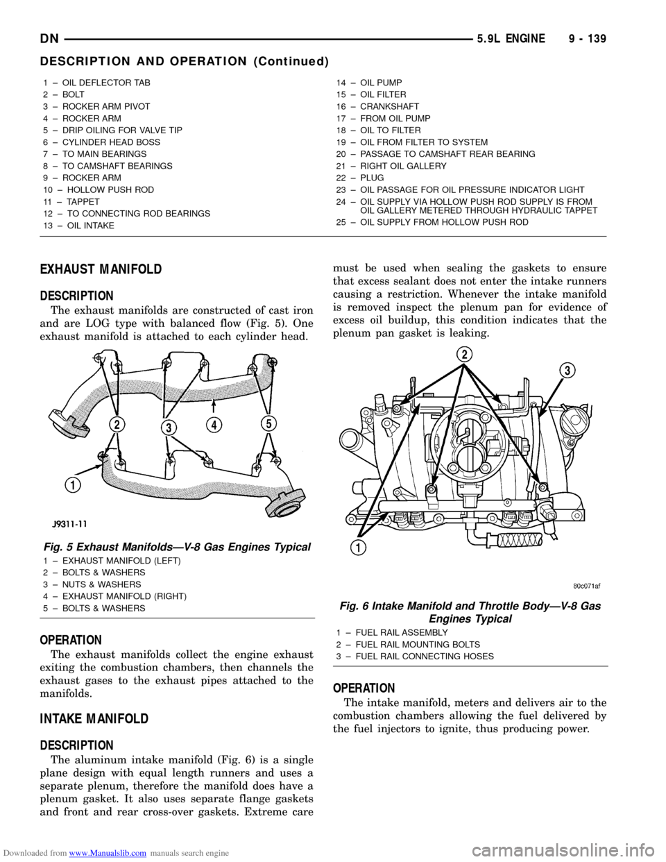
The exhaust manifolds are constructed of cast iron
and are LOG type with balanced flow (Fig. 5). One
exhaust manifold is attached to each cylinder head.
OPERATION
The exhaust manifolds collect the engine exhaust
exiting the combustion chambers, then channels the
exhaust gases to the exhaust pipes attached to the
manifolds.
INTAKE MANIFOLD
DESCRIPTION
The aluminum intake manifold (Fig. 6) is a single
plane design with equal length runners and uses a
separate plenum, therefore the manifold does have a
plenum gasket. It also uses separate flange gaskets
and front and rear cross-over gaskets. Extreme caremust be used when sealing the gaskets to ensure
that excess sealant does not enter the intake runners
causing a restriction. Whenever the intake manifold
is removed inspect the plenum pan for evidence of
excess oil buildup, this condition indicates that the
plenum pan gasket is leaking.
OPERATION
The intake manifold, meters and delivers air to the
combustion chambers allowing the fuel delivered by
the fuel injectors to ignite, thus producing power.
1 ± OIL DEFLECTOR TAB
2 ± BOLT
3 ± ROCKER ARM PIVOT
4 ± ROCKER ARM
5 ± DRIP OILING FOR VALVE TIP
6 ± CYLINDER HEAD BOSS
7 ± TO MAIN BEARINGS
8 ± TO CAMSHAFT BEARINGS
9 ± ROCKER ARM
10 ± HOLLOW PUSH ROD
11 ± TAPPET
12 ± TO CONNECTING ROD BEARINGS
13 ± OIL INTAKE14 ± OIL PUMP
15 ± OIL FILTER
16 ± CRANKSHAFT
17 ± FROM OIL PUMP
18 ± OIL TO FILTER
19 ± OIL FROM FILTER TO SYSTEM
20 ± PASSAGE TO CAMSHAFT REAR BEARING
21 ± RIGHT OIL GALLERY
22 ± PLUG
23 ± OIL PASSAGE FOR OIL PRESSURE INDICATOR LIGHT
24 ± OIL SUPPLY VIA HOLLOW PUSH ROD SUPPLY IS FROM
OIL GALLERY METERED THROUGH HYDRAULIC TAPPET
25 ± OIL SUPPLY FROM HOLLOW PUSH ROD
Fig. 5 Exhaust ManifoldsÐV-8 Gas Engines Typical
1 ± EXHAUST MANIFOLD (LEFT)
2 ± BOLTS & WASHERS
3 ± NUTS & WASHERS
4 ± EXHAUST MANIFOLD (RIGHT)
5 ± BOLTS & WASHERS
Fig. 6 Intake Manifold and Throttle BodyÐV-8 Gas
Engines Typical
1 ± FUEL RAIL ASSEMBLY
2 ± FUEL RAIL MOUNTING BOLTS
3 ± FUEL RAIL CONNECTING HOSES
DN5.9L ENGINE 9 - 139
DESCRIPTION AND OPERATION (Continued)
Page 142 of 193
Downloaded from www.Manualslib.com manuals search engine CRANKSHAFT MAIN BEARINGS
DESCRIPTION
Main bearings are located in the cylinder block.
One half of the main bearing is located in the crank-
shaft main bore the other half of the matching bear-
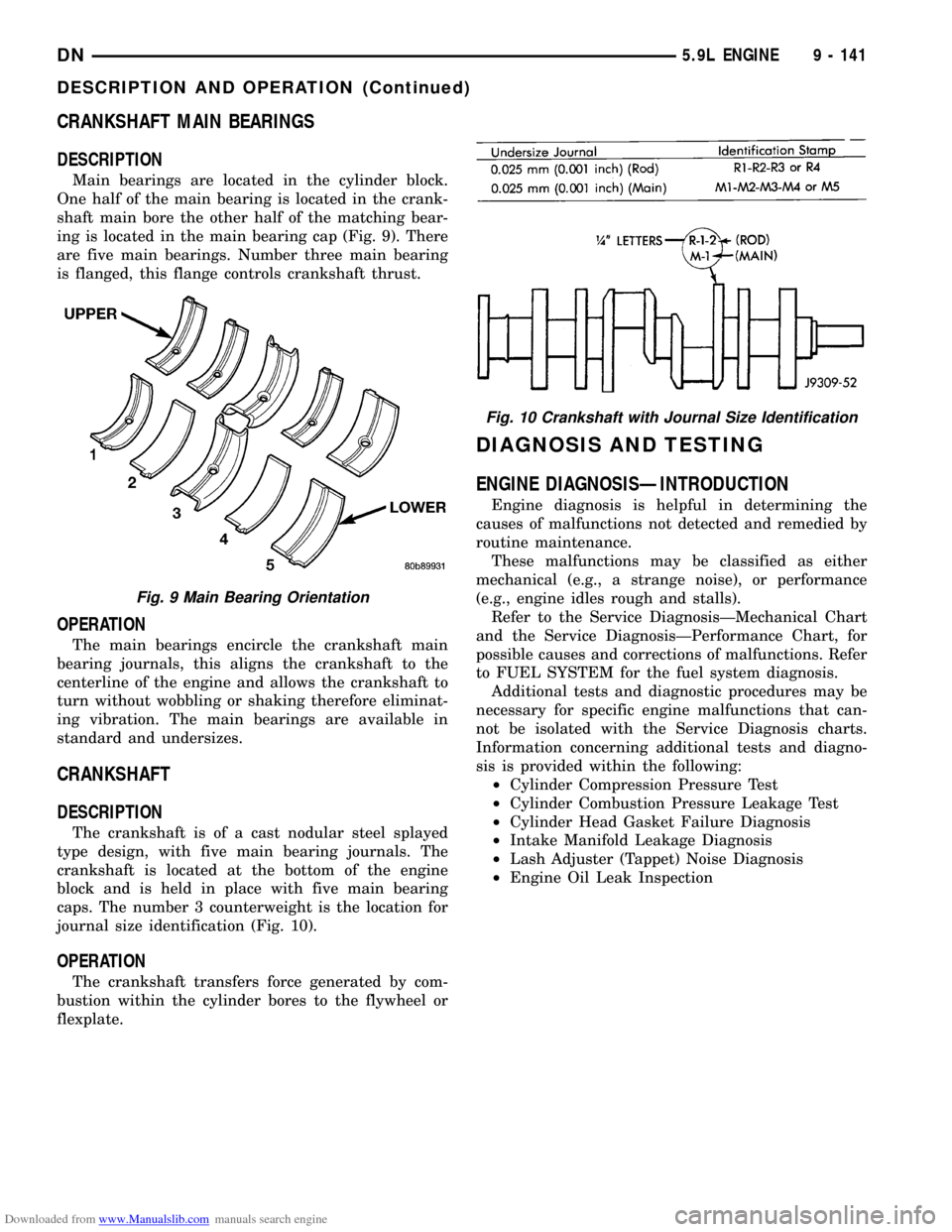
ing is located in the main bearing cap (Fig. 9). There
are five main bearings. Number three main bearing
is flanged, this flange controls crankshaft thrust.
OPERATION
The main bearings encircle the crankshaft main
bearing journals, this aligns the crankshaft to the
centerline of the engine and allows the crankshaft to
turn without wobbling or shaking therefore eliminat-
ing vibration. The main bearings are available in
standard and undersizes.
CRANKSHAFT
DESCRIPTION
The crankshaft is of a cast nodular steel splayed
type design, with five main bearing journals. The
crankshaft is located at the bottom of the engine
block and is held in place with five main bearing
caps. The number 3 counterweight is the location for
journal size identification (Fig. 10).
OPERATION
The crankshaft transfers force generated by com-
bustion within the cylinder bores to the flywheel or
flexplate.
DIAGNOSIS AND TESTING
ENGINE DIAGNOSISÐINTRODUCTION
Engine diagnosis is helpful in determining the
causes of malfunctions not detected and remedied by
routine maintenance.
These malfunctions may be classified as either
mechanical (e.g., a strange noise), or performance
(e.g., engine idles rough and stalls).
Refer to the Service DiagnosisÐMechanical Chart
and the Service DiagnosisÐPerformance Chart, for
possible causes and corrections of malfunctions. Refer
to FUEL SYSTEM for the fuel system diagnosis.
Additional tests and diagnostic procedures may be
necessary for specific engine malfunctions that can-
not be isolated with the Service Diagnosis charts.
Information concerning additional tests and diagno-
sis is provided within the following:
²Cylinder Compression Pressure Test
²Cylinder Combustion Pressure Leakage Test
²Cylinder Head Gasket Failure Diagnosis
²Intake Manifold Leakage Diagnosis
²Lash Adjuster (Tappet) Noise Diagnosis
²Engine Oil Leak Inspection
Fig. 9 Main Bearing Orientation
Fig. 10 Crankshaft with Journal Size Identification
DN5.9L ENGINE 9 - 141
DESCRIPTION AND OPERATION (Continued)
Page 144 of 193
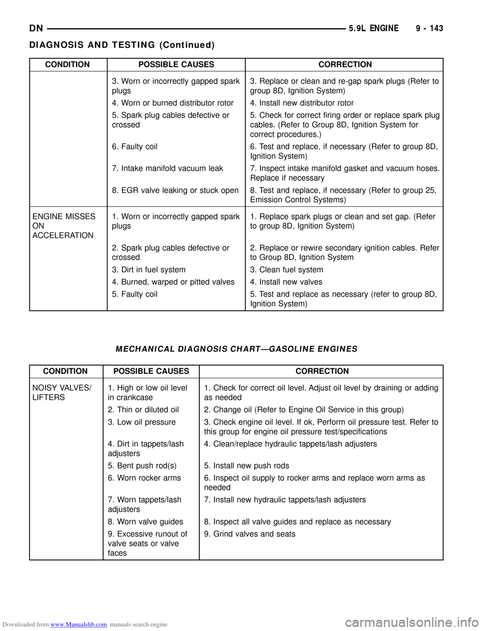
Downloaded from www.Manualslib.com manuals search engine CONDITION POSSIBLE CAUSES CORRECTION
3. Worn or incorrectly gapped spark
plugs3. Replace or clean and re-gap spark plugs (Refer to
group 8D, Ignition System)
4. Worn or burned distributor rotor 4. Install new distributor rotor
5. Spark plug cables defective or
crossed5. Check for correct firing order or replace spark plug
cables. (Refer to Group 8D, Ignition System for
correct procedures.)
6. Faulty coil 6. Test and replace, if necessary (Refer to group 8D,
Ignition System)
7. Intake manifold vacuum leak 7. Inspect intake manifold gasket and vacuum hoses.
Replace if necessary
8. EGR valve leaking or stuck open 8. Test and replace, if necessary (Refer to group 25,
Emission Control Systems)
ENGINE MISSES
ON
ACCELERATION1. Worn or incorrectly gapped spark
plugs1. Replace spark plugs or clean and set gap. (Refer
to group 8D, Ignition System)
2. Spark plug cables defective or
crossed2. Replace or rewire secondary ignition cables. Refer
to Group 8D, Ignition System
3. Dirt in fuel system 3. Clean fuel system
4. Burned, warped or pitted valves 4. Install new valves
5. Faulty coil 5. Test and replace as necessary (refer to group 8D,
Ignition System)
MECHANICAL DIAGNOSIS CHARTÐGASOLINE ENGINES
CONDITION POSSIBLE CAUSES CORRECTION
NOISY VALVES/
LIFTERS1. High or low oil level
in crankcase1. Check for correct oil level. Adjust oil level by draining or adding
as needed
2. Thin or diluted oil 2. Change oil (Refer to Engine Oil Service in this group)
3. Low oil pressure 3. Check engine oil level. If ok, Perform oil pressure test. Refer to
this group for engine oil pressure test/specifications
4. Dirt in tappets/lash
adjusters4. Clean/replace hydraulic tappets/lash adjusters
5. Bent push rod(s) 5. Install new push rods
6. Worn rocker arms 6. Inspect oil supply to rocker arms and replace worn arms as
needed
7. Worn tappets/lash
adjusters7. Install new hydraulic tappets/lash adjusters
8. Worn valve guides 8. Inspect all valve guides and replace as necessary
9. Excessive runout of
valve seats or valve
faces9. Grind valves and seats
DN5.9L ENGINE 9 - 143
DIAGNOSIS AND TESTING (Continued)
Page 146 of 193
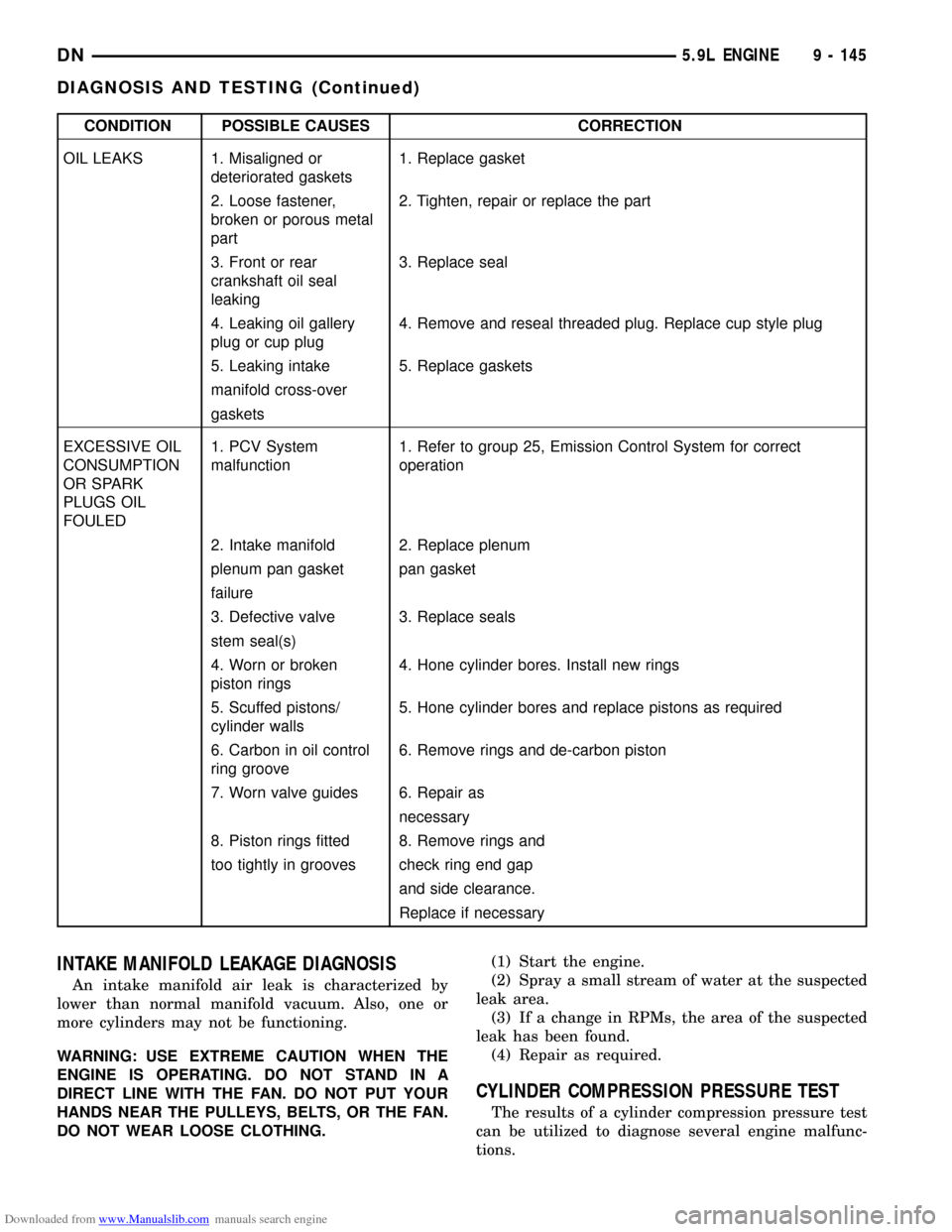
Downloaded from www.Manualslib.com manuals search engine CONDITION POSSIBLE CAUSES CORRECTION
OIL LEAKS 1. Misaligned or
deteriorated gaskets1. Replace gasket
2. Loose fastener,
broken or porous metal
part2. Tighten, repair or replace the part
3. Front or rear
crankshaft oil seal
leaking3. Replace seal
4. Leaking oil gallery
plug or cup plug4. Remove and reseal threaded plug. Replace cup style plug
5. Leaking intake 5. Replace gaskets
manifold cross-over
gaskets
EXCESSIVE OIL
CONSUMPTION
OR SPARK
PLUGS OIL
FOULED1. PCV System
malfunction1. Refer to group 25, Emission Control System for correct
operation
2. Intake manifold 2. Replace plenum
plenum pan gasket pan gasket
failure
3. Defective valve 3. Replace seals
stem seal(s)
4. Worn or broken
piston rings4. Hone cylinder bores. Install new rings
5. Scuffed pistons/
cylinder walls5. Hone cylinder bores and replace pistons as required
6. Carbon in oil control
ring groove6. Remove rings and de-carbon piston
7. Worn valve guides 6. Repair as
necessary
8. Piston rings fitted 8. Remove rings and
too tightly in grooves check ring end gap
and side clearance.
Replace if necessary
INTAKE MANIFOLD LEAKAGE DIAGNOSIS
An intake manifold air leak is characterized by
lower than normal manifold vacuum. Also, one or
more cylinders may not be functioning.
WARNING: USE EXTREME CAUTION WHEN THE
ENGINE IS OPERATING. DO NOT STAND IN A
DIRECT LINE WITH THE FAN. DO NOT PUT YOUR
HANDS NEAR THE PULLEYS, BELTS, OR THE FAN.
DO NOT WEAR LOOSE CLOTHING.(1) Start the engine.
(2) Spray a small stream of water at the suspected
leak area.
(3) If a change in RPMs, the area of the suspected
leak has been found.
(4) Repair as required.
CYLINDER COMPRESSION PRESSURE TEST
The results of a cylinder compression pressure test
can be utilized to diagnose several engine malfunc-
tions.
DN5.9L ENGINE 9 - 145
DIAGNOSIS AND TESTING (Continued)