Axle bearing DODGE DURANGO 1998 1.G Workshop Manual
[x] Cancel search | Manufacturer: DODGE, Model Year: 1998, Model line: DURANGO, Model: DODGE DURANGO 1998 1.GPages: 193, PDF Size: 5.65 MB
Page 65 of 193

Downloaded from www.Manualslib.com manuals search engine INSTALLATION
(1) Clean the oil pan gasket mating surface of the
bedplate and oil pan.
(2) Position the oil pan gasket and pickup tube
with new o-ring. Install the mounting bolt and nuts.
Tighten bolt and nuts to 28 N´m (20 ft. lbs.).
(3) Position the oil pan and install the mounting
bolts. Tighten the mounting bolts to 15 N´m (11 ft.
lbs.) in the sequence shown (Fig. 110).
(4) Install structural dust cover.
(5) Install oil filter.
(6) Install front axle. Refer to DIFFERENTIAL
AND DRIVELINE.
(7) Lower vehicle.
(8) Fill engine oil.
(9) Start engine check for leaks.
PISTON AND CONNECTING ROD
REMOVAL
(1) Disconnect negative cable from battery.
(2) Remove the following components: (Refer to
procedures in this section)
²Oil pan and gasket/windage tray.
²Cylinder head covers.
²Timing chain cover.
²Cylinder head(s).
(3) If necessary, remove top ridge of cylinder bores
with a reliable ridge reamer before removing pistons
from cylinder block.Be sure to keep tops of pis-
tons covered during this operation.Pistons and
connecting rods must be removed from top of cylinder
block. When removing piston and connecting rod
assemblies from the engine, rotate crankshaft so the
each connecting rod is centered in cylinder bore.
CAUTION: DO NOT use a number stamp or a punch
to mark connecting rods or caps, as damage to
connecting rods could occur
NOTE: Connecting rods and bearing caps are not
interchangeable and should be marked before
removing to ensure correct reassembly.
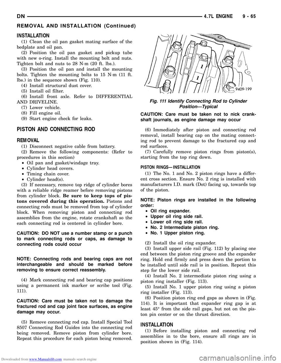
(4) Mark connecting rod and bearing cap positions
using a permanent ink marker or scribe tool (Fig.
111).
CAUTION: Care must be taken not to damage the
fractured rod and cap joint face surfaces, as engine
damage may occur.
(5) Remove connecting rod cap. Install Special Tool
8507 Connecting Rod Guides into the connecting rod
being removed. Remove piston from cylinder bore.
Repeat this procedure for each piston being removed.CAUTION: Care must be taken not to nick crank-
shaft journals, as engine damage may occur
(6) Immediately after piston and connecting rod
removal, install bearing cap on the mating connect-
ing rod to prevent damage to the fractured cap and
rod surfaces.
(7) Carefully remove piston rings from piston(s),
starting from the top ring down.
PISTON RINGSÐINSTALLATION
(1) The No. 1 and No. 2 piston rings have a differ-
ent cross section. Ensure No. 2 ring is installed with
manufacturers I.D. mark (Dot) facing up, towards top
of the piston.
NOTE: Piston rings are installed in the following
order:
²Oil ring expander.
²Upper oil ring side rail.
²Lower oil ring side rail.
²No. 2 Intermediate piston ring.
²No. 1 Upper piston ring.
(2) Install the oil ring expander.
(3) Install upper side rail (Fig. 112) by placing one
end between the piston ring groove and the expander
ring. Hold end firmly and press down the portion to
be installed until side rail is in position. Repeat this
step for the lower side rail.
(4) Install No. 2 intermediate piston ring using a
piston ring installer (Fig. 113).
(5) Install No. 1 upper piston ring using a piston
ring installer (Fig. 113).
(6) Position piston ring end gaps as shown in (Fig.
114). It is important that expander ring gap is at
least 45É from the side rail gaps, but not on the pis-
ton pin center or on the thrust direction.
INSTALLATION
(1) Before installing piston and connecting rod
assemblies in to the bore, ensure all rings are in
position shown in (Fig. 114).
Fig. 111 Identify Connecting Rod to Cylinder
PositionÐTypical
DN4.7L ENGINE 9 - 65
REMOVAL AND INSTALLATION (Continued)
Page 100 of 193

Downloaded from www.Manualslib.com manuals search engine CONNECTING ROD BEARINGSÐFITTING
Fit all rods on a bank until completed. DO NOT
alternate from one bank to another, because connect-
ing rods and pistons are not interchangeable from
one bank to another.
The bearing caps are not interchangeable and
should be marked at removal to ensure correct
assembly.
Each bearing cap has a small V-groove across the
parting face. When installing the lower bearing shell,
make certain that the V-groove in the shell is in line
with the V-groove in the cap. This provides lubrica-
tion of the cylinder wall in the opposite bank.The bearing shells must be installed so that the
tangs are in the machined grooves in the rods and
caps.
Limits of taper or out-of-round on any crankshaft
journals should be held to 0.025 mm (0.001 inch).
Bearings are available in 0.025 mm (0.001 inch),
0.051 mm (0.002 inch), 0.076 mm (0.003 inch), 0.254
mm (0.010 inch) and 0.305 mm (0.012 inch) under-
size.Install the bearings in pairs. DO NOT use a
new bearing half with an old bearing half. DO
NOT file the rods or bearing caps.
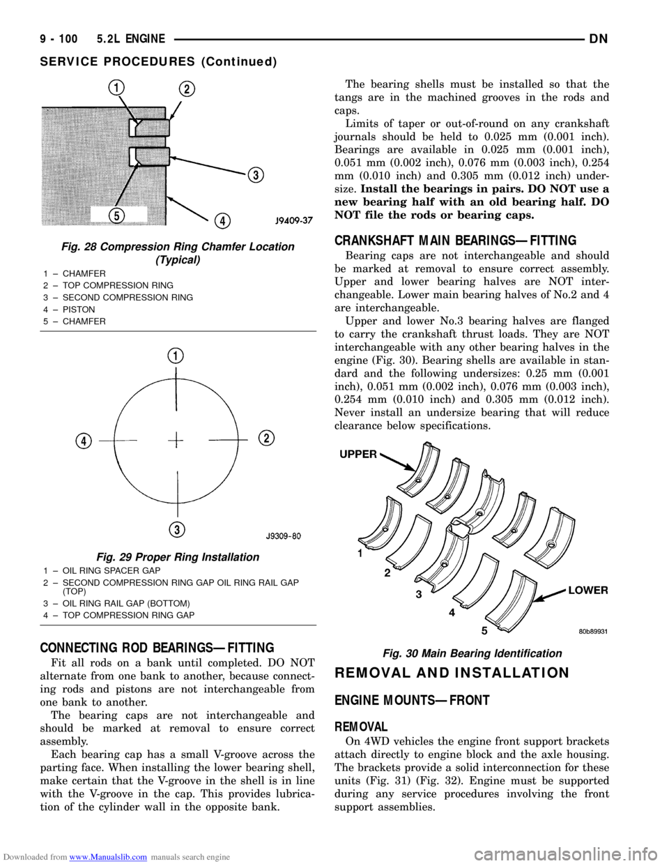
CRANKSHAFT MAIN BEARINGSÐFITTING
Bearing caps are not interchangeable and should
be marked at removal to ensure correct assembly.
Upper and lower bearing halves are NOT inter-
changeable. Lower main bearing halves of No.2 and 4
are interchangeable.
Upper and lower No.3 bearing halves are flanged
to carry the crankshaft thrust loads. They are NOT
interchangeable with any other bearing halves in the
engine (Fig. 30). Bearing shells are available in stan-
dard and the following undersizes: 0.25 mm (0.001
inch), 0.051 mm (0.002 inch), 0.076 mm (0.003 inch),
0.254 mm (0.010 inch) and 0.305 mm (0.012 inch).
Never install an undersize bearing that will reduce
clearance below specifications.
REMOVAL AND INSTALLATION
ENGINE MOUNTSÐFRONT
REMOVAL
On 4WD vehicles the engine front support brackets
attach directly to engine block and the axle housing.
The brackets provide a solid interconnection for these
units (Fig. 31) (Fig. 32). Engine must be supported
during any service procedures involving the front
support assemblies.
Fig. 28 Compression Ring Chamfer Location
(Typical)
1 ± CHAMFER
2 ± TOP COMPRESSION RING
3 ± SECOND COMPRESSION RING
4 ± PISTON
5 ± CHAMFER
Fig. 29 Proper Ring Installation
1 ± OIL RING SPACER GAP
2 ± SECOND COMPRESSION RING GAP OIL RING RAIL GAP
(TOP)
3 ± OIL RING RAIL GAP (BOTTOM)
4 ± TOP COMPRESSION RING GAP
Fig. 30 Main Bearing Identification
9 - 100 5.2L ENGINEDN
SERVICE PROCEDURES (Continued)
Page 175 of 193

Downloaded from www.Manualslib.com manuals search engine CRANKSHAFT MAIN BEARINGS
REMOVAL
(1) Remove the oil pan.
(2) Remove the oil pump from the rear main bear-
ing cap.
(3) Identify bearing caps before removal. Remove
bearing caps one at a time.
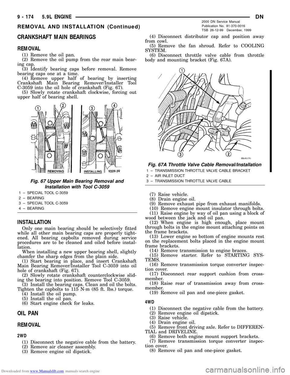
(4) Remove upper half of bearing by inserting
Crankshaft Main Bearing Remover/Installer Tool
C-3059 into the oil hole of crankshaft (Fig. 67).
(5) Slowly rotate crankshaft clockwise, forcing out
upper half of bearing shell.
INSTALLATION
Only one main bearing should be selectively fitted
while all other main bearing caps are properly tight-
ened. All bearing capbolts removed during service
procedures are to be cleaned and oiled before instal-
lation.
When installing a new upper bearing shell, slightly
chamfer the sharp edges from the plain side.
(1) Start bearing in place, and insert Crankshaft
Main Bearing Remover/Installer Tool C-3059 into oil
hole of crankshaft (Fig. 67).
(2) Slowly rotate crankshaft counterclockwise slid-
ing the bearing into position. Remove Tool C-3059.
(3) Install the bearing caps. Clean and oil the bolts.
Tighten the capbolts to 115 N´m (85 ft. lbs.) torque.
(4) Install the oil pump.
(5) Install the oil pan.
(6) Start engine check for leaks.
OIL PAN
REMOVAL
2WD
(1) Disconnect the negative cable from the battery.
(2) Remove air cleaner assembly.
(3) Remove engine oil dipstick.(4) Disconnect distributor cap and position away
from cowl.
(5) Remove the fan shroud. Refer to COOLING
SYSTEM.
(6) Disconnect throttle valve cable from throttle
body and mounting bracket (Fig. 67A).
(7) Raise vehicle.
(8) Drain engine oil.
(9) Remove exhaust pipe from exhaust manifolds.
(10) Remove engine mount insulator through bolts.
(11) Raise engine by way of oil pan using a block of
wood between the jack and oil pan.
(12) When engine is high enough, place mount
through bolts in the engine mount attaching points on
the frame brackets.
(13) Lower engine so bottom of engine mounts rest
on the replacement bolts placed in the engine mount
frame brackets.
(14) Remove transmission to engine braces.
(15) Remove starter. Refer to STARTING SYS-
TEMS.
(16) Remove transmission torque converter inspec-
tion cover.
(17) Disconnect rear support cushion from cross-
member.
(18) Raise rear of transmission away from cross-
member.
(19) Remove oil pan and one-piece gasket.
4WD
(1) Disconnect the negative cable from the battery.
(2) Remove engine oil dipstick.
(3) Raise vehicle.
(4) Drain engine oil.
(5) Remove front driving axle. Refer to DIFFEREN-
TIAL and DRIVELINE.
(6) Remove both engine mount support brackets.
(7) Remove transmission torque converter inspec-
tion cover.
(8) Remove oil pan and one-piece gasket.
Fig. 67 Upper Main Bearing Removal and
Installation with Tool C-3059
1 ± SPECIAL TOOL C-3059
2 ± BEARING
3 ± SPECIAL TOOL C-3059
4 ± BEARING
Fig. 67A Throttle Valve Cable Removal/Installation
1 ± TRANSMISSION THROTTLE VALVE CABLE BRACKET
2 ± AIR INLET DUCT
3 ± TRANSMISSION THROTTLE VALVE CABLE
9 - 174 5.9L ENGINEDN
REMOVAL AND INSTALLATION (Continued)
2000 DN Service Manual
Publication No. 81-370-0016
TSB 26-12-99 December, 1999
Page 176 of 193

Downloaded from www.Manualslib.com manuals search engine INSTALLATION
2WD
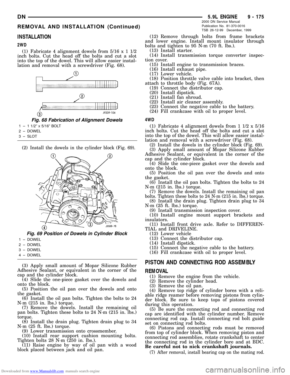
(1) Fabricate 4 alignment dowels from 5/16x11/2
inch bolts. Cut the head off the bolts and cut a slot
into the top of the dowel. This will allow easier instal-
lation and removal with a screwdriver (Fig. 68).
(2) Install the dowels in the cylinder block (Fig. 69).
(3) Apply small amount of Mopar Silicone Rubber
Adhesive Sealant, or equivalent in the corner of the
cap and the cylinder block.
(4) Slide the one-piece gasket over the dowels and
onto the block.
(5) Position the oil pan over the dowels and onto
the gasket.
(6) Install the oil pan bolts. Tighten the bolts to 24
N´m (215 in. lbs.) torque.
(7) Remove the dowels. Install the remaining oil
pan bolts. Tighten these bolts to 24 N´m (215 in. lbs.)
torque.
(8) Install the drain plug. Tighten drain plug to 34
N´m (25 ft. lbs.) torque.
(9) Lower transmission onto crossmember.
(10) Install rear support cushion mounting bolts.
Tighten bolts 28 N´m (250 in. lbs.).
(11) Raise engine by way of oil pan with a wood
block placed between jack and oil pan.(12) Remove through bolts from frame brackets
and lower engine. Install mount insulator through
bolts and tighten to 95 N´m (70 ft. lbs.).
(13) Install starter.
(14) Install transmission torque converter inspec-
tion cover.
(15) Install engine to transmission braces.
(16) Install exhaust pipe.
(17) Lower vehicle.
(18) Position throttle valve cable into bracket, then
attach to throttle body (Fig. 67A).
(19) Connect the distributor cap.
(20) Install dipstick.
(21) Install fan shroud.
(22) Install air cleaner assembly.
(23) Connect the negative cable to the battery.
(24) Fill crankcase with oil to proper level.
4WD
(1) Fabricate 4 alignment dowels from 1 1/2 x 5/16
inch bolts. Cut the head off the bolts and cut a slot
into the top of the dowel. This will allow easier instal-
lation and removal with a screwdriver (Fig. 68).
(2) Install the dowels in the cylinder block (Fig. 69).(3) Apply small amount of Mopar Silicone Rubber
Adhesive Sealant, or equivalent in the corner of the
cap and the cylinder block.
(4) Slide the one-piece gasket over the dowels and
onto the block.
(5) Position the oil pan over the dowels and onto
the gasket.
(6) Install the oil pan bolts. Tighten the bolts to 24
N´m (215 in. lbs.) torque.
(7)
Remove the dowels. Install the remaining oil pan
bolts. Tighten these bolts to 24 N´m (215 in. lbs.) torque.
(8) Install the drain plug. Tighten drain plug to 34
N´m (25 ft. lbs.) torque.
(9) Install transmission inspection cover.
(10) Install engine mount support brackets and
insulators.
(11) Install front drive axle. Refer to DIFFEREN-
TIAL and DRIVELINE.
(12) Lower vehicle
(13) Connect the distributor cap.
(14) Install dipstick.
(15) Connect the negative cable to the battery.
(16) Fill crankcase with oil to proper level.
PISTON AND CONNECTING ROD ASSEMBLY
REMOVAL
(1) Remove the engine from the vehicle.
(2) Remove the cylinder head.
(3) Remove the oil pan.
(4) Remove top ridge of cylinder bores with a reli-
able ridge reamer before removing pistons from cylin-
der block. Be sure to keep tops of pistons covered
during this operation.
(5) Be sure the connecting rod and connecting rod
cap are identified with the cylinder number. Remove
connecting rod cap. Install connecting rod bolt guide
set on connecting rod bolts.
(6) Pistons and connecting rods must be removed
from top of cylinder block. When removing piston and
connecting rod assemblies, rotate crankshaft to center
the connecting rod in the cylinder bore and at BDC.
Be careful not to nick crankshaft journals.
(7) After removal, install bearing cap on the mating rod.
Fig. 68 Fabrication of Alignment Dowels
1 ± 1 1/2º x 5/16º BOLT
2 ± DOWEL
3 ± SLOT
Fig. 69 Position of Dowels in Cylinder Block
1 ± DOWEL
2 ± DOWEL
3 ± DOWEL
4 ± DOWEL
DN5.9L ENGINE 9 - 175
REMOVAL AND INSTALLATION (Continued)
2000 DN Service Manual
Publication No. 81-370-0016
TSB 26-12-99 December, 1999