Heating and air conditioning DODGE DURANGO 1998 1.G Workshop Manual
[x] Cancel search | Manufacturer: DODGE, Model Year: 1998, Model line: DURANGO, Model: DODGE DURANGO 1998 1.GPages: 193, PDF Size: 5.65 MB
Page 31 of 193

Downloaded from www.Manualslib.com manuals search engine ENGINE ASSEMBLY
REMOVAL
NOTE: This procedure applies to both the 4X2 and
4X4 vehicles, steps that apply to the 4X4 vehicle
only, are identified.
(1) Disconnect the battery negative and positive
cables.
(2) Remove the battery and the battery tray. Refer
to BATTERY.
(3) Raise vehicle on hoist.
(4) Remove exhaust crossover pipe from exhaust
manifolds. Refer to EXHAUST SYSTEM.
(5)4X4 vehiclesDisconnect axle vent tube from
left side engine mount.
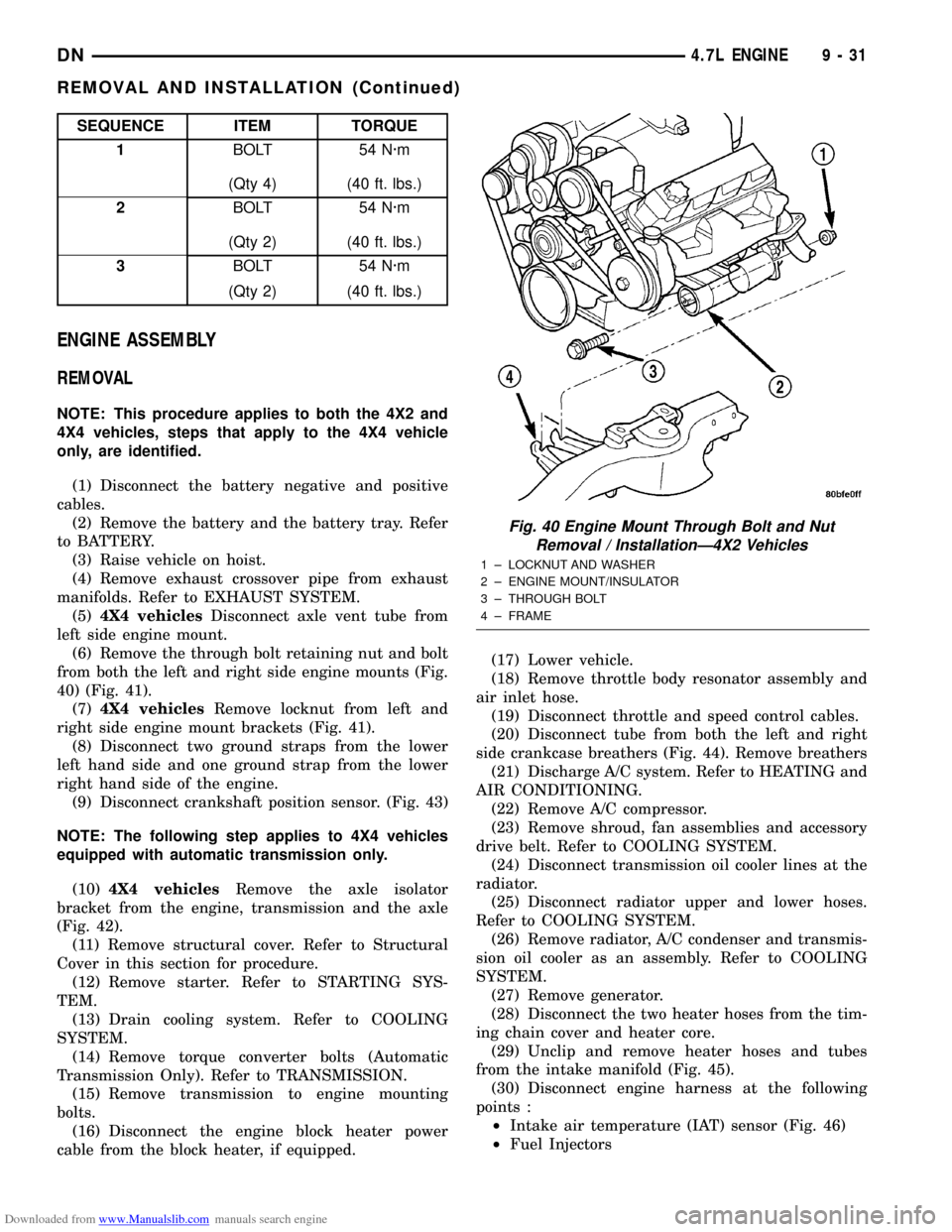
(6) Remove the through bolt retaining nut and bolt
from both the left and right side engine mounts (Fig.
40) (Fig. 41).
(7)4X4 vehiclesRemove locknut from left and
right side engine mount brackets (Fig. 41).
(8) Disconnect two ground straps from the lower
left hand side and one ground strap from the lower
right hand side of the engine.
(9) Disconnect crankshaft position sensor. (Fig. 43)
NOTE: The following step applies to 4X4 vehicles
equipped with automatic transmission only.
(10)4X4 vehiclesRemove the axle isolator
bracket from the engine, transmission and the axle
(Fig. 42).
(11) Remove structural cover. Refer to Structural
Cover in this section for procedure.
(12) Remove starter. Refer to STARTING SYS-
TEM.
(13) Drain cooling system. Refer to COOLING
SYSTEM.
(14) Remove torque converter bolts (Automatic
Transmission Only). Refer to TRANSMISSION.
(15) Remove transmission to engine mounting
bolts.
(16) Disconnect the engine block heater power
cable from the block heater, if equipped.(17) Lower vehicle.
(18) Remove throttle body resonator assembly and
air inlet hose.
(19) Disconnect throttle and speed control cables.
(20) Disconnect tube from both the left and right
side crankcase breathers (Fig. 44). Remove breathers
(21) Discharge A/C system. Refer to HEATING and
AIR CONDITIONING.
(22) Remove A/C compressor.
(23) Remove shroud, fan assemblies and accessory
drive belt. Refer to COOLING SYSTEM.
(24) Disconnect transmission oil cooler lines at the
radiator.
(25) Disconnect radiator upper and lower hoses.
Refer to COOLING SYSTEM.
(26) Remove radiator, A/C condenser and transmis-
sion oil cooler as an assembly. Refer to COOLING
SYSTEM.
(27) Remove generator.
(28) Disconnect the two heater hoses from the tim-
ing chain cover and heater core.
(29) Unclip and remove heater hoses and tubes
from the intake manifold (Fig. 45).
(30) Disconnect engine harness at the following
points :
²Intake air temperature (IAT) sensor (Fig. 46)
²Fuel Injectors
SEQUENCE ITEM TORQUE
1BOLT 54 N´m
(Qty 4) (40 ft. lbs.)
2BOLT 54 N´m
(Qty 2) (40 ft. lbs.)
3BOLT 54 N´m
(Qty 2) (40 ft. lbs.)
Fig. 40 Engine Mount Through Bolt and Nut
Removal / InstallationÐ4X2 Vehicles
1 ± LOCKNUT AND WASHER
2 ± ENGINE MOUNT/INSULATOR
3 ± THROUGH BOLT
4 ± FRAME
DN4.7L ENGINE 9 - 31
REMOVAL AND INSTALLATION (Continued)
Page 103 of 193

Downloaded from www.Manualslib.com manuals search engine (9) Disconnect the accelerator linkage.
(10) Remove throttle body.
(11) Perform the Fuel System Pressure release
procedure (refer to Group 14, fuel System).
(12) Disconnect the fuel supply line.
(13) Disconnect the starter wires.
(14) Disconnect the oil pressure sending unit wire.
(15) Discharge the air conditioning system, if
equipped (refer to Group 24, Heating and Air Condi-
tioning for service procedures).
(16) Disconnect the air conditioning hoses.
(17) Disconnect the power steering hoses, if
equipped.
(18) Remove starter motor (refer to Group 8B, Bat-
tery/Starter/Generator Service).
(19) Remove the generator (refer to Group 8B, Bat-
tery/Starter/Generator Service).
(20) Raise and support the vehicle on a hoist.
(21) Disconnect exhaust pipe at manifold.
(22) Refer to Group 21, Transmissions for trans-
mission removal.
CAUTION: DO NOT lift the engine by the intake
manifold.
(23) Install an engine lifting fixture.
(24) The engine and front driving axle (engine/ax-
le/transmission) are connected through insulators
and support brackets. Separate the engine as follows:
²LEFT SIDEÐRemove 2 bolts attaching
(engine/pinion nose/transmission) bracket to trans-
mission bell housing. Remove 2 bracket to pinion
nose adaptor bolts. Separate engine from insulator by
removing upper nut washer assembly and bolt from
engine support bracket.
²RIGHT SIDEÐRemove 2 bracket to axle (dis-
connect housing) bolts and a bracket to bell housing
bolt. Separate engine from insulator by removing
upper nut washer assembly and bolt from engine
support bracket.
(25) Lower the vehicle.
(26) Install engine assembly on engine repair
stand.
INSTALLATION
(1) Remove engine from the repair stand and posi-
tion in the engine compartment.
(2) Install an engine support fixture.
(3) Raise and support the vehicle on a hoist.
(4) Install the engine front mounts.
(5) Refer to Group, 21 Transmissions for transmis-
sion installation
(6) Install the inspection plate.
(7) Remove transmission support.
(8) Install exhaust pipe to manifold.
(9) Lower the vehicle.
(10) Remove engine lifting fixture.(11) Install the generator (refer to Group 8B, Bat-
tery/Starter/Generator Service).
(12) Install starter motor (refer to Group 8B, Bat-
tery/Starter/Generator Service).
(13) Connect power steering hoses, if equipped.
(14) Connect air conditioning hoses.
(15) Evacuate and charge the air conditioning sys-
tem, if equipped (refer to Group 24, Heater and Air
Conditioning for service procedures).
(16) Using a new gasket, install throttle body.
Tighten the throttle body bolts to 23 N´m (200 in.
lbs.) torque.
(17) Connect the accelerator linkage.
(18) Connect the starter wires.
(19) Connect the oil pressure sending unit wire.
(20) Install the distributor cap and wiring.
(21) Connect the vacuum supply lines to the
intake manifold.
(22) Connect the fuel supply lines.
(23) Install the radiator (refer to Group 7, Cooling
System). Connect the radiator hoses and heater
hoses.
(24) Install fan shroud in position.
(25) Fill cooling system (refer to Group 7, Cooling
System for the proper procedure).
(26) Install the air cleaner.
(27) Install the battery.
(28) Warm engine and adjust.
(29) Install hood and line up with the scribe
marks.
(30) Road test vehicle.
INTAKE MANIFOLD
REMOVAL
(1) Disconnect the battery negative cable.
(2) Drain the cooling system. Refer to COOLING
SYSTEM.
(3) Remove the A/C compressor. Refer to HEAT-
ING and AIR CONDITIONING.
(4) Remove the generator. Refer to CHARGING
SYSTEM.
(5) Remove the accessory drive bracket.
(6) Remove the air cleaner assembly and air inlet
hose.
(7) Perform the fuel pressure release procedure.
Refer to FUEL SYSTEM.
(8) Disconnect the fuel supply line from the fuel
rail. Refer to FUEL SYSTEM.
(9) Disconnect the accelerator linkage and, if so
equipped, the speed control and transmission kick-
down cables.
(10) Remove the distributor cap and wires.
(11) Disconnect the coil wires.
(12) Disconnect the coolant temperature sending
unit wire.
DN5.2L ENGINE 9 - 103
REMOVAL AND INSTALLATION (Continued)
Page 163 of 193

Downloaded from www.Manualslib.com manuals search engine (15) Discharge the air conditioning system, if
equipped. Refer to HEATING and AIR CONDITION-
ING.
(16) Disconnect the air conditioning hoses.
(17) Disconnect the power steering hoses, if
equipped.
(18) Remove starter motor. Refer to STARTING
SYSTEMS.
(19) Remove the generator.
(20) Raise and support the vehicle on a hoist.
(21) Disconnect exhaust pipe at manifold.
(22) Remove Transmission. Refer to TRANSMIS-
SIONS.
CAUTION: DO NOT lift the engine by the intake
manifold.
(23) Install an engine lifting fixture.
(24)2WD VEHICLESÐRemove engine front
mount bolts.
(25)4WD VEHICLESÐThe engine and front
driving axle (engine/axle/transmission) are connectedthrough insulators and support brackets. Separate
the engine as follows:
²LEFT SIDEÐRemove 2 bolts attaching
(engine/pinion nose/transmission) bracket to trans-
mission bell housing. Remove 2 bracket to pinion
nose adaptor bolts. Separate engine from insulator by
removing upper nut washer assembly and bolt from
engine support bracket.
²RIGHT SIDEÐRemove 2 bracket to axle (dis-
connect housing) bolts and a bracket to bell housing
bolt. Separate engine from insulator by removing
upper nut washer assembly and bolt from engine
support bracket.
(26) Lower the vehicle.
(27) Install engine assembly on engine repair
stand.
INSTALLATION
(1) Remove engine from the repair stand and posi-
tion in the engine compartment.
(2) Install an engine support fixture.
(3) Raise and support the vehicle on a hoist.
(4) Install the engine front mounts.
(5) Refer to Group, 21 Transmissions for transmis-
sion installation
(6) Install the inspection plate.
(7) Remove transmission support.
(8) Install exhaust pipe to manifold.
(9) Lower the vehicle.
(10) Remove engine lifting fixture.
(11) Install the generator.
(12) Install starter motor.
(13) Connect power steering hoses, if equipped.
(14) Connect air conditioning hoses.
(15) Evacuate and charge the air conditioning sys-
tem, if equipped.
(16) Using a new gasket, install throttle body.
Tighten the throttle body bolts to 23 N´m (200 in.
lbs.) torque.
(17) Connect the accelerator linkage.
(18) Connect the starter wires.
(19) Connect the oil pressure wire.
(20) Install the distributor cap and wiring.
(21) Connect the vacuum lines.
(22) Connect the fuel lines.
(23) Install the radiator. Connect the radiator
hoses and heater hoses.
(24) Install fan shroud in position.
(25) Fill cooling system.
(26) Install the air cleaner assembly and air inlet
hose.
(27) Install the battery.
(28) Warm engine and adjust.
(29) Install hood and line up with the scribe
marks.
(30) Road test vehicle.
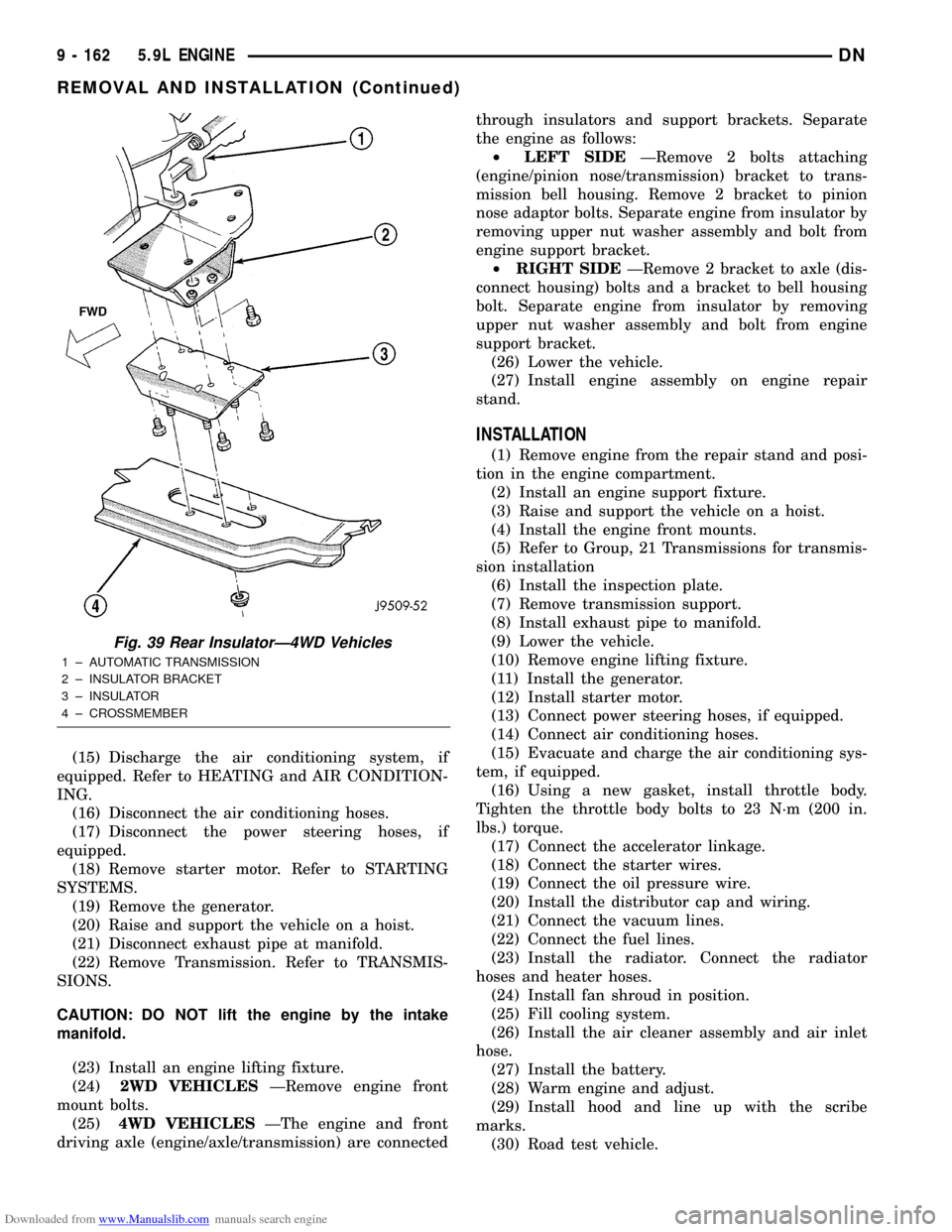
Fig. 39 Rear InsulatorÐ4WD Vehicles
1 ± AUTOMATIC TRANSMISSION
2 ± INSULATOR BRACKET
3 ± INSULATOR
4 ± CROSSMEMBER
9 - 162 5.9L ENGINEDN
REMOVAL AND INSTALLATION (Continued)