timing belt DODGE DURANGO 1998 1.G Workshop Manual
[x] Cancel search | Manufacturer: DODGE, Model Year: 1998, Model line: DURANGO, Model: DODGE DURANGO 1998 1.GPages: 193, PDF Size: 5.65 MB
Page 11 of 193
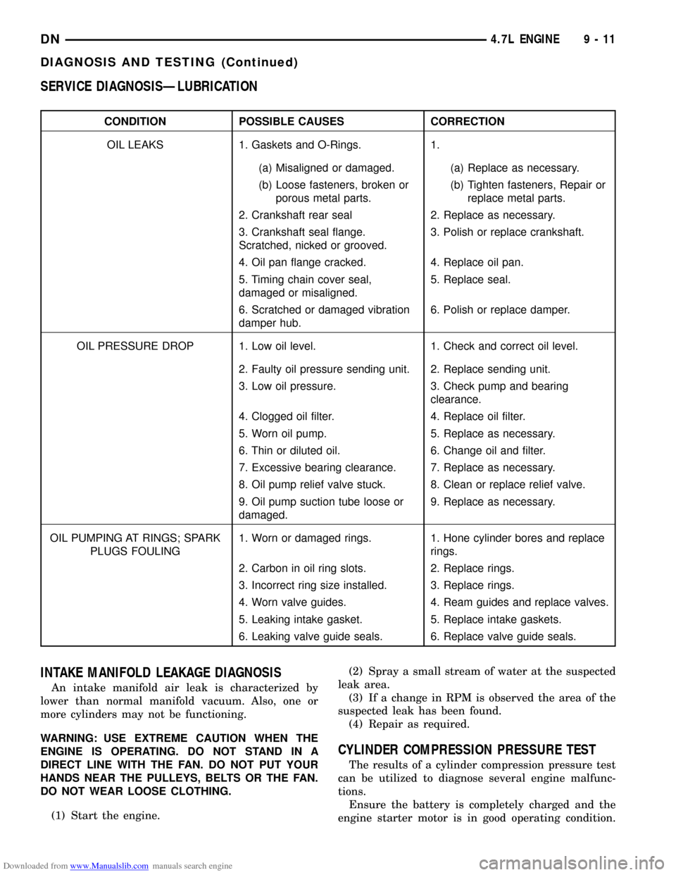
Downloaded from www.Manualslib.com manuals search engine SERVICE DIAGNOSISÐLUBRICATION
CONDITION POSSIBLE CAUSES CORRECTION
OIL LEAKS 1. Gaskets and O-Rings. 1.
(a) Misaligned or damaged. (a) Replace as necessary.
(b) Loose fasteners, broken or
porous metal parts.(b) Tighten fasteners, Repair or
replace metal parts.
2. Crankshaft rear seal 2. Replace as necessary.
3. Crankshaft seal flange.
Scratched, nicked or grooved.3. Polish or replace crankshaft.
4. Oil pan flange cracked. 4. Replace oil pan.
5. Timing chain cover seal,
damaged or misaligned.5. Replace seal.
6. Scratched or damaged vibration
damper hub.6. Polish or replace damper.
OIL PRESSURE DROP 1. Low oil level. 1. Check and correct oil level.
2. Faulty oil pressure sending unit. 2. Replace sending unit.
3. Low oil pressure. 3. Check pump and bearing
clearance.
4. Clogged oil filter. 4. Replace oil filter.
5. Worn oil pump. 5. Replace as necessary.
6. Thin or diluted oil. 6. Change oil and filter.
7. Excessive bearing clearance. 7. Replace as necessary.
8. Oil pump relief valve stuck. 8. Clean or replace relief valve.
9. Oil pump suction tube loose or
damaged.9. Replace as necessary.
OIL PUMPING AT RINGS; SPARK
PLUGS FOULING1. Worn or damaged rings. 1. Hone cylinder bores and replace
rings.
2. Carbon in oil ring slots. 2. Replace rings.
3. Incorrect ring size installed. 3. Replace rings.
4. Worn valve guides. 4. Ream guides and replace valves.
5. Leaking intake gasket. 5. Replace intake gaskets.
6. Leaking valve guide seals. 6. Replace valve guide seals.
INTAKE MANIFOLD LEAKAGE DIAGNOSIS
An intake manifold air leak is characterized by
lower than normal manifold vacuum. Also, one or
more cylinders may not be functioning.
WARNING: USE EXTREME CAUTION WHEN THE
ENGINE IS OPERATING. DO NOT STAND IN A
DIRECT LINE WITH THE FAN. DO NOT PUT YOUR
HANDS NEAR THE PULLEYS, BELTS OR THE FAN.
DO NOT WEAR LOOSE CLOTHING.
(1) Start the engine.(2) Spray a small stream of water at the suspected
leak area.
(3) If a change in RPM is observed the area of the
suspected leak has been found.
(4) Repair as required.
CYLINDER COMPRESSION PRESSURE TEST
The results of a cylinder compression pressure test
can be utilized to diagnose several engine malfunc-
tions.
Ensure the battery is completely charged and the
engine starter motor is in good operating condition.
DN4.7L ENGINE 9 - 11
DIAGNOSIS AND TESTING (Continued)
Page 41 of 193
Downloaded from www.Manualslib.com manuals search engine (4) For rocker arm installation on cylinders 1 and
7 Rotate the crankshaft until cylinder #2 is at TDC
compression stroke.
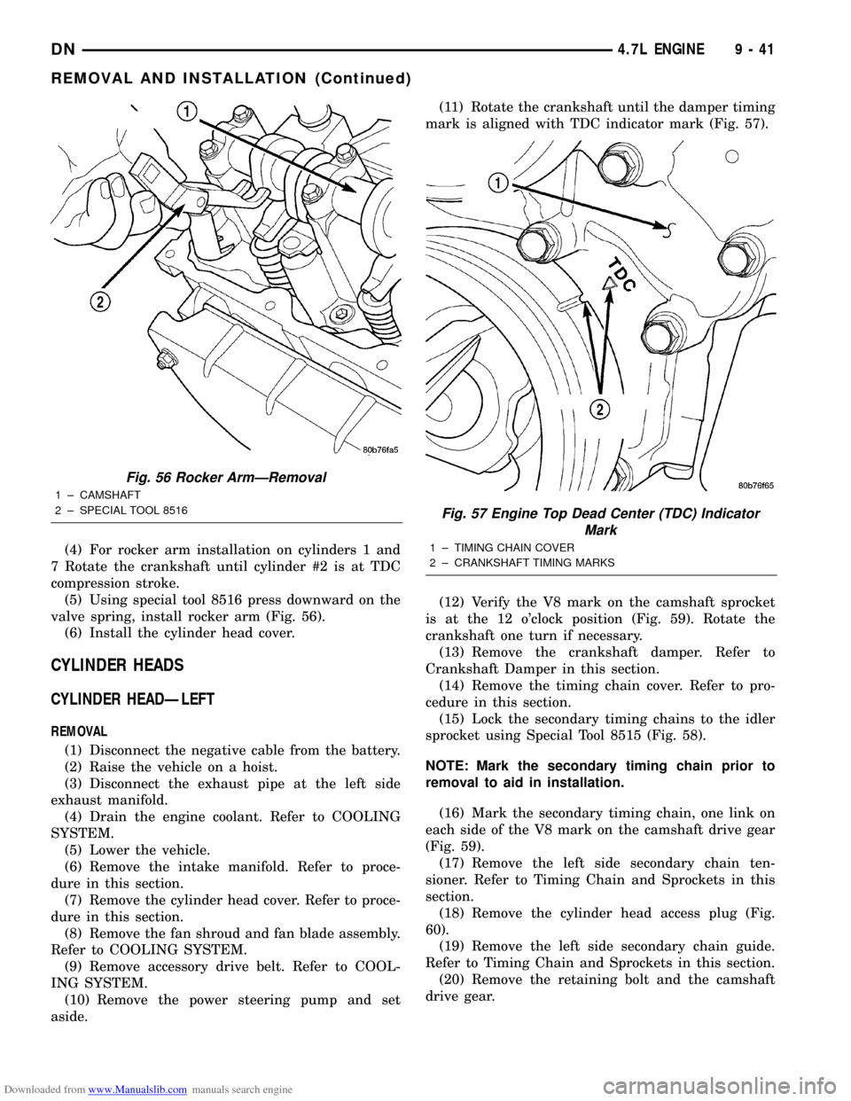
(5) Using special tool 8516 press downward on the
valve spring, install rocker arm (Fig. 56).
(6) Install the cylinder head cover.
CYLINDER HEADS
CYLINDER HEADÐLEFT
REMOVAL
(1) Disconnect the negative cable from the battery.
(2) Raise the vehicle on a hoist.
(3) Disconnect the exhaust pipe at the left side
exhaust manifold.
(4) Drain the engine coolant. Refer to COOLING
SYSTEM.
(5) Lower the vehicle.
(6) Remove the intake manifold. Refer to proce-
dure in this section.
(7) Remove the cylinder head cover. Refer to proce-
dure in this section.
(8) Remove the fan shroud and fan blade assembly.
Refer to COOLING SYSTEM.
(9) Remove accessory drive belt. Refer to COOL-
ING SYSTEM.
(10) Remove the power steering pump and set
aside.(11) Rotate the crankshaft until the damper timing
mark is aligned with TDC indicator mark (Fig. 57).
(12) Verify the V8 mark on the camshaft sprocket
is at the 12 o'clock position (Fig. 59). Rotate the
crankshaft one turn if necessary.
(13) Remove the crankshaft damper. Refer to
Crankshaft Damper in this section.
(14) Remove the timing chain cover. Refer to pro-
cedure in this section.
(15) Lock the secondary timing chains to the idler
sprocket using Special Tool 8515 (Fig. 58).
NOTE: Mark the secondary timing chain prior to
removal to aid in installation.
(16) Mark the secondary timing chain, one link on
each side of the V8 mark on the camshaft drive gear
(Fig. 59).
(17) Remove the left side secondary chain ten-
sioner. Refer to Timing Chain and Sprockets in this
section.
(18) Remove the cylinder head access plug (Fig.
60).
(19) Remove the left side secondary chain guide.
Refer to Timing Chain and Sprockets in this section.
(20) Remove the retaining bolt and the camshaft
drive gear.
Fig. 56 Rocker ArmÐRemoval
1 ± CAMSHAFT
2 ± SPECIAL TOOL 8516
Fig. 57 Engine Top Dead Center (TDC) Indicator
Mark
1 ± TIMING CHAIN COVER
2 ± CRANKSHAFT TIMING MARKS
DN4.7L ENGINE 9 - 41
REMOVAL AND INSTALLATION (Continued)
Page 44 of 193
Downloaded from www.Manualslib.com manuals search engine (14) Install the crankshaft damper. Tighten
damper bolt 175 N´m (130 Ft. Lbs.).
(15) Install the power steering pump.
(16) Install the fan blade assembly and fan
shroud.
(17) Install the cylinder head cover.
(18) Install the intake manifold.
(19) Refill the cooling system
(20) Raise the vehicle.
(21) Install the exhaust pipe onto the left exhaust
manifold.
(22) Lower the vehicle.
(23) Connect the negative cable to the battery.
(24) Start the engine and check for leaks.
CYLINDER HEADÐRIGHT
REMOVAL
(1) Disconnect battery negitive cable.
(2) Raise the vehicle on a hoist.
(3) Disconnect the exhaust pipe at the right side
exhaust manifold.
(4) Drain the engine coolant. Refer to COOLING
SYSTEM.
(5) Lower the vehicle.
(6) Remove the intake manifold. Refer to proce-
dure in this section.
(7) Remove the cylinder head cover. Refer to proce-
dure in this section.
(8) Remove the fan shroud. Refer to COOLING
SYSTEM.
(9) Remove oil fill housing from cylinder head.
(10) Remove accessory drive belt. Refer to COOL-
ING SYSTEM.
(11) Rotate the crankshaft until the damper timing
mark is aligned with TDC indicator mark (Fig. 57).
(12) Verify the V8 mark on the camshaft sprocket
is at the 12 o'clock position (Fig. 59). Rotate the
crankshaft one turn if necessary.
(13) Remove the crankshaft damper. Refer to
Crankshaft Damper in this section.(14) Remove the timing chain cover. Refer to Tim-
ing Chain Cover in this section.
(15) Lock the secondary timing chains to the idler
sprocket using Special Tool 8515 (Fig. 58).
NOTE: Mark the secondary timing chain prior to
removal to aid in installation.
(16) Mark the secondary timing chain, one link on
each side of the V8 mark on the camshaft drive gear
(Fig. 59).
(17) Remove the right side secondary chain ten-
sioner. Refer to Timing Chain and Sprockets in this
section.
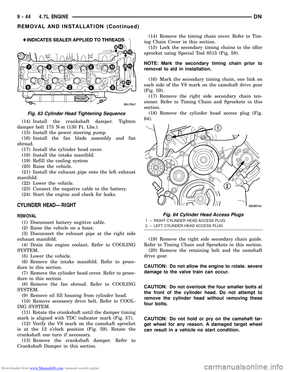
(18) Remove the cylinder head access plug (Fig.
64).
(19) Remove the right side secondary chain guide.
Refer to Timing Chain and Sprockets in this section.
(20) Remove the retaining bolt and the camshaft
drive gear.
CAUTION: Do not allow the engine to rotate. severe
damage to the valve train can occur.
CAUTION: Do not overlook the four smaller bolts at
the front of the cylinder head. Do not attempt to
remove the cylinder head without removing these
four bolts.
CAUTION: Do not hold or pry on the camshaft tar-
get wheel for any reason. A damaged target wheel
can result in a vehicle no start condition.
Fig. 63 Cylinder Head Tightening Sequence
Fig. 64 Cylinder Head Access Plugs
1 ± RIGHT CYLINDER HEAD ACCESS PLUG
2 ± LEFT CYLINDER HEAD ACCESS PLUG
9 - 44 4.7L ENGINEDN
REMOVAL AND INSTALLATION (Continued)
Page 48 of 193
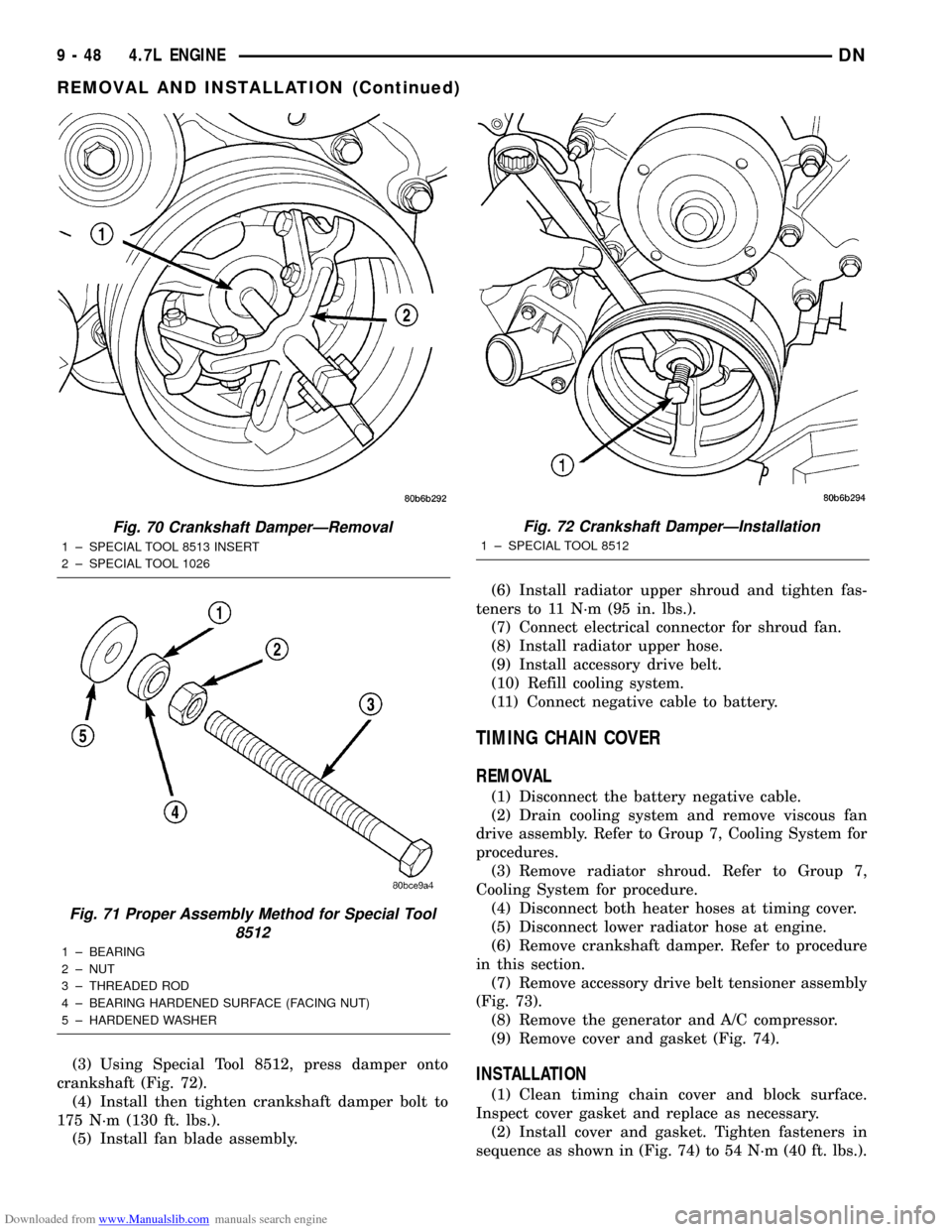
Downloaded from www.Manualslib.com manuals search engine (3) Using Special Tool 8512, press damper onto
crankshaft (Fig. 72).
(4) Install then tighten crankshaft damper bolt to
175 N´m (130 ft. lbs.).
(5) Install fan blade assembly.(6) Install radiator upper shroud and tighten fas-
teners to 11 N´m (95 in. lbs.).
(7) Connect electrical connector for shroud fan.
(8) Install radiator upper hose.
(9) Install accessory drive belt.
(10) Refill cooling system.
(11) Connect negative cable to battery.
TIMING CHAIN COVER
REMOVAL
(1) Disconnect the battery negative cable.
(2) Drain cooling system and remove viscous fan
drive assembly. Refer to Group 7, Cooling System for
procedures.
(3) Remove radiator shroud. Refer to Group 7,
Cooling System for procedure.
(4) Disconnect both heater hoses at timing cover.
(5) Disconnect lower radiator hose at engine.
(6) Remove crankshaft damper. Refer to procedure
in this section.
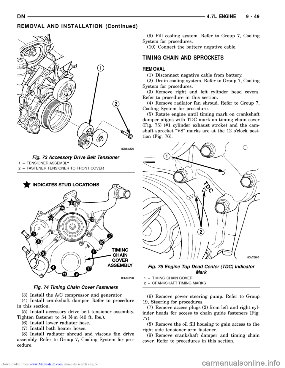
(7) Remove accessory drive belt tensioner assembly
(Fig. 73).
(8) Remove the generator and A/C compressor.
(9) Remove cover and gasket (Fig. 74).
INSTALLATION
(1) Clean timing chain cover and block surface.
Inspect cover gasket and replace as necessary.
(2) Install cover and gasket. Tighten fasteners in
sequence as shown in (Fig. 74) to 54 N´m (40 ft. lbs.).
Fig. 70 Crankshaft DamperÐRemoval
1 ± SPECIAL TOOL 8513 INSERT
2 ± SPECIAL TOOL 1026
Fig. 71 Proper Assembly Method for Special Tool
8512
1 ± BEARING
2 ± NUT
3 ± THREADED ROD
4 ± BEARING HARDENED SURFACE (FACING NUT)
5 ± HARDENED WASHER
Fig. 72 Crankshaft DamperÐInstallation
1 ± SPECIAL TOOL 8512
9 - 48 4.7L ENGINEDN
REMOVAL AND INSTALLATION (Continued)
Page 49 of 193
Downloaded from www.Manualslib.com manuals search engine (3) Install the A/C compressor and generator.
(4) Install crankshaft damper. Refer to procedure
in this section.
(5) Install accessory drive belt tensioner assembly.
Tighten fastener to 54 N´m (40 ft. lbs.).
(6) Install lower radiator hose.
(7) Install both heater hoses.
(8) Install radiator shroud and viscous fan drive
assembly. Refer to Group 7, Cooling System for pro-
cedure.(9) Fill cooling system. Refer to Group 7, Cooling
System for procedures.
(10) Connect the battery negative cable.
TIMING CHAIN AND SPROCKETS
REMOVAL
(1) Disconnect negative cable from battery.
(2) Drain cooling system. Refer to Group 7, Cooling
System for procedures.
(3) Remove right and left cylinder head covers.
Refer to procedure in this section.
(4) Remove radiator fan shroud. Refer to Group 7,
Cooling System for procedure.
(5) Rotate engine until timing mark on crankshaft
damper aligns with TDC mark on timing chain cover
(Fig. 75) (#1 cylinder exhaust stroke) and the cam-
shaft sprocket ªV8º marks are at the 12 o'clock posi-
tion (Fig. 76).
(6) Remove power steering pump. Refer to Group
19, Steering for procedures.
(7) Remove access plugs (2) from left and right cyl-
inder heads for access to chain guide fasteners (Fig.
77).
(8) Remove the oil fill housing to gain access to the
right side tensioner arm fastener.
(9) Remove crankshaft damper and timing chain
cover. Refer to procedures in this section.
Fig. 73 Accessory Drive Belt Tensioner
1 ± TENSIONER ASSEMBLY
2 ± FASTENER TENSIONER TO FRONT COVER
Fig. 74 Timing Chain Cover Fasteners
Fig. 75 Engine Top Dead Center (TDC) Indicator
Mark
1 ± TIMING CHAIN COVER
2 ± CRANKSHAFT TIMING MARKS
DN4.7L ENGINE 9 - 49
REMOVAL AND INSTALLATION (Continued)
Page 71 of 193
Downloaded from www.Manualslib.com manuals search engine (2) Remove accessory drive belt refer to Group 7,
Cooling System for procedure.
(3) Remove A/C compressor mouning fasteners and
set aside.(4) Drain cooling system. Refer to Group 7, Cooling
System for procedure.
(5) Remove upper radiator hose.
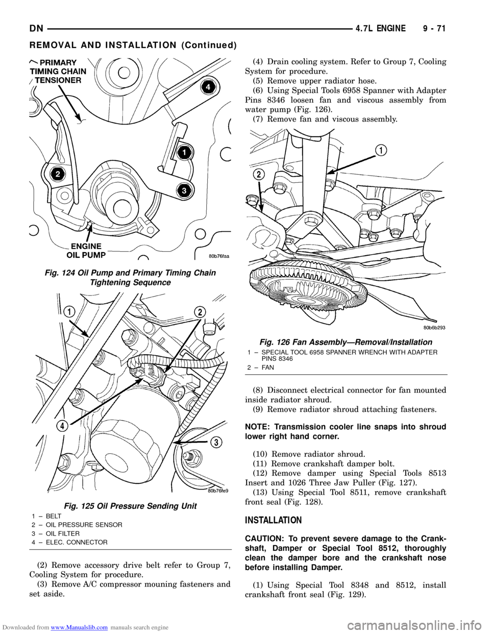
(6) Using Special Tools 6958 Spanner with Adapter
Pins 8346 loosen fan and viscous assembly from
water pump (Fig. 126).
(7) Remove fan and viscous assembly.
(8) Disconnect electrical connector for fan mounted
inside radiator shroud.
(9) Remove radiator shroud attaching fasteners.
NOTE: Transmission cooler line snaps into shroud
lower right hand corner.
(10) Remove radiator shroud.
(11) Remove crankshaft damper bolt.
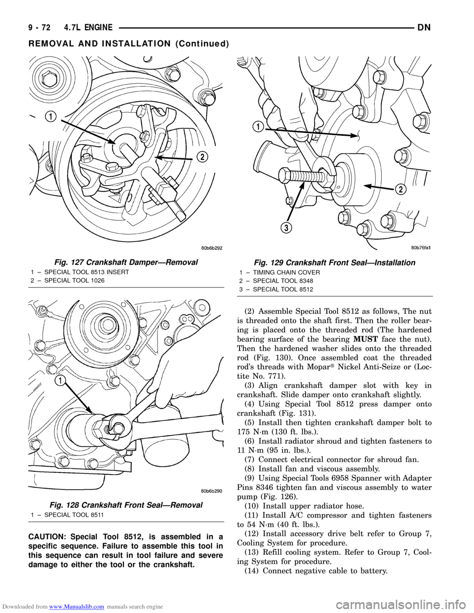
(12) Remove damper using Special Tools 8513
Insert and 1026 Three Jaw Puller (Fig. 127).
(13) Using Special Tool 8511, remove crankshaft
front seal (Fig. 128).
INSTALLATION
CAUTION: To prevent severe damage to the Crank-
shaft, Damper or Special Tool 8512, thoroughly
clean the damper bore and the crankshaft nose
before installing Damper.
(1) Using Special Tool 8348 and 8512, install
crankshaft front seal (Fig. 129).
Fig. 124 Oil Pump and Primary Timing Chain
Tightening Sequence
Fig. 125 Oil Pressure Sending Unit
1 ± BELT
2 ± OIL PRESSURE SENSOR
3 ± OIL FILTER
4 ± ELEC. CONNECTOR
Fig. 126 Fan AssemblyÐRemoval/Installation
1 ± SPECIAL TOOL 6958 SPANNER WRENCH WITH ADAPTER
PINS 8346
2±FAN
DN4.7L ENGINE 9 - 71
REMOVAL AND INSTALLATION (Continued)
Page 72 of 193
Downloaded from www.Manualslib.com manuals search engine CAUTION: Special Tool 8512, is assembled in a
specific sequence. Failure to assemble this tool in
this sequence can result in tool failure and severe
damage to either the tool or the crankshaft.(2) Assemble Special Tool 8512 as follows, The nut
is threaded onto the shaft first. Then the roller bear-
ing is placed onto the threaded rod (The hardened
bearing surface of the bearingMUSTface the nut).
Then the hardened washer slides onto the threaded
rod (Fig. 130). Once assembled coat the threaded
rod's threads with MopartNickel Anti-Seize or (Loc-
tite No. 771).
(3) Align crankshaft damper slot with key in
crankshaft. Slide damper onto crankshaft slightly.
(4) Using Special Tool 8512 press damper onto
crankshaft (Fig. 131).
(5) Install then tighten crankshaft damper bolt to
175 N´m (130 ft. lbs.).
(6) Install radiator shroud and tighten fasteners to
11 N´m (95 in. lbs.).
(7) Connect electrical connector for shroud fan.
(8) Install fan and viscous assembly.
(9) Using Special Tools 6958 Spanner with Adapter
Pins 8346 tighten fan and viscous assembly to water
pump (Fig. 126).
(10) Install upper radiator hose.
(11) Install A/C compressor and tighten fasteners
to 54 N´m (40 ft. lbs.).
(12) Install accessory drive belt refer to Group 7,
Cooling System for procedure.
(13) Refill cooling system. Refer to Group 7, Cool-
ing System for procedure.
(14) Connect negative cable to battery.
Fig. 127 Crankshaft DamperÐRemoval
1 ± SPECIAL TOOL 8513 INSERT
2 ± SPECIAL TOOL 1026
Fig. 128 Crankshaft Front SealÐRemoval
1 ± SPECIAL TOOL 8511
Fig. 129 Crankshaft Front SealÐInstallation
1 ± TIMING CHAIN COVER
2 ± SPECIAL TOOL 8348
3 ± SPECIAL TOOL 8512
9 - 72 4.7L ENGINEDN
REMOVAL AND INSTALLATION (Continued)
Page 110 of 193
Downloaded from www.Manualslib.com manuals search engine (7) Position the fan shroud and install the bolts.
Tighten the retainer bolts to 11 N´m (95 in. lbs.)
torque.
(8) Connect the negative cable to the battery.
TIMING CHAIN COVER
(1) Disconnect the negative cable from the battery.
(2) Drain cooling system (refer to Group 7, Cooling
System).
(3) Remove the serpentine belt (refer to Group 7,
Cooling System).
(4) Remove water pump (refer to Group 7, Cooling
System).
(5) Remove power steering pump (refer to Group
19, Steering).
(6) Remove vibration damper.
(7) Remove fuel lines (refer to Group 14, Fuel Sys-
tem).
(8) Loosen oil pan bolts and remove the front bolt
at each side.
(9) Remove the cover bolts.
(10) Remove chain case cover and gasket using
extreme caution to avoid damaging oil pan gasket.
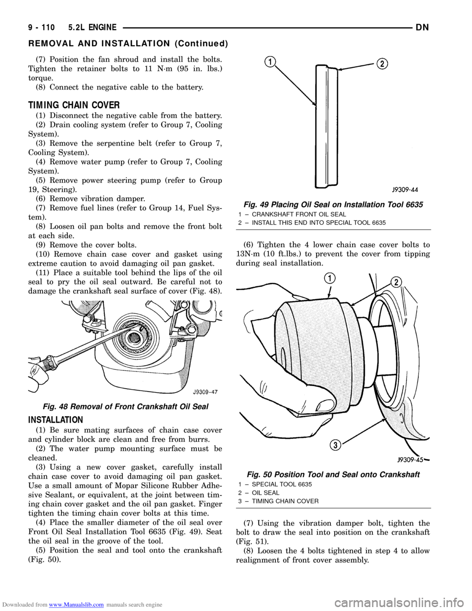
(11) Place a suitable tool behind the lips of the oil
seal to pry the oil seal outward. Be careful not to
damage the crankshaft seal surface of cover (Fig. 48).
INSTALLATION
(1) Be sure mating surfaces of chain case cover
and cylinder block are clean and free from burrs.
(2) The water pump mounting surface must be
cleaned.
(3) Using a new cover gasket, carefully install
chain case cover to avoid damaging oil pan gasket.
Use a small amount of Mopar Silicone Rubber Adhe-
sive Sealant, or equivalent, at the joint between tim-
ing chain cover gasket and the oil pan gasket. Finger
tighten the timing chain cover bolts at this time.
(4) Place the smaller diameter of the oil seal over
Front Oil Seal Installation Tool 6635 (Fig. 49). Seat
the oil seal in the groove of the tool.
(5) Position the seal and tool onto the crankshaft
(Fig. 50).(6) Tighten the 4 lower chain case cover bolts to
13N´m (10 ft.lbs.) to prevent the cover from tipping
during seal installation.
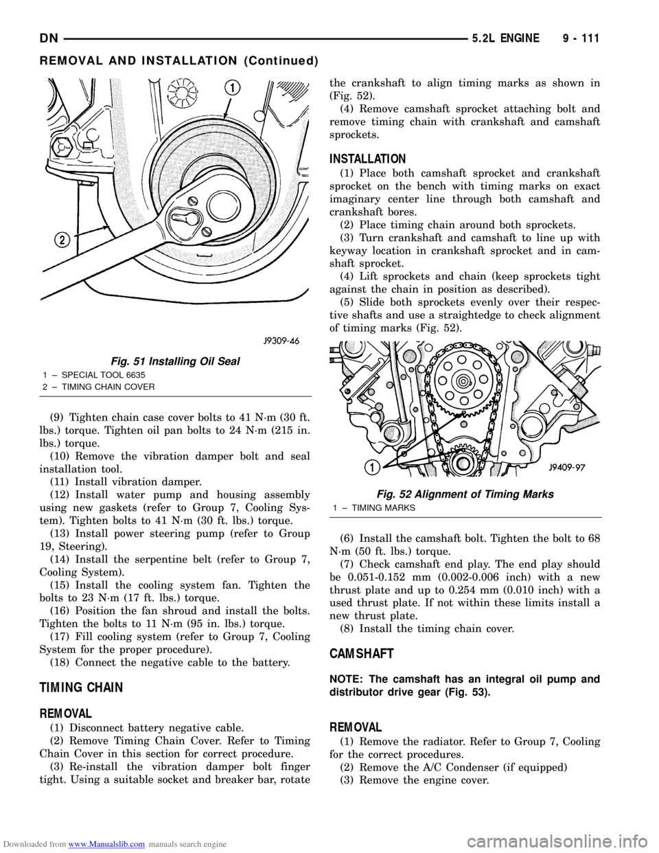
(7) Using the vibration damper bolt, tighten the
bolt to draw the seal into position on the crankshaft
(Fig. 51).
(8) Loosen the 4 bolts tightened in step 4 to allow
realignment of front cover assembly.
Fig. 48 Removal of Front Crankshaft Oil Seal
Fig. 49 Placing Oil Seal on Installation Tool 6635
1 ± CRANKSHAFT FRONT OIL SEAL
2 ± INSTALL THIS END INTO SPECIAL TOOL 6635
Fig. 50 Position Tool and Seal onto Crankshaft
1 ± SPECIAL TOOL 6635
2 ± OIL SEAL
3 ± TIMING CHAIN COVER
9 - 110 5.2L ENGINEDN
REMOVAL AND INSTALLATION (Continued)
Page 111 of 193
Downloaded from www.Manualslib.com manuals search engine (9) Tighten chain case cover bolts to 41 N´m (30 ft.
lbs.) torque. Tighten oil pan bolts to 24 N´m (215 in.
lbs.) torque.
(10) Remove the vibration damper bolt and seal
installation tool.
(11) Install vibration damper.
(12) Install water pump and housing assembly
using new gaskets (refer to Group 7, Cooling Sys-
tem). Tighten bolts to 41 N´m (30 ft. lbs.) torque.
(13) Install power steering pump (refer to Group
19, Steering).
(14) Install the serpentine belt (refer to Group 7,
Cooling System).
(15) Install the cooling system fan. Tighten the
bolts to 23 N´m (17 ft. lbs.) torque.
(16) Position the fan shroud and install the bolts.
Tighten the bolts to 11 N´m (95 in. lbs.) torque.
(17) Fill cooling system (refer to Group 7, Cooling
System for the proper procedure).
(18) Connect the negative cable to the battery.
TIMING CHAIN
REMOVAL
(1) Disconnect battery negative cable.
(2) Remove Timing Chain Cover. Refer to Timing
Chain Cover in this section for correct procedure.
(3) Re-install the vibration damper bolt finger
tight. Using a suitable socket and breaker bar, rotatethe crankshaft to align timing marks as shown in
(Fig. 52).
(4) Remove camshaft sprocket attaching bolt and
remove timing chain with crankshaft and camshaft
sprockets.
INSTALLATION
(1) Place both camshaft sprocket and crankshaft
sprocket on the bench with timing marks on exact
imaginary center line through both camshaft and
crankshaft bores.
(2) Place timing chain around both sprockets.
(3) Turn crankshaft and camshaft to line up with
keyway location in crankshaft sprocket and in cam-
shaft sprocket.
(4) Lift sprockets and chain (keep sprockets tight
against the chain in position as described).
(5) Slide both sprockets evenly over their respec-
tive shafts and use a straightedge to check alignment
of timing marks (Fig. 52).
(6) Install the camshaft bolt. Tighten the bolt to 68
N´m (50 ft. lbs.) torque.
(7) Check camshaft end play. The end play should
be 0.051-0.152 mm (0.002-0.006 inch) with a new
thrust plate and up to 0.254 mm (0.010 inch) with a
used thrust plate. If not within these limits install a
new thrust plate.
(8) Install the timing chain cover.
CAMSHAFT
NOTE: The camshaft has an integral oil pump and
distributor drive gear (Fig. 53).
REMOVAL
(1) Remove the radiator. Refer to Group 7, Cooling
for the correct procedures.
(2) Remove the A/C Condenser (if equipped)
(3) Remove the engine cover.
Fig. 51 Installing Oil Seal
1 ± SPECIAL TOOL 6635
2 ± TIMING CHAIN COVER
Fig. 52 Alignment of Timing Marks
1 ± TIMING MARKS
DN5.2L ENGINE 9 - 111
REMOVAL AND INSTALLATION (Continued)
Page 143 of 193
Downloaded from www.Manualslib.com manuals search engine SERVICE DIAGNOSISÐGASOLINE ENGINES
PERFORMANCE DIAGNOSIS CHARTÐGASOLINE ENGINES
CONDITION POSSIBLE CAUSES CORRECTION
ENGINE WILL
NOT CRANK1. Weak or dead battery 1. Charge/Replace Battery. Refer to Group 8A,
Battery, for correct procedures. Check charging
system. Refer to Group 8C, Charging Systems, for
correct procedures.
2. Corroded or loose battery
connections2. Clean/tighten suspect battery/starter connections
3. Faulty starter or related circuit(s) 3. Check starting system. Refer to Group 8B,
Starting Systems, for correct diagnostics/procedures
4. Seized accessory drive
component4. Remove accessory drive belt and attempt to start
engine. If engine starts, repair/replace seized
component.
5. Engine internal mechanical
failure or hydro-static lock5. Refer to Group 9, Engine, for correct diagnostics/
procedures
ENGINE CRANKS
BUT WILL NOT
START1. No spark 1. Check for spark. Refer to Group 8D, Ignition
System, for correct procedures.
2. No fuel 2. Perform fuel pressure test, and if necessary,
inspect fuel injector(s) and driver circuits. Refer to
Group 14, Fuel System, for correct procedures.
3. Low or no engine compression 3. Perform cylinder compression pressure test. Refer
to Group 9, Engine, for correct procedures.
ENGINE LOSS OF
POWER1. Worn or burned distributor rotor 1. Install new distributor rotor
2. Worn distributor shaft 2. Remove and repair distributor (Refer to Group 8D,
Ignition System
3. Worn or incorrect gapped spark
plugs3. Clean plugs and set gap. (Refer to Group 8D,
Ignition System)
4. Dirt or water in fuel system 4. Clean system and replace fuel filter
5. Faulty fuel pump 5. Install new fuel pump
6. Incorrect valve timing 6. Correct valve timing
7. Blown cylinder head gasket 7. Install new cylinder head gasket
8. Low compression 8. Test cylinder compression
9. Burned, warped, or pitted valves 9. Install/Reface valves as necessary
10. Plugged or restricted exhaust
system10. Install new parts as necessary
11. Faulty ignition cables 11. Replace any cracked or shorted cables
12. Faulty ignition coil 12. Test and replace, as necessary (Refer to Group
8D, Ignition System)
ENGINE STALLS
OR ROUGH IDLE1. Carbon build-up on throttle plate 1. Remove throttle body and de-carbon. (Refer to
Group 14 for correct procedures)
2. Engine idle speed too low 2. Check Idle Air Control circuit. (Refer to Group 14,
Fuel System)
9 - 142 5.9L ENGINEDN
DIAGNOSIS AND TESTING (Continued)