Can bus DODGE DURANGO 1999 1.G User Guide
[x] Cancel search | Manufacturer: DODGE, Model Year: 1999, Model line: DURANGO, Model: DODGE DURANGO 1999 1.GPages: 193, PDF Size: 5.65 MB
Page 151 of 193

Downloaded from www.Manualslib.com manuals search engine (2) Check intake manifold bolt torque.
(3) Perform cylinder compression test. Refer to
Cylinder Compression Pressure Test in the Engine
Diagnosis area of this section.
(4) Clean or replace spark plugs as necessary and
adjust gap as specified in Electrical Group 8D.
Tighten to specifications.
(5) Test resistance of spark plug cables. Refer to
Electrical Group 8D, Spark Plug Cables.
(6) Inspect the primary wires. Test coil output volt-
age and primary resistance. Replace parts as neces-
sary. Refer to Electrical Group 8D, for specifications.
(7) Test fuel pump for pressure. Refer to Group 14,
Fuel System Specifications.
(8) The air filter elements should be replaced as
specified in Lubrication and Maintenance, Group 0.
(9) Inspect crankcase ventilation system as out
lined in Group 0, Lubrication and Maintenance. For
emission controls see Group 25, Emission Controls
for service procedures.
(10) Road test vehicle as a final test.
ENGINE OIL
WARNING: NEW OR USED ENGINE OIL CAN BE
IRRITATING TO THE SKIN. AVOID PROLONGED OR
REPEATED SKIN CONTACT WITH ENGINE OIL.
CONTAMINANTS IN USED ENGINE OIL, CAUSED BY
INTERNAL COMBUSTION, CAN BE HAZARDOUS TO
YOUR HEALTH. THOROUGHLY WASH EXPOSED
SKIN WITH SOAP AND WATER. DO NOT WASH
SKIN WITH GASOLINE, DIESEL FUEL, THINNER, OR
SOLVENTS, HEALTH PROBLEMS CAN RESULT. DO
NOT POLLUTE, DISPOSE OF USED ENGINE OIL
PROPERLY.
ENGINE OIL SPECIFICATION
CAUTION: Do not use non-detergent or straight
mineral oil when adding or changing crankcase
lubricant. Engine failure can result.
API SERVICE GRADE CERTIFIED
In gasoline engines, use an engine oil that is API
Service Grade Certified (Fig. 12). Standard engine oil
identification notations have been adopted to aid in
the proper selection of engine oil. The identifying
notations are located on the label of engine oil plastic
bottles and the top of engine oil cans. MOPAR only
provides engine oil that conforms to this certification.
SAE VISCOSITY
An SAE viscosity grade is used to specify the vis-
cosity of engine oil. SAE 10W-30 specifies a multiple
viscosity engine oil. These are specified with a dualSAE viscosity grade which indicates the cold-to-hot
temperature viscosity range. When choosing an
engine oil, consider the range of temperatures the
vehicle will be operated in before the next oil change.
Select an engine oil that is best suited to your area's
particular ambient temperature range and variation
(Fig. 13).
ENERGY CONSERVING OIL
An Energy Conserving type oil is recommended for
gasoline engines. The designation of ENERGY CON-
SERVING is located on the label of an engine oil con-
tainer.
OIL LEVEL INDICATOR (DIPSTICK)
The engine oil level indicator is located at the right
front of the engine, left of the generator on 5.9L
engines (Fig. 14).
CRANKCASE OIL LEVEL INSPECTION
CAUTION: Do not overfill crankcase with engine oil,
oil foaming and oil pressure loss can result.
To ensure proper lubrication of an engine, the
engine oil must be maintained at an acceptable level.
The acceptable levels are indicated between the ADD
and SAFE marks on the engine oil dipstick.
(1) Position vehicle on level surface.
Fig. 12 Engine Oil Container Standard Notations
Fig. 13 Temperature/Engine Oil Viscosity
Recommendation
9 - 150 5.9L ENGINEDN
SERVICE PROCEDURES (Continued)
Page 174 of 193

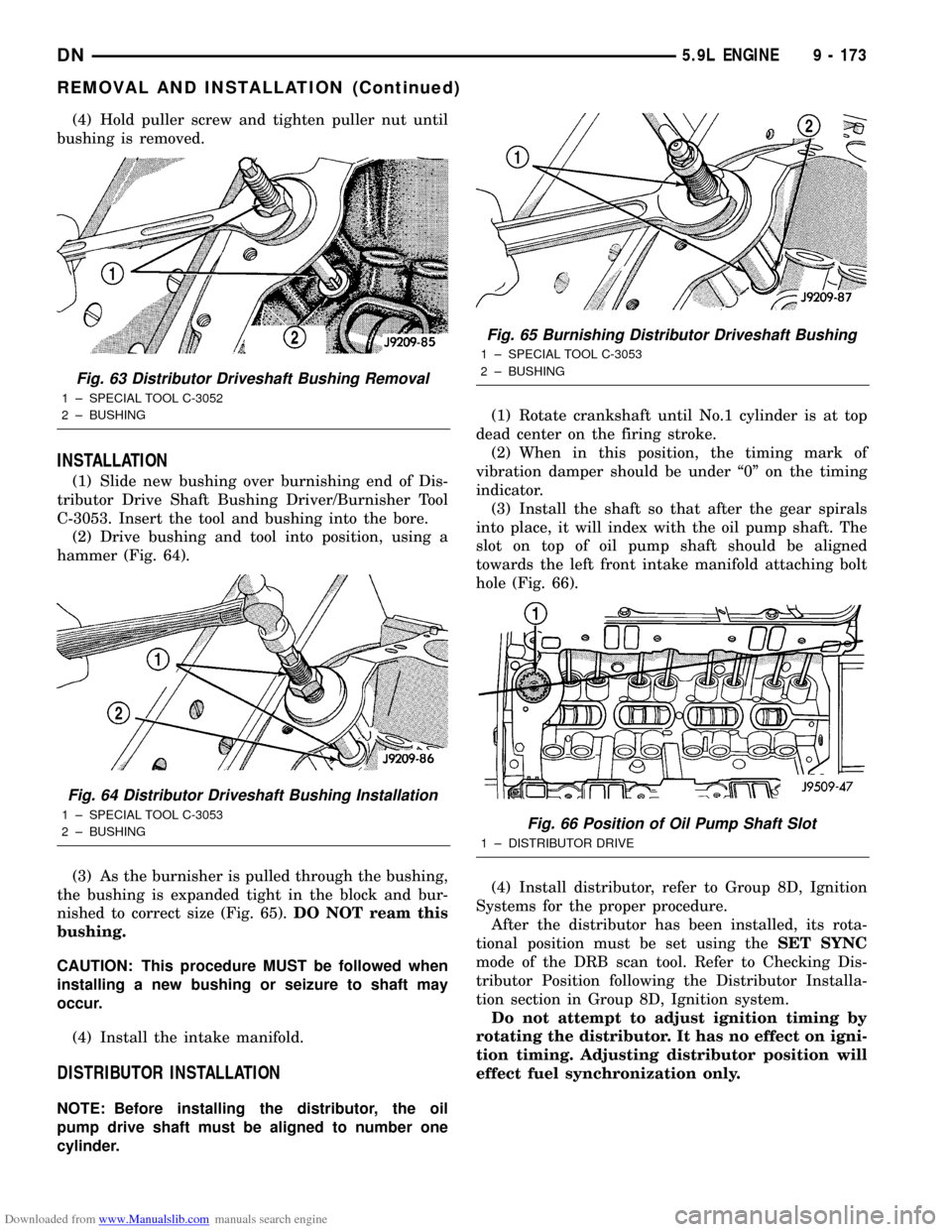
Downloaded from www.Manualslib.com manuals search engine (4) Hold puller screw and tighten puller nut until
bushing is removed.
INSTALLATION
(1) Slide new bushing over burnishing end of Dis-
tributor Drive Shaft Bushing Driver/Burnisher Tool
C-3053. Insert the tool and bushing into the bore.
(2) Drive bushing and tool into position, using a
hammer (Fig. 64).
(3) As the burnisher is pulled through the bushing,
the bushing is expanded tight in the block and bur-
nished to correct size (Fig. 65).DO NOT ream this
bushing.
CAUTION: This procedure MUST be followed when
installing a new bushing or seizure to shaft may
occur.
(4) Install the intake manifold.
DISTRIBUTOR INSTALLATION
NOTE: Before installing the distributor, the oil
pump drive shaft must be aligned to number one
cylinder.(1) Rotate crankshaft until No.1 cylinder is at top
dead center on the firing stroke.
(2) When in this position, the timing mark of
vibration damper should be under ª0º on the timing
indicator.
(3) Install the shaft so that after the gear spirals
into place, it will index with the oil pump shaft. The
slot on top of oil pump shaft should be aligned
towards the left front intake manifold attaching bolt
hole (Fig. 66).
(4) Install distributor, refer to Group 8D, Ignition
Systems for the proper procedure.
After the distributor has been installed, its rota-
tional position must be set using theSET SYNC
mode of the DRB scan tool. Refer to Checking Dis-
tributor Position following the Distributor Installa-
tion section in Group 8D, Ignition system.
Do not attempt to adjust ignition timing by
rotating the distributor. It has no effect on igni-
tion timing. Adjusting distributor position will
effect fuel synchronization only.
Fig. 63 Distributor Driveshaft Bushing Removal
1 ± SPECIAL TOOL C-3052
2 ± BUSHING
Fig. 64 Distributor Driveshaft Bushing Installation
1 ± SPECIAL TOOL C-3053
2 ± BUSHING
Fig. 65 Burnishing Distributor Driveshaft Bushing
1 ± SPECIAL TOOL C-3053
2 ± BUSHING
Fig. 66 Position of Oil Pump Shaft Slot
1 ± DISTRIBUTOR DRIVE
DN5.9L ENGINE 9 - 173
REMOVAL AND INSTALLATION (Continued)