Power DODGE DURANGO 1999 1.G User Guide
[x] Cancel search | Manufacturer: DODGE, Model Year: 1999, Model line: DURANGO, Model: DODGE DURANGO 1999 1.GPages: 193, PDF Size: 5.65 MB
Page 49 of 193
Downloaded from www.Manualslib.com manuals search engine (3) Install the A/C compressor and generator.
(4) Install crankshaft damper. Refer to procedure
in this section.
(5) Install accessory drive belt tensioner assembly.
Tighten fastener to 54 N´m (40 ft. lbs.).
(6) Install lower radiator hose.
(7) Install both heater hoses.
(8) Install radiator shroud and viscous fan drive
assembly. Refer to Group 7, Cooling System for pro-
cedure.(9) Fill cooling system. Refer to Group 7, Cooling
System for procedures.
(10) Connect the battery negative cable.
TIMING CHAIN AND SPROCKETS
REMOVAL
(1) Disconnect negative cable from battery.
(2) Drain cooling system. Refer to Group 7, Cooling
System for procedures.
(3) Remove right and left cylinder head covers.
Refer to procedure in this section.
(4) Remove radiator fan shroud. Refer to Group 7,
Cooling System for procedure.
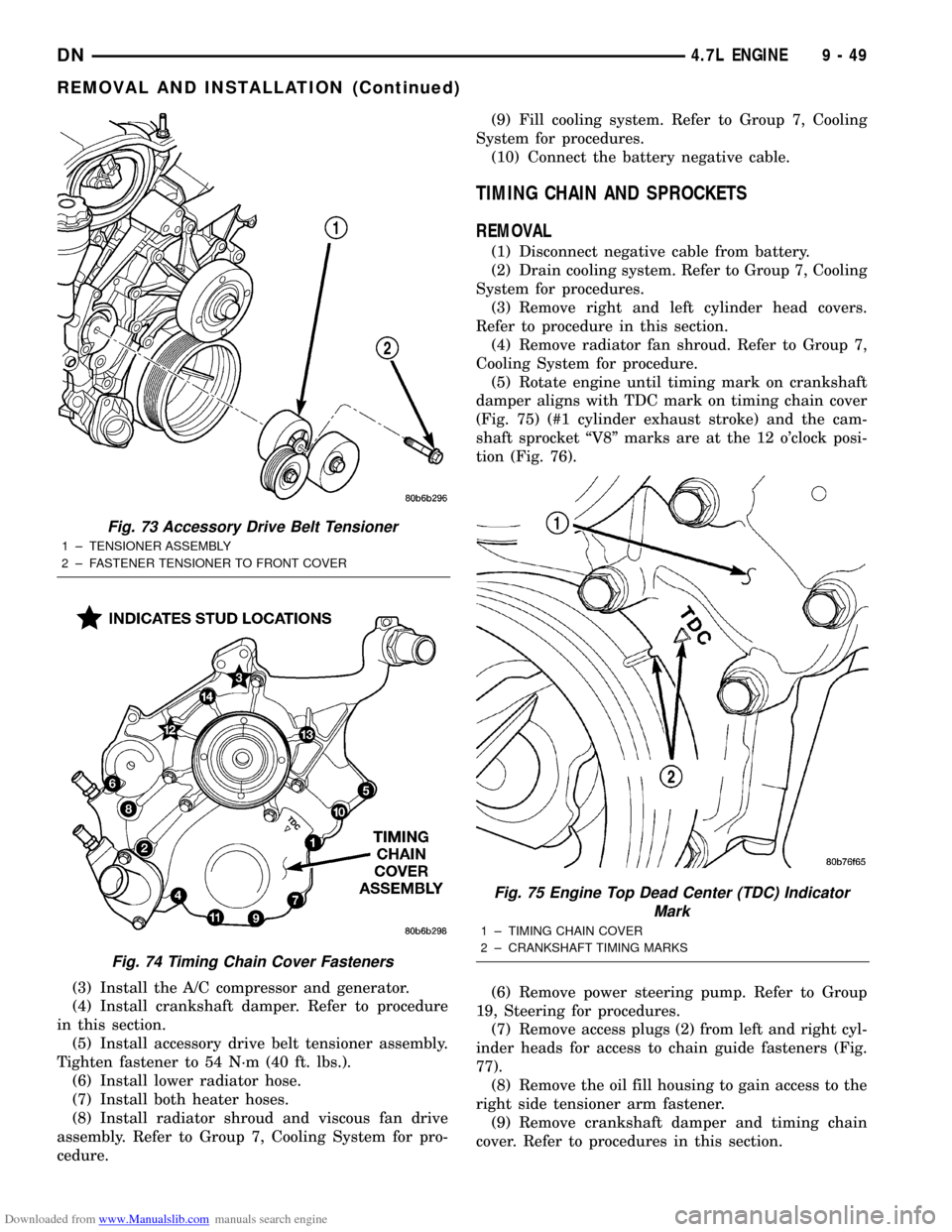
(5) Rotate engine until timing mark on crankshaft
damper aligns with TDC mark on timing chain cover
(Fig. 75) (#1 cylinder exhaust stroke) and the cam-
shaft sprocket ªV8º marks are at the 12 o'clock posi-
tion (Fig. 76).
(6) Remove power steering pump. Refer to Group
19, Steering for procedures.
(7) Remove access plugs (2) from left and right cyl-
inder heads for access to chain guide fasteners (Fig.
77).
(8) Remove the oil fill housing to gain access to the
right side tensioner arm fastener.
(9) Remove crankshaft damper and timing chain
cover. Refer to procedures in this section.
Fig. 73 Accessory Drive Belt Tensioner
1 ± TENSIONER ASSEMBLY
2 ± FASTENER TENSIONER TO FRONT COVER
Fig. 74 Timing Chain Cover Fasteners
Fig. 75 Engine Top Dead Center (TDC) Indicator
Mark
1 ± TIMING CHAIN COVER
2 ± CRANKSHAFT TIMING MARKS
DN4.7L ENGINE 9 - 49
REMOVAL AND INSTALLATION (Continued)
Page 55 of 193
Downloaded from www.Manualslib.com manuals search engine (24) Coat the large threaded access plug with
MopartThread Sealant with Teflon, then install
into the right cylinder head and tighten to 81 N´m
(60 ft. lbs.) (Fig. 77).(25) Install the oil fill housing.
(26) Install access plug in left cylinder head (Fig.
77).
(27) Install power steering pump. Refer to Group
19, Steering for procedure.
(28) Install radiator fan shroud. Refer to Group 7,
Cooling System for procedure.
(29) Fill cooling system. Refer to Group 7, Cooling
System for coolant fill procedure.
(30) Connect negative cable to battery.
IDLER SHAFTÐTIMING DRIVE
REMOVAL
(1) Remove the timing chain and sprockets. Refer
to procedure in this section.
NOTE: To remove the idler shaft, it is necessary to
tap threads into the shaft to install the removal tool.
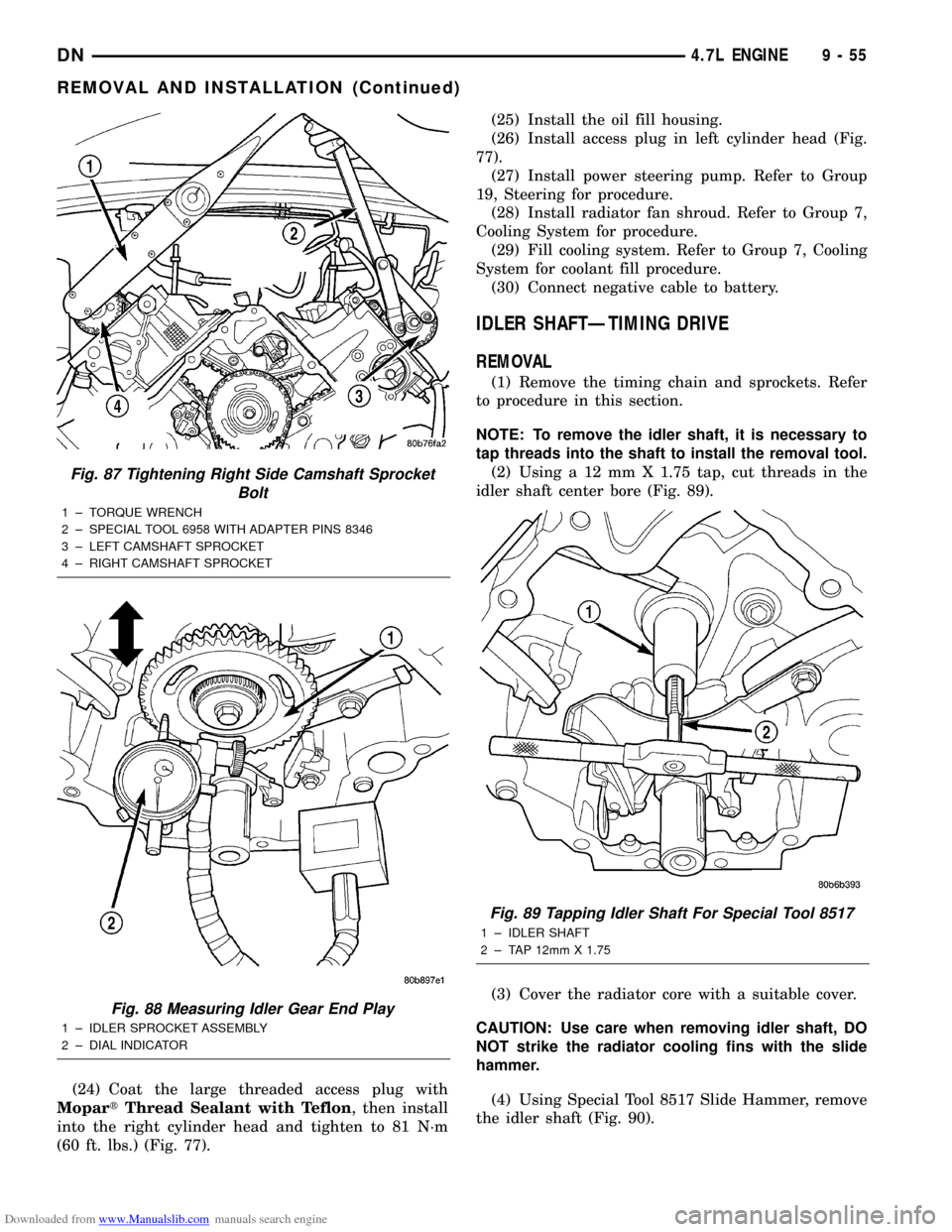
(2) Using a 12 mm X 1.75 tap, cut threads in the
idler shaft center bore (Fig. 89).
(3) Cover the radiator core with a suitable cover.
CAUTION: Use care when removing idler shaft, DO
NOT strike the radiator cooling fins with the slide
hammer.
(4) Using Special Tool 8517 Slide Hammer, remove
the idler shaft (Fig. 90).
Fig. 87 Tightening Right Side Camshaft Sprocket
Bolt
1 ± TORQUE WRENCH
2 ± SPECIAL TOOL 6958 WITH ADAPTER PINS 8346
3 ± LEFT CAMSHAFT SPROCKET
4 ± RIGHT CAMSHAFT SPROCKET
Fig. 88 Measuring Idler Gear End Play
1 ± IDLER SPROCKET ASSEMBLY
2 ± DIAL INDICATOR
Fig. 89 Tapping Idler Shaft For Special Tool 8517
1 ± IDLER SHAFT
2 ± TAP 12mm X 1.75
DN4.7L ENGINE 9 - 55
REMOVAL AND INSTALLATION (Continued)
Page 75 of 193
Downloaded from www.Manualslib.com manuals search engine NOTE: Once the oil pressure relief valve, cup plug,
and pin are removed, the pump assembly must be
replaced.
(3) If it is necessary to remove the pressure relief
valve, drive the roll pin from pump housing and
remove cup plug, spring and valve.
ASSEMBLE
(1) Wash all parts in a suitable solvent and inspect
carefully for damage or wear.
(2) Install inner and outer rotors
(3) Install oil pump cover plate and install cover
bolts and tighten them to 12 N´m (105 in. lbs.).
(4) Prime oil pump before installation by filling
rotor cavity with engine oil.
(5) If oil pressure is low and pump is within spec-
ifications, inspect for worn engine bearings or other
causes for oil pressure loss.
CLEANING AND INSPECTION
INTAKE MANIFOLD
CLEANING
NOTE: There is NO approved repair procedure for
the intake manifold. If severe damage is found dur-
ing inspection, the intake manifold must be
replaced.
Before installing the intake manifold thoroughly
clean the mating surfaces. Use a suitable cleaning
solvent, then air dry.
INSPECTION
(1) Inspect the intake sealing surface for cracks,
nicks and distortion.
(2) Inspect the intake manifold vacuum hose fit-
tings for looseness or blockage.
(3) Inspect the manifold to throttle body mating
surface for cracks, nicks and distortion.
EXHAUST MANIFOLD
CLEANING
(1) Clean the exhaust manifold using a suitable
cleaning solvent, then allow to air dry.
(2) Clean all gasket residue from the manifold
mating surface.
INSPECTION
(1) Inspect the exhaust manifold for cracks in the
mating surface and at every mounting bolt hole.
(2) Using a straight edge and a feeler gauge, check
the mating surface for warp and twist.(3) Inspect the manifold to exhaust pipe mating
surface for cracks, gouges, or other damage that
would prevent sealing.
CYLINDER HEADS
CLEANING
CYLINDER HEAD GASKET SURFACE PREPARATION
To ensure engine gasket sealing, proper surface
preparation must be performed, especially with the
use of aluminum engine components.
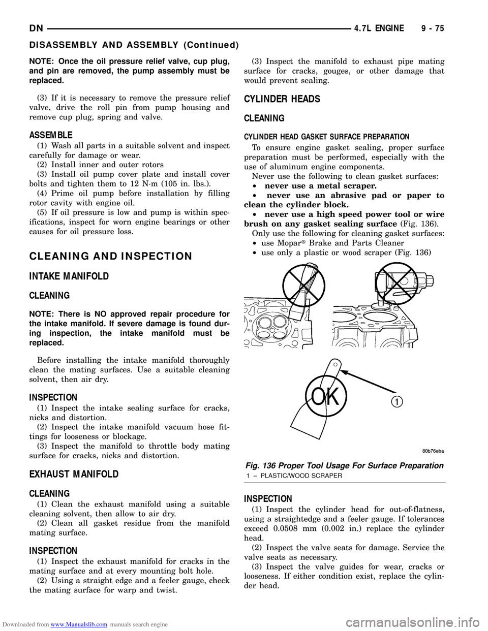
Never use the following to clean gasket surfaces:
²never use a metal scraper.
²never use an abrasive pad or paper to
clean the cylinder block.
²never use a high speed power tool or wire
brush on any gasket sealing surface(Fig. 136).
Only use the following for cleaning gasket surfaces:
²use MopartBrake and Parts Cleaner
²use only a plastic or wood scraper (Fig. 136)
INSPECTION
(1) Inspect the cylinder head for out-of-flatness,
using a straightedge and a feeler gauge. If tolerances
exceed 0.0508 mm (0.002 in.) replace the cylinder
head.
(2) Inspect the valve seats for damage. Service the
valve seats as necessary.
(3) Inspect the valve guides for wear, cracks or
looseness. If either condition exist, replace the cylin-
der head.
Fig. 136 Proper Tool Usage For Surface Preparation
1 ± PLASTIC/WOOD SCRAPER
DN4.7L ENGINE 9 - 75
DISASSEMBLY AND ASSEMBLY (Continued)
Page 78 of 193
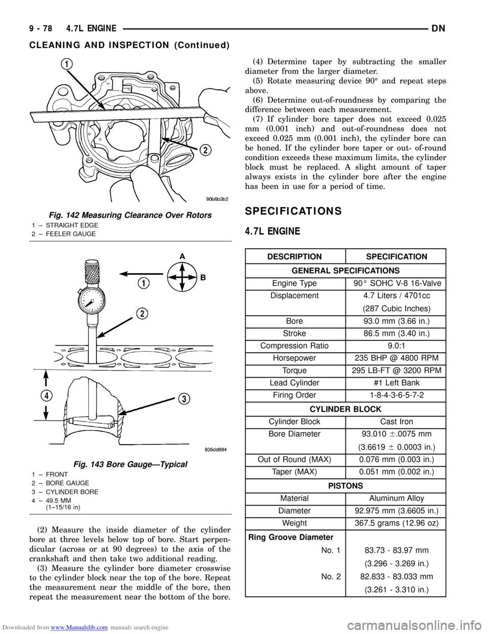
Downloaded from www.Manualslib.com manuals search engine (2) Measure the inside diameter of the cylinder
bore at three levels below top of bore. Start perpen-
dicular (across or at 90 degrees) to the axis of the
crankshaft and then take two additional reading.
(3) Measure the cylinder bore diameter crosswise
to the cylinder block near the top of the bore. Repeat
the measurement near the middle of the bore, then
repeat the measurement near the bottom of the bore.(4) Determine taper by subtracting the smaller
diameter from the larger diameter.
(5) Rotate measuring device 90É and repeat steps
above.
(6) Determine out-of-roundness by comparing the
difference between each measurement.
(7) If cylinder bore taper does not exceed 0.025
mm (0.001 inch) and out-of-roundness does not
exceed 0.025 mm (0.001 inch), the cylinder bore can
be honed. If the cylinder bore taper or out- of-round
condition exceeds these maximum limits, the cylinder
block must be replaced. A slight amount of taper
always exists in the cylinder bore after the engine
has been in use for a period of time.
SPECIFICATIONS
4.7L ENGINE
DESCRIPTION SPECIFICATION
GENERAL SPECIFICATIONS
Engine Type 90É SOHC V-8 16-Valve
Displacement 4.7 Liters / 4701cc
(287 Cubic Inches)
Bore 93.0 mm (3.66 in.)
Stroke 86.5 mm (3.40 in.)
Compression Ratio 9.0:1
Horsepower 235 BHP @ 4800 RPM
Torque 295 LB-FT @ 3200 RPM
Lead Cylinder #1 Left Bank
Firing Order 1-8-4-3-6-5-7-2
CYLINDER BLOCK
Cylinder Block Cast Iron
Bore Diameter 93.0106.0075 mm
(3.661960.0003 in.)
Out of Round (MAX) 0.076 mm (0.003 in.)
Taper (MAX) 0.051 mm (0.002 in.)
PISTONS
Material Aluminum Alloy
Diameter 92.975 mm (3.6605 in.)
Weight 367.5 grams (12.96 oz)
Ring Groove Diameter
No. 1 83.73 - 83.97 mm
(3.296 - 3.269 in.)
No. 2 82.833 - 83.033 mm
(3.261 - 3.310 in.)
Fig. 142 Measuring Clearance Over Rotors
1 ± STRAIGHT EDGE
2 ± FEELER GAUGE
Fig. 143 Bore GaugeÐTypical
1 ± FRONT
2 ± BORE GAUGE
3 ± CYLINDER BORE
4 ± 49.5 MM
(1±15/16 in)
9 - 78 4.7L ENGINEDN
CLEANING AND INSPECTION (Continued)
Page 89 of 193
Downloaded from www.Manualslib.com manuals search engine EXHAUST MANIFOLD
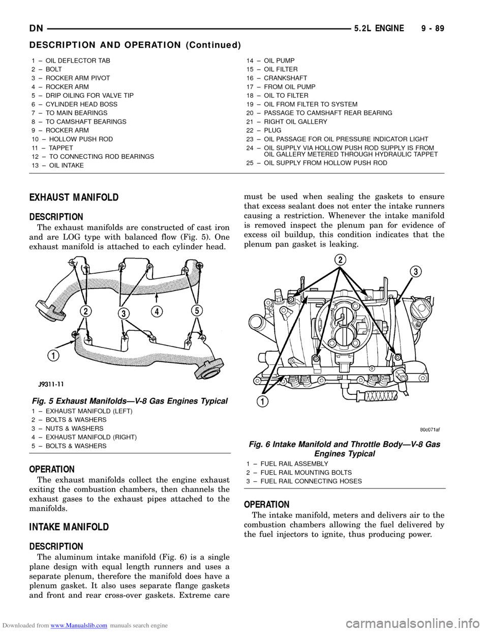
DESCRIPTION
The exhaust manifolds are constructed of cast iron
and are LOG type with balanced flow (Fig. 5). One
exhaust manifold is attached to each cylinder head.
OPERATION
The exhaust manifolds collect the engine exhaust
exiting the combustion chambers, then channels the
exhaust gases to the exhaust pipes attached to the
manifolds.
INTAKE MANIFOLD
DESCRIPTION
The aluminum intake manifold (Fig. 6) is a single
plane design with equal length runners and uses a
separate plenum, therefore the manifold does have a
plenum gasket. It also uses separate flange gaskets
and front and rear cross-over gaskets. Extreme caremust be used when sealing the gaskets to ensure
that excess sealant does not enter the intake runners
causing a restriction. Whenever the intake manifold
is removed inspect the plenum pan for evidence of
excess oil buildup, this condition indicates that the
plenum pan gasket is leaking.
OPERATION
The intake manifold, meters and delivers air to the
combustion chambers allowing the fuel delivered by
the fuel injectors to ignite, thus producing power.
1 ± OIL DEFLECTOR TAB
2 ± BOLT
3 ± ROCKER ARM PIVOT
4 ± ROCKER ARM
5 ± DRIP OILING FOR VALVE TIP
6 ± CYLINDER HEAD BOSS
7 ± TO MAIN BEARINGS
8 ± TO CAMSHAFT BEARINGS
9 ± ROCKER ARM
10 ± HOLLOW PUSH ROD
11 ± TAPPET
12 ± TO CONNECTING ROD BEARINGS
13 ± OIL INTAKE14 ± OIL PUMP
15 ± OIL FILTER
16 ± CRANKSHAFT
17 ± FROM OIL PUMP
18 ± OIL TO FILTER
19 ± OIL FROM FILTER TO SYSTEM
20 ± PASSAGE TO CAMSHAFT REAR BEARING
21 ± RIGHT OIL GALLERY
22 ± PLUG
23 ± OIL PASSAGE FOR OIL PRESSURE INDICATOR LIGHT
24 ± OIL SUPPLY VIA HOLLOW PUSH ROD SUPPLY IS FROM
OIL GALLERY METERED THROUGH HYDRAULIC TAPPET
25 ± OIL SUPPLY FROM HOLLOW PUSH ROD
Fig. 5 Exhaust ManifoldsÐV-8 Gas Engines Typical
1 ± EXHAUST MANIFOLD (LEFT)
2 ± BOLTS & WASHERS
3 ± NUTS & WASHERS
4 ± EXHAUST MANIFOLD (RIGHT)
5 ± BOLTS & WASHERS
Fig. 6 Intake Manifold and Throttle BodyÐV-8 Gas
Engines Typical
1 ± FUEL RAIL ASSEMBLY
2 ± FUEL RAIL MOUNTING BOLTS
3 ± FUEL RAIL CONNECTING HOSES
DN5.2L ENGINE 9 - 89
DESCRIPTION AND OPERATION (Continued)
Page 103 of 193
Downloaded from www.Manualslib.com manuals search engine (9) Disconnect the accelerator linkage.
(10) Remove throttle body.
(11) Perform the Fuel System Pressure release
procedure (refer to Group 14, fuel System).
(12) Disconnect the fuel supply line.
(13) Disconnect the starter wires.
(14) Disconnect the oil pressure sending unit wire.
(15) Discharge the air conditioning system, if
equipped (refer to Group 24, Heating and Air Condi-
tioning for service procedures).
(16) Disconnect the air conditioning hoses.
(17) Disconnect the power steering hoses, if
equipped.
(18) Remove starter motor (refer to Group 8B, Bat-
tery/Starter/Generator Service).
(19) Remove the generator (refer to Group 8B, Bat-
tery/Starter/Generator Service).
(20) Raise and support the vehicle on a hoist.
(21) Disconnect exhaust pipe at manifold.
(22) Refer to Group 21, Transmissions for trans-
mission removal.
CAUTION: DO NOT lift the engine by the intake
manifold.
(23) Install an engine lifting fixture.
(24) The engine and front driving axle (engine/ax-
le/transmission) are connected through insulators
and support brackets. Separate the engine as follows:
²LEFT SIDEÐRemove 2 bolts attaching
(engine/pinion nose/transmission) bracket to trans-
mission bell housing. Remove 2 bracket to pinion
nose adaptor bolts. Separate engine from insulator by
removing upper nut washer assembly and bolt from
engine support bracket.
²RIGHT SIDEÐRemove 2 bracket to axle (dis-
connect housing) bolts and a bracket to bell housing
bolt. Separate engine from insulator by removing
upper nut washer assembly and bolt from engine
support bracket.
(25) Lower the vehicle.
(26) Install engine assembly on engine repair
stand.
INSTALLATION
(1) Remove engine from the repair stand and posi-
tion in the engine compartment.
(2) Install an engine support fixture.
(3) Raise and support the vehicle on a hoist.
(4) Install the engine front mounts.
(5) Refer to Group, 21 Transmissions for transmis-
sion installation
(6) Install the inspection plate.
(7) Remove transmission support.
(8) Install exhaust pipe to manifold.
(9) Lower the vehicle.
(10) Remove engine lifting fixture.(11) Install the generator (refer to Group 8B, Bat-
tery/Starter/Generator Service).
(12) Install starter motor (refer to Group 8B, Bat-
tery/Starter/Generator Service).
(13) Connect power steering hoses, if equipped.
(14) Connect air conditioning hoses.
(15) Evacuate and charge the air conditioning sys-
tem, if equipped (refer to Group 24, Heater and Air
Conditioning for service procedures).
(16) Using a new gasket, install throttle body.
Tighten the throttle body bolts to 23 N´m (200 in.
lbs.) torque.
(17) Connect the accelerator linkage.
(18) Connect the starter wires.
(19) Connect the oil pressure sending unit wire.
(20) Install the distributor cap and wiring.
(21) Connect the vacuum supply lines to the
intake manifold.
(22) Connect the fuel supply lines.
(23) Install the radiator (refer to Group 7, Cooling
System). Connect the radiator hoses and heater
hoses.
(24) Install fan shroud in position.
(25) Fill cooling system (refer to Group 7, Cooling
System for the proper procedure).
(26) Install the air cleaner.
(27) Install the battery.
(28) Warm engine and adjust.
(29) Install hood and line up with the scribe
marks.
(30) Road test vehicle.
INTAKE MANIFOLD
REMOVAL
(1) Disconnect the battery negative cable.
(2) Drain the cooling system. Refer to COOLING
SYSTEM.
(3) Remove the A/C compressor. Refer to HEAT-
ING and AIR CONDITIONING.
(4) Remove the generator. Refer to CHARGING
SYSTEM.
(5) Remove the accessory drive bracket.
(6) Remove the air cleaner assembly and air inlet
hose.
(7) Perform the fuel pressure release procedure.
Refer to FUEL SYSTEM.
(8) Disconnect the fuel supply line from the fuel
rail. Refer to FUEL SYSTEM.
(9) Disconnect the accelerator linkage and, if so
equipped, the speed control and transmission kick-
down cables.
(10) Remove the distributor cap and wires.
(11) Disconnect the coil wires.
(12) Disconnect the coolant temperature sending
unit wire.
DN5.2L ENGINE 9 - 103
REMOVAL AND INSTALLATION (Continued)
Page 110 of 193
Downloaded from www.Manualslib.com manuals search engine (7) Position the fan shroud and install the bolts.
Tighten the retainer bolts to 11 N´m (95 in. lbs.)
torque.
(8) Connect the negative cable to the battery.
TIMING CHAIN COVER
(1) Disconnect the negative cable from the battery.
(2) Drain cooling system (refer to Group 7, Cooling
System).
(3) Remove the serpentine belt (refer to Group 7,
Cooling System).
(4) Remove water pump (refer to Group 7, Cooling
System).
(5) Remove power steering pump (refer to Group
19, Steering).
(6) Remove vibration damper.
(7) Remove fuel lines (refer to Group 14, Fuel Sys-
tem).
(8) Loosen oil pan bolts and remove the front bolt
at each side.
(9) Remove the cover bolts.
(10) Remove chain case cover and gasket using
extreme caution to avoid damaging oil pan gasket.
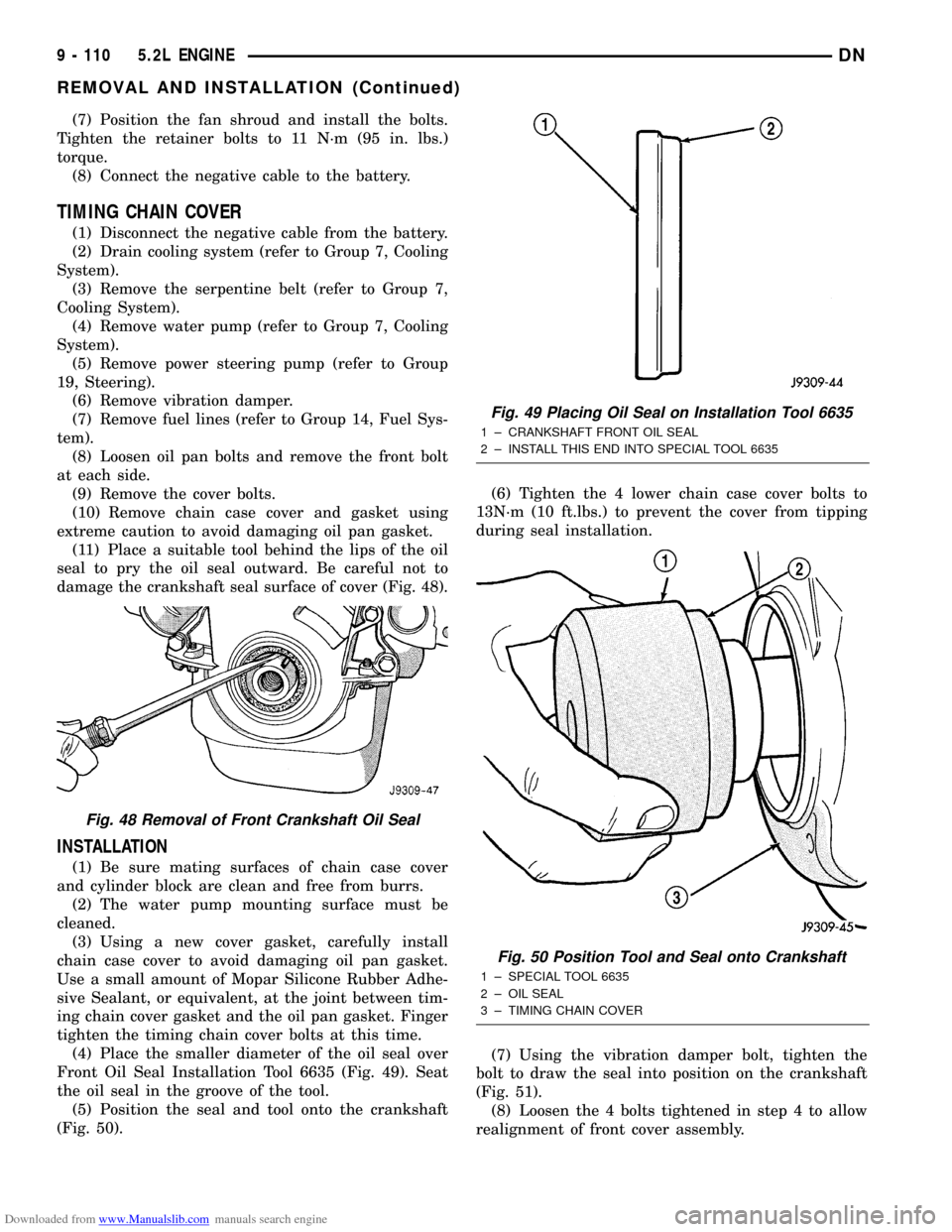
(11) Place a suitable tool behind the lips of the oil
seal to pry the oil seal outward. Be careful not to
damage the crankshaft seal surface of cover (Fig. 48).
INSTALLATION
(1) Be sure mating surfaces of chain case cover
and cylinder block are clean and free from burrs.
(2) The water pump mounting surface must be
cleaned.
(3) Using a new cover gasket, carefully install
chain case cover to avoid damaging oil pan gasket.
Use a small amount of Mopar Silicone Rubber Adhe-
sive Sealant, or equivalent, at the joint between tim-
ing chain cover gasket and the oil pan gasket. Finger
tighten the timing chain cover bolts at this time.
(4) Place the smaller diameter of the oil seal over
Front Oil Seal Installation Tool 6635 (Fig. 49). Seat
the oil seal in the groove of the tool.
(5) Position the seal and tool onto the crankshaft
(Fig. 50).(6) Tighten the 4 lower chain case cover bolts to
13N´m (10 ft.lbs.) to prevent the cover from tipping
during seal installation.
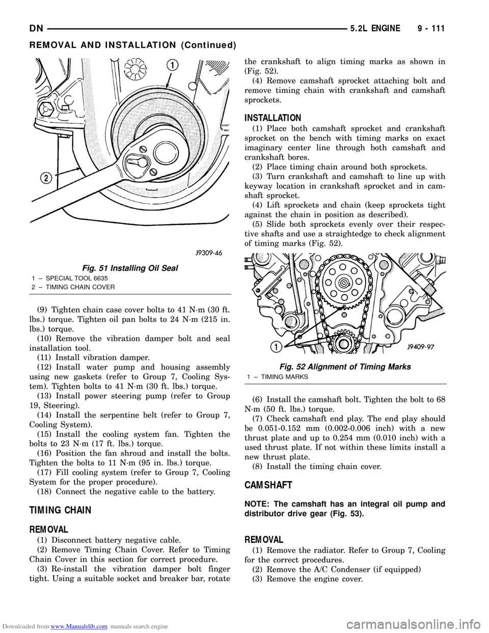
(7) Using the vibration damper bolt, tighten the
bolt to draw the seal into position on the crankshaft
(Fig. 51).
(8) Loosen the 4 bolts tightened in step 4 to allow
realignment of front cover assembly.
Fig. 48 Removal of Front Crankshaft Oil Seal
Fig. 49 Placing Oil Seal on Installation Tool 6635
1 ± CRANKSHAFT FRONT OIL SEAL
2 ± INSTALL THIS END INTO SPECIAL TOOL 6635
Fig. 50 Position Tool and Seal onto Crankshaft
1 ± SPECIAL TOOL 6635
2 ± OIL SEAL
3 ± TIMING CHAIN COVER
9 - 110 5.2L ENGINEDN
REMOVAL AND INSTALLATION (Continued)
Page 111 of 193
Downloaded from www.Manualslib.com manuals search engine (9) Tighten chain case cover bolts to 41 N´m (30 ft.
lbs.) torque. Tighten oil pan bolts to 24 N´m (215 in.
lbs.) torque.
(10) Remove the vibration damper bolt and seal
installation tool.
(11) Install vibration damper.
(12) Install water pump and housing assembly
using new gaskets (refer to Group 7, Cooling Sys-
tem). Tighten bolts to 41 N´m (30 ft. lbs.) torque.
(13) Install power steering pump (refer to Group
19, Steering).
(14) Install the serpentine belt (refer to Group 7,
Cooling System).
(15) Install the cooling system fan. Tighten the
bolts to 23 N´m (17 ft. lbs.) torque.
(16) Position the fan shroud and install the bolts.
Tighten the bolts to 11 N´m (95 in. lbs.) torque.
(17) Fill cooling system (refer to Group 7, Cooling
System for the proper procedure).
(18) Connect the negative cable to the battery.
TIMING CHAIN
REMOVAL
(1) Disconnect battery negative cable.
(2) Remove Timing Chain Cover. Refer to Timing
Chain Cover in this section for correct procedure.
(3) Re-install the vibration damper bolt finger
tight. Using a suitable socket and breaker bar, rotatethe crankshaft to align timing marks as shown in
(Fig. 52).
(4) Remove camshaft sprocket attaching bolt and
remove timing chain with crankshaft and camshaft
sprockets.
INSTALLATION
(1) Place both camshaft sprocket and crankshaft
sprocket on the bench with timing marks on exact
imaginary center line through both camshaft and
crankshaft bores.
(2) Place timing chain around both sprockets.
(3) Turn crankshaft and camshaft to line up with
keyway location in crankshaft sprocket and in cam-
shaft sprocket.
(4) Lift sprockets and chain (keep sprockets tight
against the chain in position as described).
(5) Slide both sprockets evenly over their respec-
tive shafts and use a straightedge to check alignment
of timing marks (Fig. 52).
(6) Install the camshaft bolt. Tighten the bolt to 68
N´m (50 ft. lbs.) torque.
(7) Check camshaft end play. The end play should
be 0.051-0.152 mm (0.002-0.006 inch) with a new
thrust plate and up to 0.254 mm (0.010 inch) with a
used thrust plate. If not within these limits install a
new thrust plate.
(8) Install the timing chain cover.
CAMSHAFT
NOTE: The camshaft has an integral oil pump and
distributor drive gear (Fig. 53).
REMOVAL
(1) Remove the radiator. Refer to Group 7, Cooling
for the correct procedures.
(2) Remove the A/C Condenser (if equipped)
(3) Remove the engine cover.
Fig. 51 Installing Oil Seal
1 ± SPECIAL TOOL 6635
2 ± TIMING CHAIN COVER
Fig. 52 Alignment of Timing Marks
1 ± TIMING MARKS
DN5.2L ENGINE 9 - 111
REMOVAL AND INSTALLATION (Continued)
Page 140 of 193
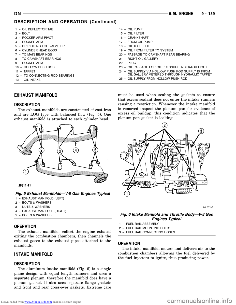
Downloaded from www.Manualslib.com manuals search engine EXHAUST MANIFOLD
DESCRIPTION
The exhaust manifolds are constructed of cast iron
and are LOG type with balanced flow (Fig. 5). One
exhaust manifold is attached to each cylinder head.
OPERATION
The exhaust manifolds collect the engine exhaust
exiting the combustion chambers, then channels the
exhaust gases to the exhaust pipes attached to the
manifolds.
INTAKE MANIFOLD
DESCRIPTION
The aluminum intake manifold (Fig. 6) is a single
plane design with equal length runners and uses a
separate plenum, therefore the manifold does have a
plenum gasket. It also uses separate flange gaskets
and front and rear cross-over gaskets. Extreme caremust be used when sealing the gaskets to ensure
that excess sealant does not enter the intake runners
causing a restriction. Whenever the intake manifold
is removed inspect the plenum pan for evidence of
excess oil buildup, this condition indicates that the
plenum pan gasket is leaking.
OPERATION
The intake manifold, meters and delivers air to the
combustion chambers allowing the fuel delivered by
the fuel injectors to ignite, thus producing power.
1 ± OIL DEFLECTOR TAB
2 ± BOLT
3 ± ROCKER ARM PIVOT
4 ± ROCKER ARM
5 ± DRIP OILING FOR VALVE TIP
6 ± CYLINDER HEAD BOSS
7 ± TO MAIN BEARINGS
8 ± TO CAMSHAFT BEARINGS
9 ± ROCKER ARM
10 ± HOLLOW PUSH ROD
11 ± TAPPET
12 ± TO CONNECTING ROD BEARINGS
13 ± OIL INTAKE14 ± OIL PUMP
15 ± OIL FILTER
16 ± CRANKSHAFT
17 ± FROM OIL PUMP
18 ± OIL TO FILTER
19 ± OIL FROM FILTER TO SYSTEM
20 ± PASSAGE TO CAMSHAFT REAR BEARING
21 ± RIGHT OIL GALLERY
22 ± PLUG
23 ± OIL PASSAGE FOR OIL PRESSURE INDICATOR LIGHT
24 ± OIL SUPPLY VIA HOLLOW PUSH ROD SUPPLY IS FROM
OIL GALLERY METERED THROUGH HYDRAULIC TAPPET
25 ± OIL SUPPLY FROM HOLLOW PUSH ROD
Fig. 5 Exhaust ManifoldsÐV-8 Gas Engines Typical
1 ± EXHAUST MANIFOLD (LEFT)
2 ± BOLTS & WASHERS
3 ± NUTS & WASHERS
4 ± EXHAUST MANIFOLD (RIGHT)
5 ± BOLTS & WASHERS
Fig. 6 Intake Manifold and Throttle BodyÐV-8 Gas
Engines Typical
1 ± FUEL RAIL ASSEMBLY
2 ± FUEL RAIL MOUNTING BOLTS
3 ± FUEL RAIL CONNECTING HOSES
DN5.9L ENGINE 9 - 139
DESCRIPTION AND OPERATION (Continued)
Page 143 of 193
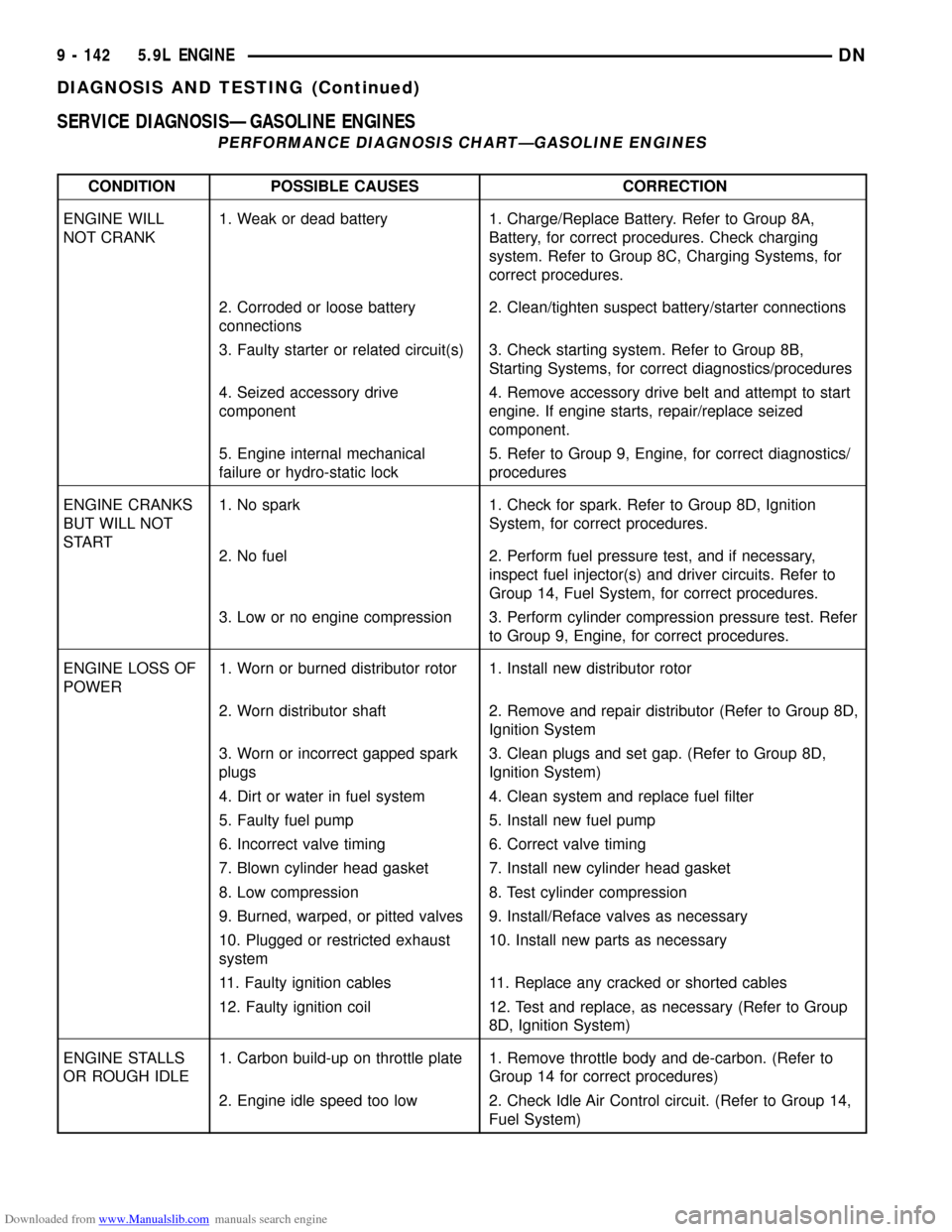
Downloaded from www.Manualslib.com manuals search engine SERVICE DIAGNOSISÐGASOLINE ENGINES
PERFORMANCE DIAGNOSIS CHARTÐGASOLINE ENGINES
CONDITION POSSIBLE CAUSES CORRECTION
ENGINE WILL
NOT CRANK1. Weak or dead battery 1. Charge/Replace Battery. Refer to Group 8A,
Battery, for correct procedures. Check charging
system. Refer to Group 8C, Charging Systems, for
correct procedures.
2. Corroded or loose battery
connections2. Clean/tighten suspect battery/starter connections
3. Faulty starter or related circuit(s) 3. Check starting system. Refer to Group 8B,
Starting Systems, for correct diagnostics/procedures
4. Seized accessory drive
component4. Remove accessory drive belt and attempt to start
engine. If engine starts, repair/replace seized
component.
5. Engine internal mechanical
failure or hydro-static lock5. Refer to Group 9, Engine, for correct diagnostics/
procedures
ENGINE CRANKS
BUT WILL NOT
START1. No spark 1. Check for spark. Refer to Group 8D, Ignition
System, for correct procedures.
2. No fuel 2. Perform fuel pressure test, and if necessary,
inspect fuel injector(s) and driver circuits. Refer to
Group 14, Fuel System, for correct procedures.
3. Low or no engine compression 3. Perform cylinder compression pressure test. Refer
to Group 9, Engine, for correct procedures.
ENGINE LOSS OF
POWER1. Worn or burned distributor rotor 1. Install new distributor rotor
2. Worn distributor shaft 2. Remove and repair distributor (Refer to Group 8D,
Ignition System
3. Worn or incorrect gapped spark
plugs3. Clean plugs and set gap. (Refer to Group 8D,
Ignition System)
4. Dirt or water in fuel system 4. Clean system and replace fuel filter
5. Faulty fuel pump 5. Install new fuel pump
6. Incorrect valve timing 6. Correct valve timing
7. Blown cylinder head gasket 7. Install new cylinder head gasket
8. Low compression 8. Test cylinder compression
9. Burned, warped, or pitted valves 9. Install/Reface valves as necessary
10. Plugged or restricted exhaust
system10. Install new parts as necessary
11. Faulty ignition cables 11. Replace any cracked or shorted cables
12. Faulty ignition coil 12. Test and replace, as necessary (Refer to Group
8D, Ignition System)
ENGINE STALLS
OR ROUGH IDLE1. Carbon build-up on throttle plate 1. Remove throttle body and de-carbon. (Refer to
Group 14 for correct procedures)
2. Engine idle speed too low 2. Check Idle Air Control circuit. (Refer to Group 14,
Fuel System)
9 - 142 5.9L ENGINEDN
DIAGNOSIS AND TESTING (Continued)