drain bolt DODGE DURANGO 1999 1.G Owner's Guide
[x] Cancel search | Manufacturer: DODGE, Model Year: 1999, Model line: DURANGO, Model: DODGE DURANGO 1999 1.GPages: 193, PDF Size: 5.65 MB
Page 183 of 193

Downloaded from www.Manualslib.com manuals search engine ASSEMBLE
(1) Install pump rotors and shaft, using new parts
as required.
(2) Position the oil pump cover onto the pump
body. Tighten cover bolts to 11 N´m (95 in. lbs.)
torque.
(3) Install the relief valve and spring. Insert the
cotter pin.
(4) Tap on a new retainer cap.
(5) Prime oil pump before installation by filling
rotor cavity with engine oil.
CLEANING AND INSPECTION
CYLINDER HEAD COVER
CLEANING
Clean cylinder head cover gasket surface.
Clean head rail, if necessary.
INSPECTION
Inspect cover for distortion and straighten, if nec-
essary.
Check the gasket for use in head cover installation.
If damaged, use a new gasket.
CYLINDER HEAD ASSEMBLY
CLEANING
Clean all surfaces of cylinder block and cylinder
heads.
Clean cylinder block front and rear gasket surfaces
using a suitable solvent.
INSPECTION
Inspect all surfaces with a straightedge if there is
any reason to suspect leakage. If out-of-flatness
exceeds 0.00075 mm/mm (0.00075 inch/inch) times
the span length in inches in any direction, either
replace head or lightly machine the head surface.
FOR EXAMPLE:A 305 mm (12 inch) span is
0.102 mm (0.004 inch) out-of-flat. The allowable out-
of-flat is 305 X 0.00075 (12 X 0.00075) equals 0.23
mm (0.009 inch). This amount of out-of-flat is accept-
able.
The cylinder head surface finish should be
1.78-3.00 microns (70-125 microinches).
PISTON AND CONNECTING ROD ASSEMBLY
INSPECTION
Check the crankshaft connecting rod journal for
excessive wear, taper and scoring.
Check the cylinder block bore for out-of-round,
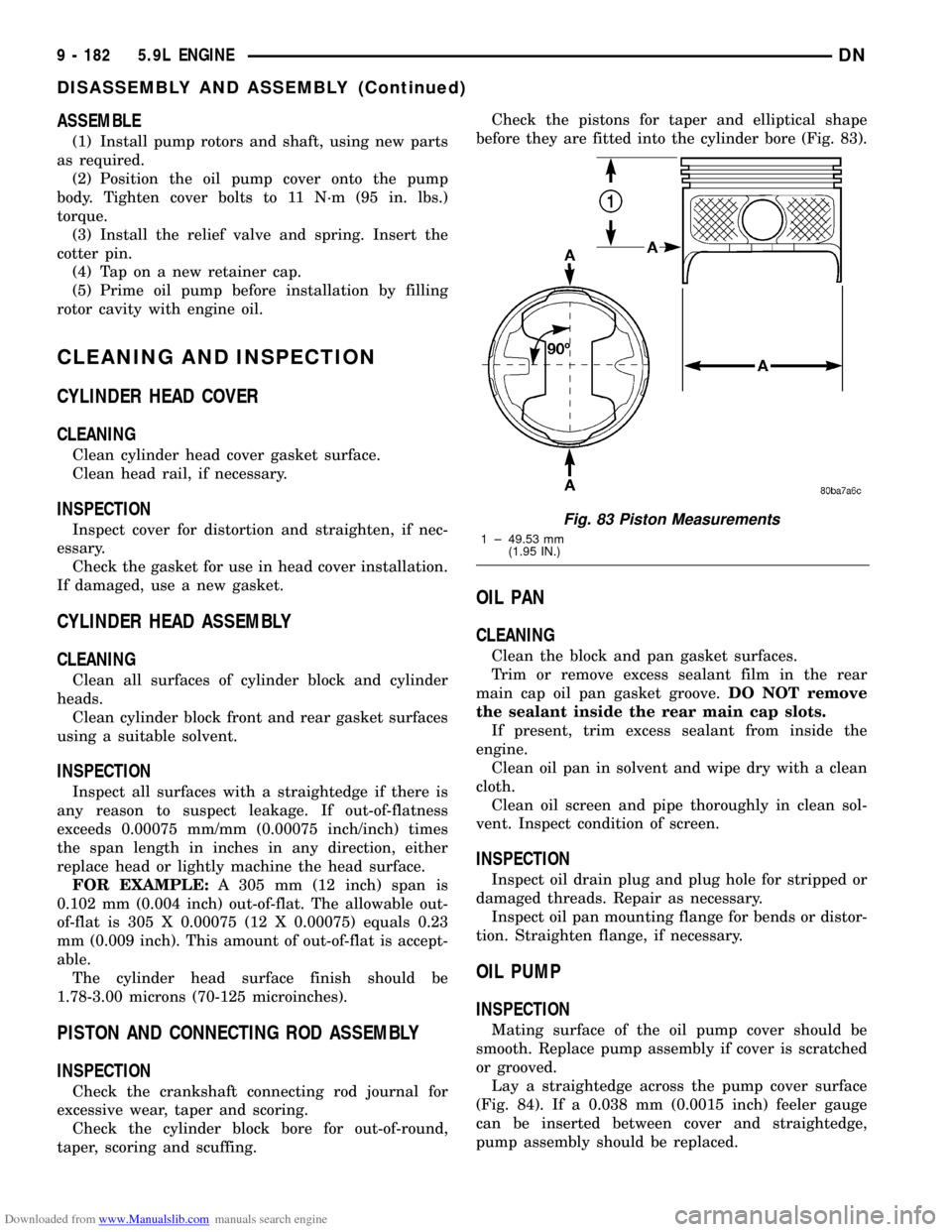
taper, scoring and scuffing.Check the pistons for taper and elliptical shape
before they are fitted into the cylinder bore (Fig. 83).
OIL PAN
CLEANING
Clean the block and pan gasket surfaces.
Trim or remove excess sealant film in the rear
main cap oil pan gasket groove.DO NOT remove
the sealant inside the rear main cap slots.
If present, trim excess sealant from inside the
engine.
Clean oil pan in solvent and wipe dry with a clean
cloth.
Clean oil screen and pipe thoroughly in clean sol-
vent. Inspect condition of screen.
INSPECTION
Inspect oil drain plug and plug hole for stripped or
damaged threads. Repair as necessary.
Inspect oil pan mounting flange for bends or distor-
tion. Straighten flange, if necessary.
OIL PUMP
INSPECTION
Mating surface of the oil pump cover should be
smooth. Replace pump assembly if cover is scratched
or grooved.
Lay a straightedge across the pump cover surface
(Fig. 84). If a 0.038 mm (0.0015 inch) feeler gauge
can be inserted between cover and straightedge,
pump assembly should be replaced.
Fig. 83 Piston Measurements
1 ± 49.53 mm
(1.95 IN.)
9 - 182 5.9L ENGINEDN
DISASSEMBLY AND ASSEMBLY (Continued)
Page 190 of 193

Downloaded from www.Manualslib.com manuals search engine SPECIFICATIONS
TORQUE CHART 5.9L ENGINE
DESCRIPTION N´m Ft. In.
Lbs. Lbs.
Camshaft SprocketÐBolt 68 50 Ð
Camshaft Thrust PlateÐBolts 24 Ð 210
Timing Chain Case CoverÐ
Bolts41 30 Ð
Connecting Rod CapÐBolts 61 45 Ð
Main Bearing CapÐBolts 115 85 Ð
Crankshaft PulleyÐBolts 24 Ð 210
Cylinder HeadÐBolts
Step 1 68 50 Ð
Step 2 143 105 Ð
Cylinder Head CoverÐBolts 11 Ð 95
Engine Support Bracket to
BlockÐ41 30 Ð
Bolts (4WD)
Exhaust Manifold to Cylinder
HeadÐ34 25 Ð
Bolts/Nuts
FlywheelÐBolts 75 55 Ð
Front InsulatorÐThrough
bolt/nut95 70 Ð
Front Insulator to Support
Bracket
ÐStud Nut (4WD) 41 30 Ð
ÐThrough Bolt/Nut (4WD) 102 75 Ð
Front Insulator to BlockÐ
Bolts (2WD)95 70 Ð
GeneratorÐMounting Bolt 41 30 Ð
Intake ManifoldÐBolts Refer to Procedure
Oil PanÐBolts 24 Ð 215
Oil PanÐDrain Plug 34 25 Ð
Oil PumpÐAttaching Bolts 41 30 Ð
Oil Pump CoverÐBolts 11 Ð 95
Rear Insulator to BracketÐ 68 50 Ð
Through-Bolt (2WD)
Rear Insulator to
Crossmember41 30 Ð
Support BracketÐNut (2WD)
Rear Insulator to
CrossmemberÐ68 50 Ð
Nuts (4WD)
DESCRIPTION N´m Ft. In.
Lbs. Lbs.
Rear Insulator to
TransmissionÐ68 50 Ð
Bolts (4WD)
Rear Insulator BracketÐBolts 68 50 Ð
(4WD Automatic)
Rear Support Bracket to 41 30 Ð
Crossmember FlangeÐNuts
Rear Support Plate to
Transfer41 30 Ð
CaseÐBolts
Rocker ArmÐBolts 28 21 Ð
Spark Plugs 41 30 Ð
Starter MotorÐMounting Bolts 68 50 Ð
Thermostat HousingÐBolts 25 Ð 225
Throttle BodyÐBolts 23 Ð 200
Torque Converter Drive
PlateÐBolts31 Ð 270
Transfer Case to Insulator 204 105 Ð
Mounting PlateÐNuts
Transmission Support
BracketÐ68 50 Ð
Bolts (2WD)
Vibration DamperÐBolt 244 180 Ð
Water Pump to Timing Chain 41 30 Ð
Case CoverÐBolts
SPECIAL TOOLS
5.9L ENGINE
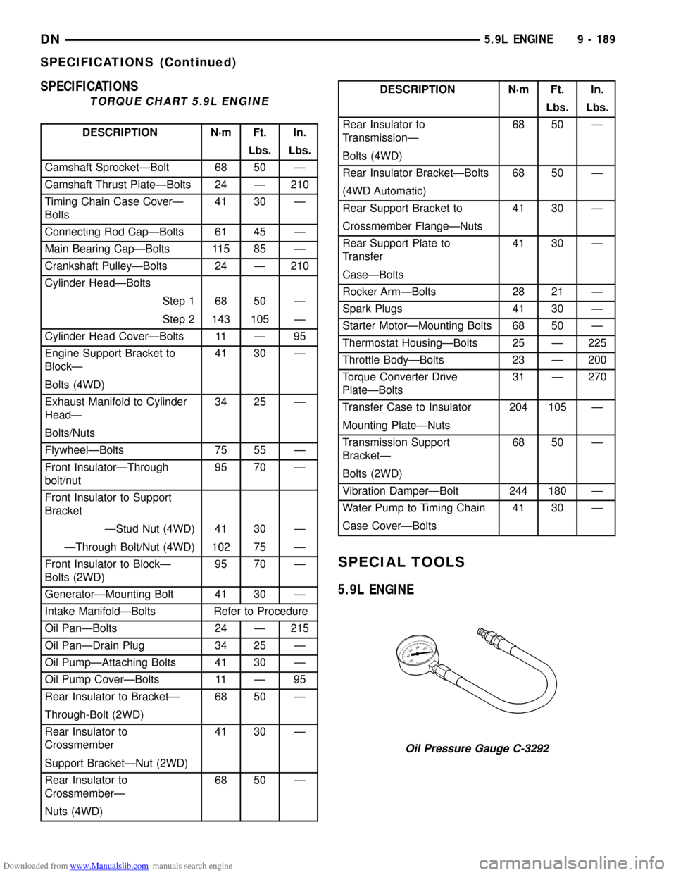
Oil Pressure Gauge C-3292
DN5.9L ENGINE 9 - 189
SPECIFICATIONS (Continued)