5.9L DODGE DURANGO 1999 1.G Repair Manual
[x] Cancel search | Manufacturer: DODGE, Model Year: 1999, Model line: DURANGO, Model: DODGE DURANGO 1999 1.GPages: 193, PDF Size: 5.65 MB
Page 183 of 193
Downloaded from www.Manualslib.com manuals search engine ASSEMBLE
(1) Install pump rotors and shaft, using new parts
as required.
(2) Position the oil pump cover onto the pump
body. Tighten cover bolts to 11 N´m (95 in. lbs.)
torque.
(3) Install the relief valve and spring. Insert the
cotter pin.
(4) Tap on a new retainer cap.
(5) Prime oil pump before installation by filling
rotor cavity with engine oil.
CLEANING AND INSPECTION
CYLINDER HEAD COVER
CLEANING
Clean cylinder head cover gasket surface.
Clean head rail, if necessary.
INSPECTION
Inspect cover for distortion and straighten, if nec-
essary.
Check the gasket for use in head cover installation.
If damaged, use a new gasket.
CYLINDER HEAD ASSEMBLY
CLEANING
Clean all surfaces of cylinder block and cylinder
heads.
Clean cylinder block front and rear gasket surfaces
using a suitable solvent.
INSPECTION
Inspect all surfaces with a straightedge if there is
any reason to suspect leakage. If out-of-flatness
exceeds 0.00075 mm/mm (0.00075 inch/inch) times
the span length in inches in any direction, either
replace head or lightly machine the head surface.
FOR EXAMPLE:A 305 mm (12 inch) span is
0.102 mm (0.004 inch) out-of-flat. The allowable out-
of-flat is 305 X 0.00075 (12 X 0.00075) equals 0.23
mm (0.009 inch). This amount of out-of-flat is accept-
able.
The cylinder head surface finish should be
1.78-3.00 microns (70-125 microinches).
PISTON AND CONNECTING ROD ASSEMBLY
INSPECTION
Check the crankshaft connecting rod journal for
excessive wear, taper and scoring.
Check the cylinder block bore for out-of-round,
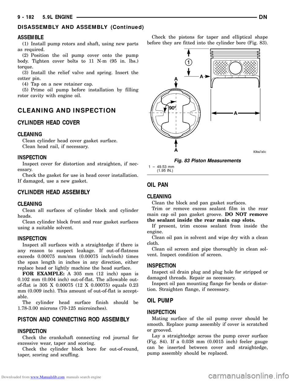
taper, scoring and scuffing.Check the pistons for taper and elliptical shape
before they are fitted into the cylinder bore (Fig. 83).
OIL PAN
CLEANING
Clean the block and pan gasket surfaces.
Trim or remove excess sealant film in the rear
main cap oil pan gasket groove.DO NOT remove
the sealant inside the rear main cap slots.
If present, trim excess sealant from inside the
engine.
Clean oil pan in solvent and wipe dry with a clean
cloth.
Clean oil screen and pipe thoroughly in clean sol-
vent. Inspect condition of screen.
INSPECTION
Inspect oil drain plug and plug hole for stripped or
damaged threads. Repair as necessary.
Inspect oil pan mounting flange for bends or distor-
tion. Straighten flange, if necessary.
OIL PUMP
INSPECTION
Mating surface of the oil pump cover should be
smooth. Replace pump assembly if cover is scratched
or grooved.
Lay a straightedge across the pump cover surface
(Fig. 84). If a 0.038 mm (0.0015 inch) feeler gauge
can be inserted between cover and straightedge,
pump assembly should be replaced.
Fig. 83 Piston Measurements
1 ± 49.53 mm
(1.95 IN.)
9 - 182 5.9L ENGINEDN
DISASSEMBLY AND ASSEMBLY (Continued)
Page 184 of 193
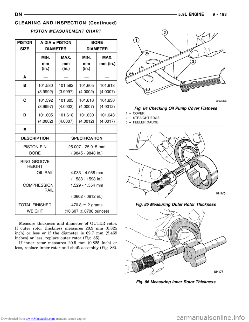
Downloaded from www.Manualslib.com manuals search engine Measure thickness and diameter of OUTER rotor.
If outer rotor thickness measures 20.9 mm (0.825
inch) or less or if the diameter is 62.7 mm (2.469
inches) or less, replace outer rotor (Fig. 85).
If inner rotor measures 20.9 mm (0.825 inch) or
less, replace inner rotor and shaft assembly (Fig. 86).
PISTON MEASUREMENT CHART
PISTON A DIA = PISTON BORE
SIZE DIAMETER DIAMETER
MIN. MAX. MIN. MAX.
mm
(in.)mm
(in.)mm
(in.)mm (in.)
AÐÐÐ Ð
B101.580 101.592 101.605 101.618
(3.9992) (3.9997) (4.0002) (4.0007)
C101.592 101.605 101.618 101.630
(3.9997) (4.0002) (4.0007) (4.0012)
D101.605 101.618 101.630 101.643
(4.0002) (4.0007) (4.0012) (4.0017)
EÐÐÐ Ð
DESCRIPTION SPECIFICATION
PISTON PIN 25.007 - 25.015 mm
BORE (.9845 -.9848 in.)
RING GROOVE
HEIGHT
OIL RAIL 4.033 - 4.058 mm
(.1588 -.1598 in.)
COMPRESSION
RAIL1.529 - 1.554 mm
(.0602 -.0612 in.)
TOTAL FINISHED 470.862 grams
WEIGHT (16.6076.0706 ounces)
Fig. 84 Checking Oil Pump Cover Flatness
1 ± COVER
2 ± STRAIGHT EDGE
3 ± FEELER GAUGE
Fig. 85 Measuring Outer Rotor Thickness
Fig. 86 Measuring Inner Rotor Thickness
DN5.9L ENGINE 9 - 183
CLEANING AND INSPECTION (Continued)
Page 185 of 193
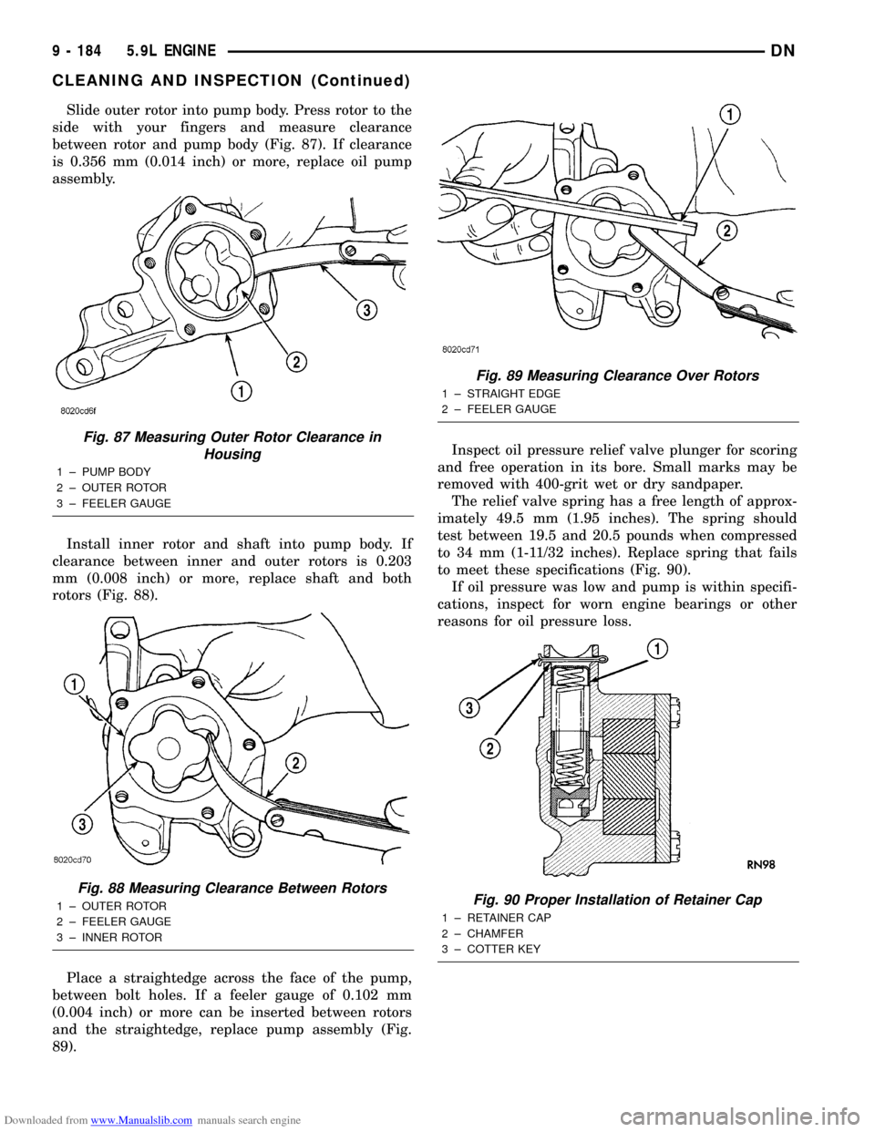
Downloaded from www.Manualslib.com manuals search engine Slide outer rotor into pump body. Press rotor to the
side with your fingers and measure clearance
between rotor and pump body (Fig. 87). If clearance
is 0.356 mm (0.014 inch) or more, replace oil pump
assembly.
Install inner rotor and shaft into pump body. If
clearance between inner and outer rotors is 0.203
mm (0.008 inch) or more, replace shaft and both
rotors (Fig. 88).
Place a straightedge across the face of the pump,
between bolt holes. If a feeler gauge of 0.102 mm
(0.004 inch) or more can be inserted between rotors
and the straightedge, replace pump assembly (Fig.
89).Inspect oil pressure relief valve plunger for scoring
and free operation in its bore. Small marks may be
removed with 400-grit wet or dry sandpaper.
The relief valve spring has a free length of approx-
imately 49.5 mm (1.95 inches). The spring should
test between 19.5 and 20.5 pounds when compressed
to 34 mm (1-11/32 inches). Replace spring that fails
to meet these specifications (Fig. 90).
If oil pressure was low and pump is within specifi-
cations, inspect for worn engine bearings or other
reasons for oil pressure loss.
Fig. 87 Measuring Outer Rotor Clearance in
Housing
1 ± PUMP BODY
2 ± OUTER ROTOR
3 ± FEELER GAUGE
Fig. 88 Measuring Clearance Between Rotors
1 ± OUTER ROTOR
2 ± FEELER GAUGE
3 ± INNER ROTOR
Fig. 89 Measuring Clearance Over Rotors
1 ± STRAIGHT EDGE
2 ± FEELER GAUGE
Fig. 90 Proper Installation of Retainer Cap
1 ± RETAINER CAP
2 ± CHAMFER
3 ± COTTER KEY
9 - 184 5.9L ENGINEDN
CLEANING AND INSPECTION (Continued)
Page 186 of 193
Downloaded from www.Manualslib.com manuals search engine CYLINDER BLOCK
CLEANING
Clean cylinder block thoroughly and check all core
hole plugs for evidence of leaking.
INSPECTION
Examine block for cracks or fractures.
The cylinder walls should be checked for out-of-
round and taper with Cylinder Bore Indicator Tool
C-119. The cylinder block should be bored and honed
with new pistons and rings fitted if:
²The cylinder bores show more than 0.127 mm
(0.005 inch) out-of-round.
²The cylinder bores show a taper of more than
0.254 mm (0.010 inch).
²The cylinder walls are badly scuffed or scored.
Boring and honing operation should be closely coor-
dinated with the fitting of pistons and rings so spec-
ified clearances may be maintained.
Refer to Standard Service Procedures in the begin-
ning of this Group for the proper honing of cylinder
bores.
INTAKE MANIFOLD
CLEANING
Clean manifold in solvent and blow dry with com-
pressed air.
Clean cylinder block front and rear gasket surfaces
using a suitable solvent.
The plenum pan rail must be clean and dry (free of
all foreign material).
INSPECTION
Inspect manifold for cracks.
Inspect mating surfaces of manifold for flatness
with a straightedge.
EXHAUST MANIFOLD
CLEANING
Clean mating surfaces on cylinder head and mani-
fold, wash with solvent and blow dry with com-
pressed air.
INSPECTION
Inspect manifold for cracks, Inspect mating sur-
faces of manifold for flatness with a straight edge.
Seal surfaces must be flat within 0.1 mm (0.004 inch)
overall.
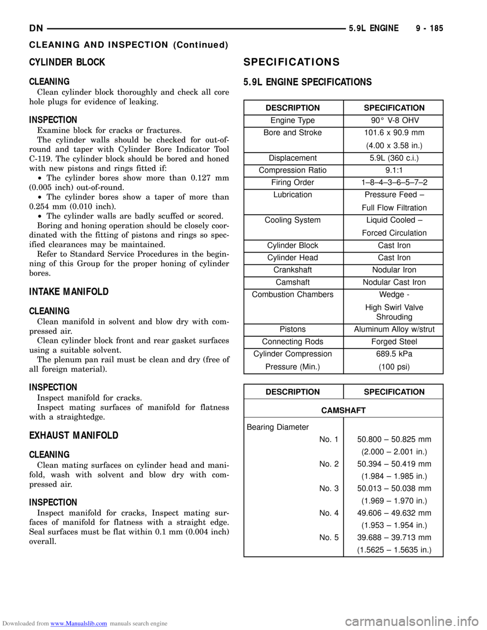
SPECIFICATIONS
5.9L ENGINE SPECIFICATIONS
DESCRIPTION SPECIFICATION
Engine Type 90É V-8 OHV
Bore and Stroke 101.6 x 90.9 mm
(4.00 x 3.58 in.)
Displacement 5.9L (360 c.i.)
Compression Ratio 9.1:1
Firing Order 1±8±4±3±6±5±7±2
Lubrication Pressure Feed ±
Full Flow Filtration
Cooling System Liquid Cooled ±
Forced Circulation
Cylinder Block Cast Iron
Cylinder Head Cast Iron
Crankshaft Nodular Iron
Camshaft Nodular Cast Iron
Combustion Chambers Wedge -
High Swirl Valve
Shrouding
Pistons Aluminum Alloy w/strut
Connecting Rods Forged Steel
Cylinder Compression 689.5 kPa
Pressure (Min.) (100 psi)
DESCRIPTION SPECIFICATION
CAMSHAFT
Bearing Diameter
No. 1 50.800 ± 50.825 mm
(2.000 ± 2.001 in.)
No. 2 50.394 ± 50.419 mm
(1.984 ± 1.985 in.)
No. 3 50.013 ± 50.038 mm
(1.969 ± 1.970 in.)
No. 4 49.606 ± 49.632 mm
(1.953 ± 1.954 in.)
No. 5 39.688 ± 39.713 mm
(1.5625 ± 1.5635 in.)
DN5.9L ENGINE 9 - 185
CLEANING AND INSPECTION (Continued)
Page 187 of 193
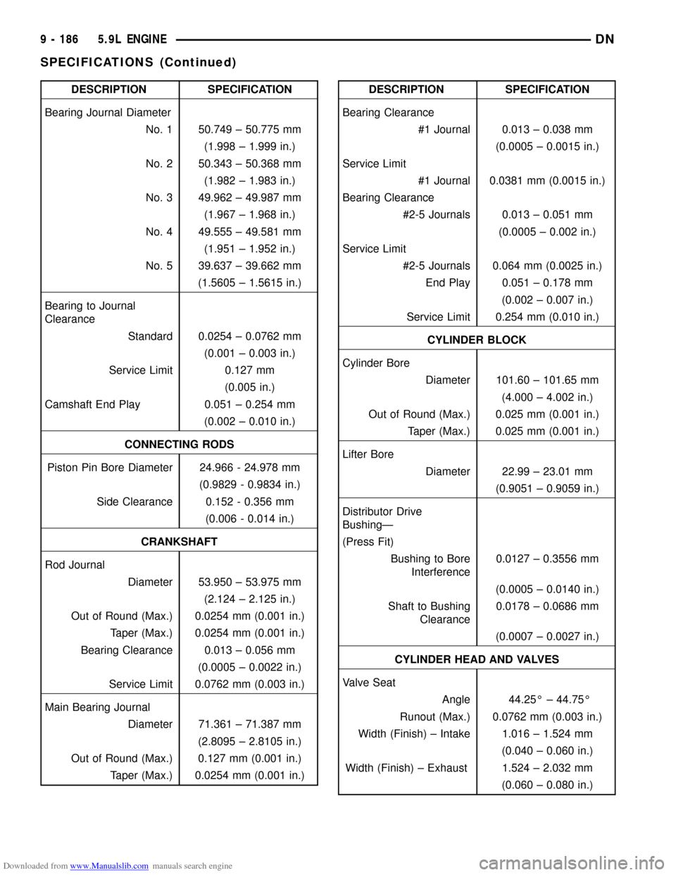
Downloaded from www.Manualslib.com manuals search engine DESCRIPTION SPECIFICATION
Bearing Journal Diameter
No. 1 50.749 ± 50.775 mm
(1.998 ± 1.999 in.)
No. 2 50.343 ± 50.368 mm
(1.982 ± 1.983 in.)
No. 3 49.962 ± 49.987 mm
(1.967 ± 1.968 in.)
No. 4 49.555 ± 49.581 mm
(1.951 ± 1.952 in.)
No. 5 39.637 ± 39.662 mm
(1.5605 ± 1.5615 in.)
Bearing to Journal
Clearance
Standard 0.0254 ± 0.0762 mm
(0.001 ± 0.003 in.)
Service Limit 0.127 mm
(0.005 in.)
Camshaft End Play 0.051 ± 0.254 mm
(0.002 ± 0.010 in.)
CONNECTING RODS
Piston Pin Bore Diameter 24.966 - 24.978 mm
(0.9829 - 0.9834 in.)
Side Clearance 0.152 - 0.356 mm
(0.006 - 0.014 in.)
CRANKSHAFT
Rod Journal
Diameter 53.950 ± 53.975 mm
(2.124 ± 2.125 in.)
Out of Round (Max.) 0.0254 mm (0.001 in.)
Taper (Max.) 0.0254 mm (0.001 in.)
Bearing Clearance 0.013 ± 0.056 mm
(0.0005 ± 0.0022 in.)
Service Limit 0.0762 mm (0.003 in.)
Main Bearing Journal
Diameter 71.361 ± 71.387 mm
(2.8095 ± 2.8105 in.)
Out of Round (Max.) 0.127 mm (0.001 in.)
Taper (Max.) 0.0254 mm (0.001 in.)DESCRIPTION SPECIFICATION
Bearing Clearance
#1 Journal 0.013 ± 0.038 mm
(0.0005 ± 0.0015 in.)
Service Limit
#1 Journal 0.0381 mm (0.0015 in.)
Bearing Clearance
#2-5 Journals 0.013 ± 0.051 mm
(0.0005 ± 0.002 in.)
Service Limit
#2-5 Journals 0.064 mm (0.0025 in.)
End Play 0.051 ± 0.178 mm
(0.002 ± 0.007 in.)
Service Limit 0.254 mm (0.010 in.)
CYLINDER BLOCK
Cylinder Bore
Diameter 101.60 ± 101.65 mm
(4.000 ± 4.002 in.)
Out of Round (Max.) 0.025 mm (0.001 in.)
Taper (Max.) 0.025 mm (0.001 in.)
Lifter Bore
Diameter 22.99 ± 23.01 mm
(0.9051 ± 0.9059 in.)
Distributor Drive
BushingÐ
(Press Fit)
Bushing to Bore
Interference0.0127 ± 0.3556 mm
(0.0005 ± 0.0140 in.)
Shaft to Bushing
Clearance0.0178 ± 0.0686 mm
(0.0007 ± 0.0027 in.)
CYLINDER HEAD AND VALVES
Valve Seat
Angle 44.25É ± 44.75É
Runout (Max.) 0.0762 mm (0.003 in.)
Width (Finish) ± Intake 1.016 ± 1.524 mm
(0.040 ± 0.060 in.)
Width (Finish) ± Exhaust 1.524 ± 2.032 mm
(0.060 ± 0.080 in.)
9 - 186 5.9L ENGINEDN
SPECIFICATIONS (Continued)
Page 188 of 193
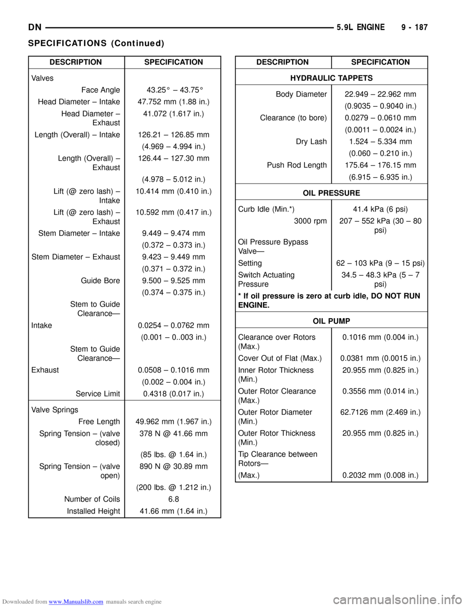
Downloaded from www.Manualslib.com manuals search engine DESCRIPTION SPECIFICATION
Valves
Face Angle 43.25É ± 43.75É
Head Diameter ± Intake 47.752 mm (1.88 in.)
Head Diameter ±
Exhaust41.072 (1.617 in.)
Length (Overall) ± Intake 126.21 ± 126.85 mm
(4.969 ± 4.994 in.)
Length (Overall) ±
Exhaust126.44 ± 127.30 mm
(4.978 ± 5.012 in.)
Lift (@ zero lash) ±
Intake10.414 mm (0.410 in.)
Lift (@ zero lash) ±
Exhaust10.592 mm (0.417 in.)
Stem Diameter ± Intake 9.449 ± 9.474 mm
(0.372 ± 0.373 in.)
Stem Diameter ± Exhaust 9.423 ± 9.449 mm
(0.371 ± 0.372 in.)
Guide Bore 9.500 ± 9.525 mm
(0.374 ± 0.375 in.)
Stem to Guide
ClearanceÐ
Intake 0.0254 ± 0.0762 mm
(0.001 ± 0..003 in.)
Stem to Guide
ClearanceÐ
Exhaust 0.0508 ± 0.1016 mm
(0.002 ± 0.004 in.)
Service Limit 0.4318 (0.017 in.)
Valve Springs
Free Length 49.962 mm (1.967 in.)
Spring Tension ± (valve
closed)378 N @ 41.66 mm
(85 lbs. @ 1.64 in.)
Spring Tension ± (valve
open)890 N @ 30.89 mm
(200 lbs. @ 1.212 in.)
Number of Coils 6.8
Installed Height 41.66 mm (1.64 in.)DESCRIPTION SPECIFICATION
HYDRAULIC TAPPETS
Body Diameter 22.949 ± 22.962 mm
(0.9035 ± 0.9040 in.)
Clearance (to bore) 0.0279 ± 0.0610 mm
(0.0011 ± 0.0024 in.)
Dry Lash 1.524 ± 5.334 mm
(0.060 ± 0.210 in.)
Push Rod Length 175.64 ± 176.15 mm
(6.915 ± 6.935 in.)
OIL PRESSURE
Curb Idle (Min.*) 41.4 kPa (6 psi)
3000 rpm 207 ± 552 kPa (30 ± 80
psi)
Oil Pressure Bypass
ValveÐ
Setting 62 ± 103 kPa (9 ± 15 psi)
Switch Actuating
Pressure34.5 ± 48.3 kPa (5 ± 7
psi)
* If oil pressure is zero at curb idle, DO NOT RUN
ENGINE.
OIL PUMP
Clearance over Rotors
(Max.)0.1016 mm (0.004 in.)
Cover Out of Flat (Max.) 0.0381 mm (0.0015 in.)
Inner Rotor Thickness
(Min.)20.955 mm (0.825 in.)
Outer Rotor Clearance
(Max.)0.3556 mm (0.014 in.)
Outer Rotor Diameter
(Min.)62.7126 mm (2.469 in.)
Outer Rotor Thickness
(Min.)20.955 mm (0.825 in.)
Tip Clearance between
RotorsÐ
(Max.) 0.2032 mm (0.008 in.)
DN5.9L ENGINE 9 - 187
SPECIFICATIONS (Continued)
Page 189 of 193
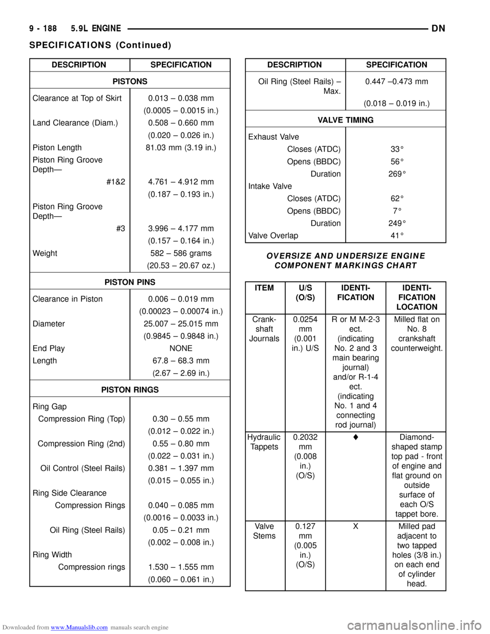
Downloaded from www.Manualslib.com manuals search engine DESCRIPTION SPECIFICATION
PISTONS
Clearance at Top of Skirt 0.013 ± 0.038 mm
(0.0005 ± 0.0015 in.)
Land Clearance (Diam.) 0.508 ± 0.660 mm
(0.020 ± 0.026 in.)
Piston Length 81.03 mm (3.19 in.)
Piston Ring Groove
DepthÐ
#1&2 4.761 ± 4.912 mm
(0.187 ± 0.193 in.)
Piston Ring Groove
DepthÐ
#3 3.996 ± 4.177 mm
(0.157 ± 0.164 in.)
Weight 582 ± 586 grams
(20.53 ± 20.67 oz.)
PISTON PINS
Clearance in Piston 0.006 ± 0.019 mm
(0.00023 ± 0.00074 in.)
Diameter 25.007 ± 25.015 mm
(0.9845 ± 0.9848 in.)
End Play NONE
Length 67.8 ± 68.3 mm
(2.67 ± 2.69 in.)
PISTON RINGS
Ring Gap
Compression Ring (Top) 0.30 ± 0.55 mm
(0.012 ± 0.022 in.)
Compression Ring (2nd) 0.55 ± 0.80 mm
(0.022 ± 0.031 in.)
Oil Control (Steel Rails) 0.381 ± 1.397 mm
(0.015 ± 0.055 in.)
Ring Side Clearance
Compression Rings 0.040 ± 0.085 mm
(0.0016 ± 0.0033 in.)
Oil Ring (Steel Rails) 0.05 ± 0.21 mm
(0.002 ± 0.008 in.)
Ring Width
Compression rings 1.530 ± 1.555 mm
(0.060 ± 0.061 in.)DESCRIPTION SPECIFICATION
Oil Ring (Steel Rails) ±
Max.0.447 ±0.473 mm
(0.018 ± 0.019 in.)
VALVE TIMING
Exhaust Valve
Closes (ATDC) 33É
Opens (BBDC) 56É
Duration 269É
Intake Valve
Closes (ATDC) 62É
Opens (BBDC) 7É
Duration 249É
Valve Overlap 41É
OVERSIZE AND UNDERSIZE ENGINE
COMPONENT MARKINGS CHART
ITEM U/S
(O/S)IDENTI-
FICATIONIDENTI-
FICATION
LOCATION
Crank-
shaft
Journals0.0254
mm
(0.001
in.) U/SR or M M-2-3
ect.
(indicating
No. 2 and 3
main bearing
journal)
and/or R-1-4
ect.
(indicating
No. 1 and 4
connecting
rod journal)Milled flat on
No. 8
crankshaft
counterweight.
Hydraulic
Tappets0.2032
mm
(0.008
in.)
(O/S)lDiamond-
shaped stamp
top pad - front
of engine and
flat ground on
outside
surface of
each O/S
tappet bore.
Valve
Stems0.127
mm
(0.005
in.)
(O/S)X Milled pad
adjacent to
two tapped
holes (3/8 in.)
on each end
of cylinder
head.
9 - 188 5.9L ENGINEDN
SPECIFICATIONS (Continued)
Page 190 of 193
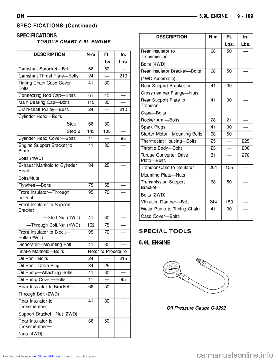
Downloaded from www.Manualslib.com manuals search engine SPECIFICATIONS
TORQUE CHART 5.9L ENGINE
DESCRIPTION N´m Ft. In.
Lbs. Lbs.
Camshaft SprocketÐBolt 68 50 Ð
Camshaft Thrust PlateÐBolts 24 Ð 210
Timing Chain Case CoverÐ
Bolts41 30 Ð
Connecting Rod CapÐBolts 61 45 Ð
Main Bearing CapÐBolts 115 85 Ð
Crankshaft PulleyÐBolts 24 Ð 210
Cylinder HeadÐBolts
Step 1 68 50 Ð
Step 2 143 105 Ð
Cylinder Head CoverÐBolts 11 Ð 95
Engine Support Bracket to
BlockÐ41 30 Ð
Bolts (4WD)
Exhaust Manifold to Cylinder
HeadÐ34 25 Ð
Bolts/Nuts
FlywheelÐBolts 75 55 Ð
Front InsulatorÐThrough
bolt/nut95 70 Ð
Front Insulator to Support
Bracket
ÐStud Nut (4WD) 41 30 Ð
ÐThrough Bolt/Nut (4WD) 102 75 Ð
Front Insulator to BlockÐ
Bolts (2WD)95 70 Ð
GeneratorÐMounting Bolt 41 30 Ð
Intake ManifoldÐBolts Refer to Procedure
Oil PanÐBolts 24 Ð 215
Oil PanÐDrain Plug 34 25 Ð
Oil PumpÐAttaching Bolts 41 30 Ð
Oil Pump CoverÐBolts 11 Ð 95
Rear Insulator to BracketÐ 68 50 Ð
Through-Bolt (2WD)
Rear Insulator to
Crossmember41 30 Ð
Support BracketÐNut (2WD)
Rear Insulator to
CrossmemberÐ68 50 Ð
Nuts (4WD)
DESCRIPTION N´m Ft. In.
Lbs. Lbs.
Rear Insulator to
TransmissionÐ68 50 Ð
Bolts (4WD)
Rear Insulator BracketÐBolts 68 50 Ð
(4WD Automatic)
Rear Support Bracket to 41 30 Ð
Crossmember FlangeÐNuts
Rear Support Plate to
Transfer41 30 Ð
CaseÐBolts
Rocker ArmÐBolts 28 21 Ð
Spark Plugs 41 30 Ð
Starter MotorÐMounting Bolts 68 50 Ð
Thermostat HousingÐBolts 25 Ð 225
Throttle BodyÐBolts 23 Ð 200
Torque Converter Drive
PlateÐBolts31 Ð 270
Transfer Case to Insulator 204 105 Ð
Mounting PlateÐNuts
Transmission Support
BracketÐ68 50 Ð
Bolts (2WD)
Vibration DamperÐBolt 244 180 Ð
Water Pump to Timing Chain 41 30 Ð
Case CoverÐBolts
SPECIAL TOOLS
5.9L ENGINE
Oil Pressure Gauge C-3292
DN5.9L ENGINE 9 - 189
SPECIFICATIONS (Continued)
Page 191 of 193
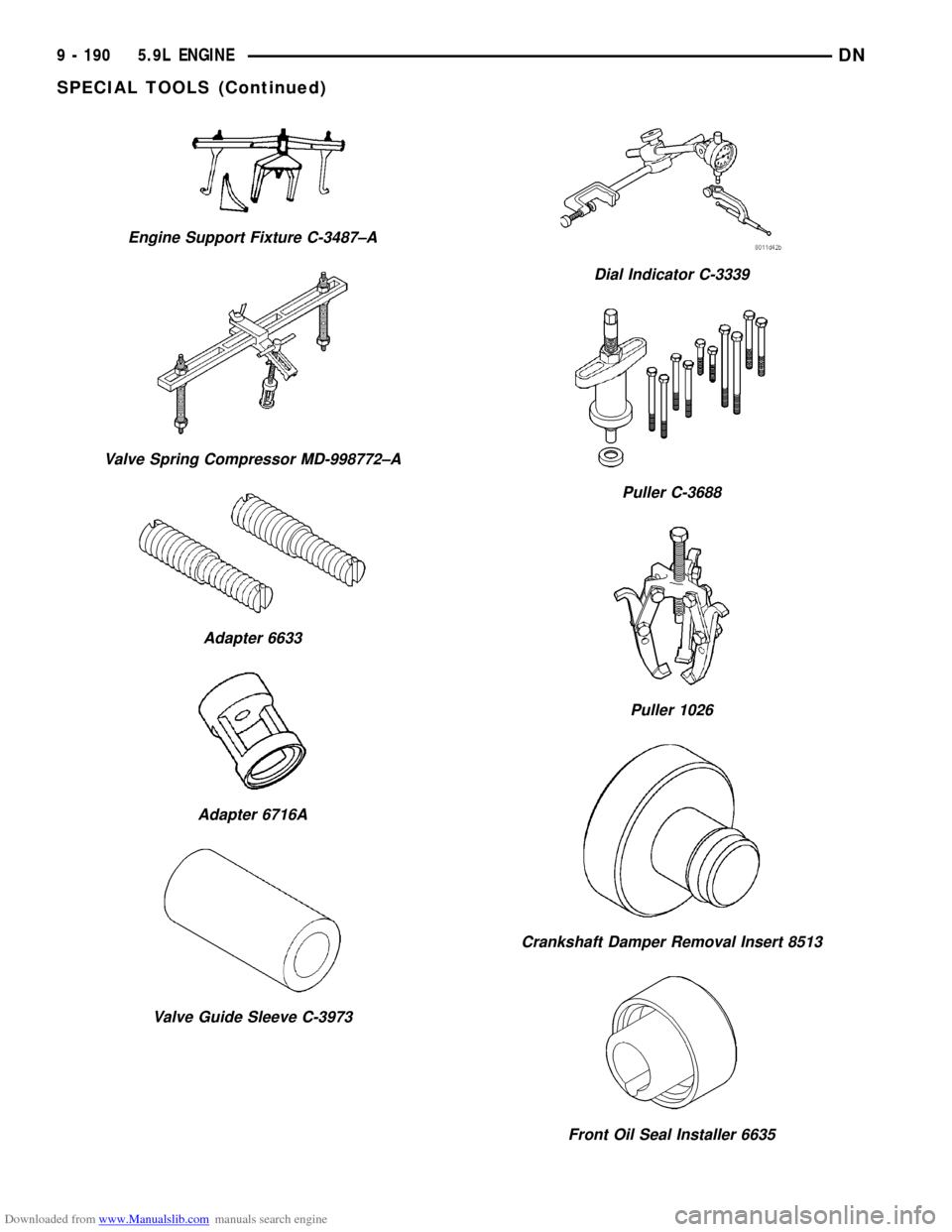
Downloaded from www.Manualslib.com manuals search engine Engine Support Fixture C-3487±A
Valve Spring Compressor MD-998772±A
Adapter 6633
Adapter 6716A
Valve Guide Sleeve C-3973
Dial Indicator C-3339
Puller C-3688
Puller 1026
Crankshaft Damper Removal Insert 8513
Front Oil Seal Installer 6635
9 - 190 5.9L ENGINEDN
SPECIAL TOOLS (Continued)
Page 192 of 193
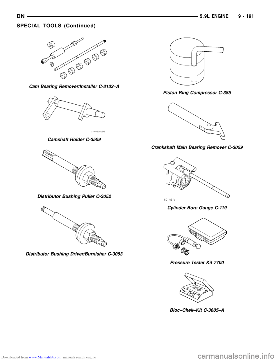
Downloaded from www.Manualslib.com manuals search engine Cam Bearing Remover/Installer C-3132±A
Camshaft Holder C-3509
Distributor Bushing Puller C-3052
Distributor Bushing Driver/Burnisher C-3053
Piston Ring Compressor C-385
Crankshaft Main Bearing Remover C-3059
Cylinder Bore Gauge C-119
Pressure Tester Kit 7700
Bloc±Chek±Kit C-3685±A
DN5.9L ENGINE 9 - 191
SPECIAL TOOLS (Continued)