Crank sensor DODGE DURANGO 1999 1.G Workshop Manual
[x] Cancel search | Manufacturer: DODGE, Model Year: 1999, Model line: DURANGO, Model: DODGE DURANGO 1999 1.GPages: 193, PDF Size: 5.65 MB
Page 4 of 193
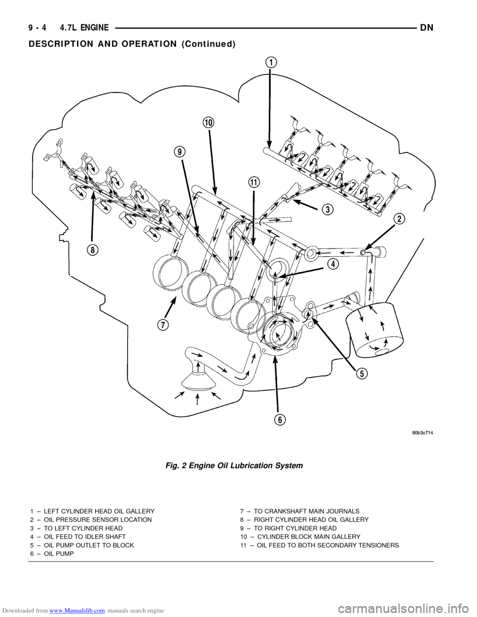
Downloaded from www.Manualslib.com manuals search engine 1 ± LEFT CYLINDER HEAD OIL GALLERY
2 ± OIL PRESSURE SENSOR LOCATION
3 ± TO LEFT CYLINDER HEAD
4 ± OIL FEED TO IDLER SHAFT
5 ± OIL PUMP OUTLET TO BLOCK
6 ± OIL PUMP7 ± TO CRANKSHAFT MAIN JOURNALS
8 ± RIGHT CYLINDER HEAD OIL GALLERY
9 ± TO RIGHT CYLINDER HEAD
10 ± CYLINDER BLOCK MAIN GALLERY
11 ± OIL FEED TO BOTH SECONDARY TENSIONERS
Fig. 2 Engine Oil Lubrication System
9 - 4 4.7L ENGINEDN
DESCRIPTION AND OPERATION (Continued)
Page 5 of 193
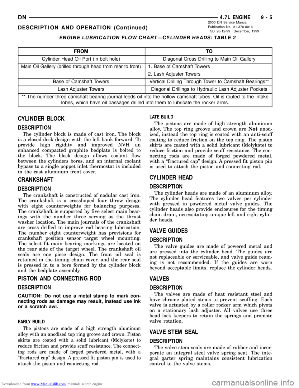
Downloaded from www.Manualslib.com manuals search engine ENGINE LUBRICATION FLOW CHARTÐCYLINDER HEADS: TABLE 2
FROM TO
Cylinder Head Oil Port (in bolt hole) Diagonal Cross Drilling to Main Oil Gallery
Main Oil Gallery (drilled through head from rear to front)1. Base of Camshaft Towers
2. Lash Adjuster Towers
Base of Camshaft Towers Vertical Drilling Through Tower to Camshaft Bearings**
Lash Adjuster Towers Diagonal Drillings to Hydraulic Lash Adjuster Pockets
** The number three camshaft bearing journal feeds oil into the hollow camshaft tubes. Oil is routed to the intake
lobes, which have oil passages drilled into them to lubricate the rocker arms.
CYLINDER BLOCK
DESCRIPTION
The cylinder block is made of cast iron. The block
is a closed deck design with the left bank forward. To
provide high rigidity and improved NVH an
enhanced compacted graphite bedplate is bolted to
the block. The block design allows coolant flow
between the cylinders bores, and an internal coolant
bypass to a single poppet inlet thermostat is included
in the cast aluminum front cover.
CRANKSHAFT
DESCRIPTION
The crankshaft is constructed of nodular cast iron.
The crankshaft is a crosshaped four throw design
with eight counterweights for balancing purposes.
The crankshaft is supported by five select main bear-
ings with the number three serving as the thrust
washer location. The main journals of the crankshaft
are cross drilled to improve rod bearing lubrication.
The number eight counterweight has provisions for
crankshaft position sensor target wheel mounting.
The select fit main bearing markings are located on
the rear side of the target wheel. The crankshaft oil
seals are one piece design. The front oil seal is
retained in the timing chain cover, and the rear seal
is pressed in to a bore formed by the cylinder block
and the bedplate assembly.
PISTON AND CONNECTING ROD
DESCRIPTION
CAUTION: Do not use a metal stamp to mark con-
necting rods as damage may result, instead use ink
or a scratch awl.
EARLY BUILD
The pistons are made of a high strength aluminum
alloy with an anodized top ring groove and crown. Piston
skirts are coated with a solid lubricant (Molykote) to
reduce friction and provide scuff resistance. The connect-
ing rods are made of forged powdered metal, with a
ªfractured capº design. A pressed fit piston pin is used to
attach the piston and connecting rod.
LATE BUILD
The pistons are made of high strength aluminum
alloy. The top ring groove and crown areNotanod-
ized, instead the top ring is coated with an anti-scuff
coating to reduce friction on the top ring. The piston
skirts are coated with a solid lubricant (Molykote) to
reduce friction and provide scuff resistance. The con-
necting rods are made of forged powdered metal,
with a ªfractured capº design. A pressed fit piston pin
is used to attach the piston and connecting rod.
CYLINDER HEAD
DESCRIPTION
The cylinder heads are made of an aluminum alloy.
The cylinder head features two valves per cylinder
with pressed in powdered metal valve guides. The
cylinder heads also provide enclosures for the timing
chain drain, necessitating unique left and right cylin-
der heads.
VALVE GUIDES
DESCRIPTION
The valve guides are made of powered metal and
are pressed into the cylinder head. The guides are
not replaceable or serviceable, and valve guide ream-
ing is not recommended. If the guides are worn
beyond acceptable limits, replace the cylinder heads.
VALVES
DESCRIPTION
The valves are made of heat resistant steel and
have chrome plated stems to prevent scuffing. Each
valve is actuated by a roller rocker arm which pivots
on a stationary lash adjuster. All valves use three
bead lock keepers to retain the springs and promote
valve rotation.
VALVE STEM SEAL
DESCRIPTION
The valve stem seals are made of rubber and incor-
porate an integral steel valve spring seat. The inte-
gral garter spring maintains consistent lubrication
control to the valve stems.
DN4.7L ENGINE 9 - 5
DESCRIPTION AND OPERATION (Continued)
2000 DN Service Manual
Publication No. 81-370-0016
TSB 26-12-99 December, 1999
Page 31 of 193
Downloaded from www.Manualslib.com manuals search engine ENGINE ASSEMBLY
REMOVAL
NOTE: This procedure applies to both the 4X2 and
4X4 vehicles, steps that apply to the 4X4 vehicle
only, are identified.
(1) Disconnect the battery negative and positive
cables.
(2) Remove the battery and the battery tray. Refer
to BATTERY.
(3) Raise vehicle on hoist.
(4) Remove exhaust crossover pipe from exhaust
manifolds. Refer to EXHAUST SYSTEM.
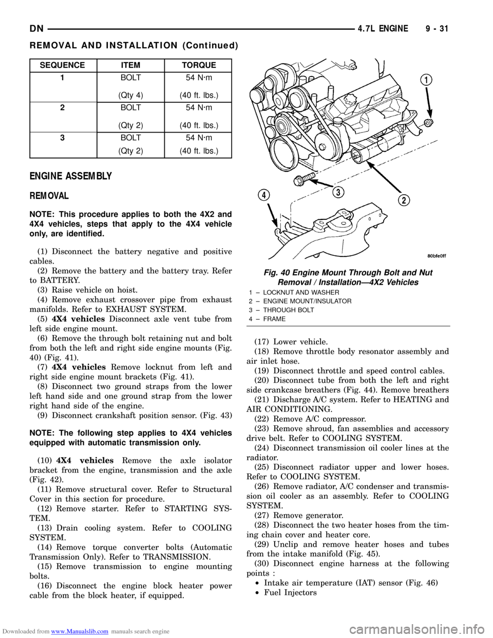
(5)4X4 vehiclesDisconnect axle vent tube from
left side engine mount.
(6) Remove the through bolt retaining nut and bolt
from both the left and right side engine mounts (Fig.
40) (Fig. 41).
(7)4X4 vehiclesRemove locknut from left and
right side engine mount brackets (Fig. 41).
(8) Disconnect two ground straps from the lower
left hand side and one ground strap from the lower
right hand side of the engine.
(9) Disconnect crankshaft position sensor. (Fig. 43)
NOTE: The following step applies to 4X4 vehicles
equipped with automatic transmission only.
(10)4X4 vehiclesRemove the axle isolator
bracket from the engine, transmission and the axle
(Fig. 42).
(11) Remove structural cover. Refer to Structural
Cover in this section for procedure.
(12) Remove starter. Refer to STARTING SYS-
TEM.
(13) Drain cooling system. Refer to COOLING
SYSTEM.
(14) Remove torque converter bolts (Automatic
Transmission Only). Refer to TRANSMISSION.
(15) Remove transmission to engine mounting
bolts.
(16) Disconnect the engine block heater power
cable from the block heater, if equipped.(17) Lower vehicle.
(18) Remove throttle body resonator assembly and
air inlet hose.
(19) Disconnect throttle and speed control cables.
(20) Disconnect tube from both the left and right
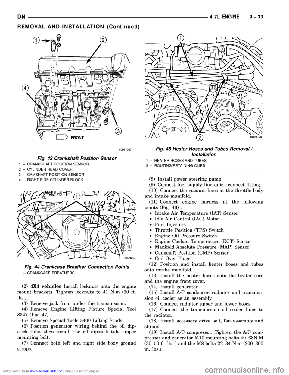
side crankcase breathers (Fig. 44). Remove breathers
(21) Discharge A/C system. Refer to HEATING and
AIR CONDITIONING.
(22) Remove A/C compressor.
(23) Remove shroud, fan assemblies and accessory
drive belt. Refer to COOLING SYSTEM.
(24) Disconnect transmission oil cooler lines at the
radiator.
(25) Disconnect radiator upper and lower hoses.
Refer to COOLING SYSTEM.
(26) Remove radiator, A/C condenser and transmis-
sion oil cooler as an assembly. Refer to COOLING
SYSTEM.
(27) Remove generator.
(28) Disconnect the two heater hoses from the tim-
ing chain cover and heater core.
(29) Unclip and remove heater hoses and tubes
from the intake manifold (Fig. 45).
(30) Disconnect engine harness at the following
points :
²Intake air temperature (IAT) sensor (Fig. 46)
²Fuel Injectors
SEQUENCE ITEM TORQUE
1BOLT 54 N´m
(Qty 4) (40 ft. lbs.)
2BOLT 54 N´m
(Qty 2) (40 ft. lbs.)
3BOLT 54 N´m
(Qty 2) (40 ft. lbs.)
Fig. 40 Engine Mount Through Bolt and Nut
Removal / InstallationÐ4X2 Vehicles
1 ± LOCKNUT AND WASHER
2 ± ENGINE MOUNT/INSULATOR
3 ± THROUGH BOLT
4 ± FRAME
DN4.7L ENGINE 9 - 31
REMOVAL AND INSTALLATION (Continued)
Page 33 of 193
Downloaded from www.Manualslib.com manuals search engine (2)4X4 vehiclesInstall locknuts onto the engine
mount brackets. Tighten locknuts to 41 N´m (30 ft.
lbs.).
(3) Remove jack from under the transmission.
(4) Remove Engine Lifting Fixture Special Tool
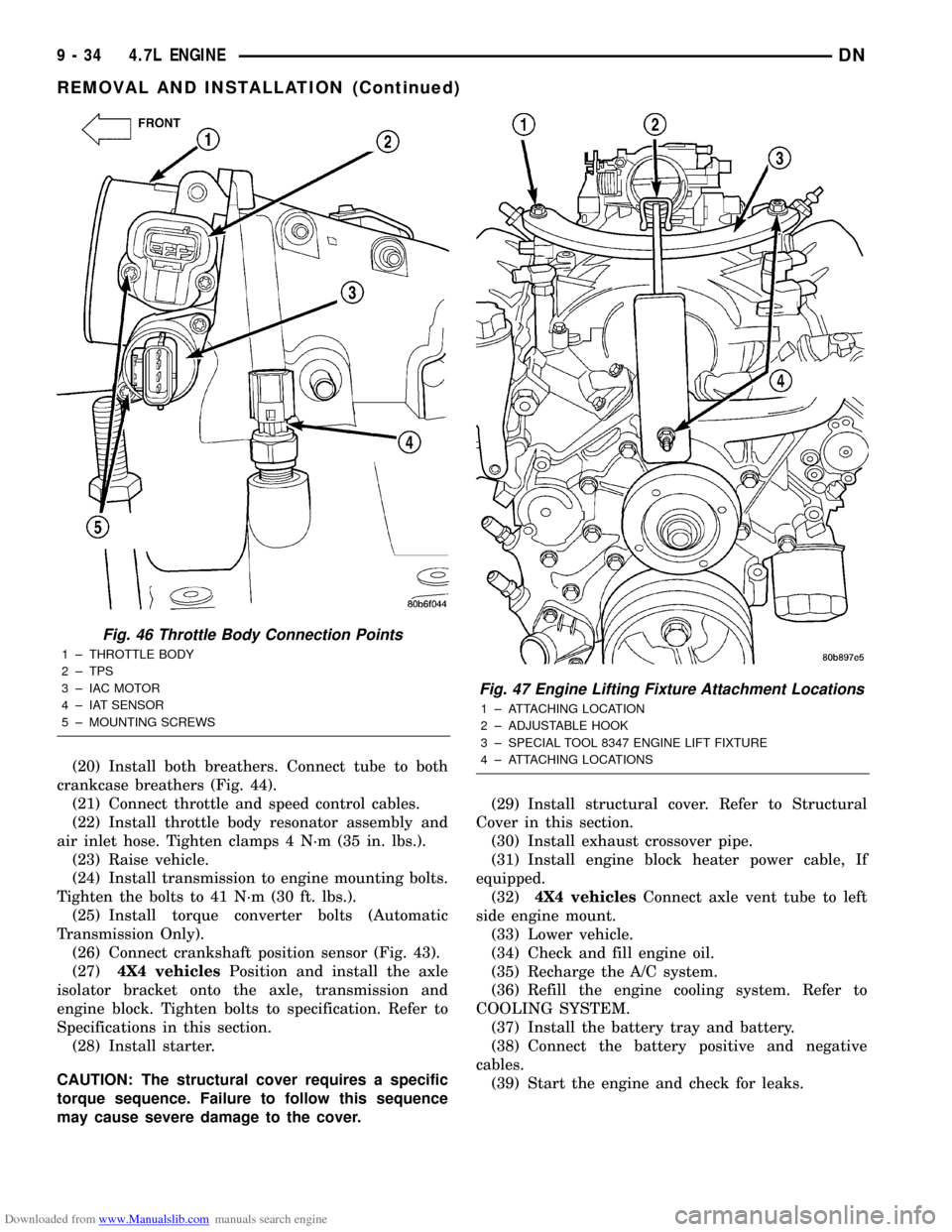
8347 (Fig. 47).
(5) Remove Special Tools 8400 Lifting Studs.
(6) Position generator wiring behind the oil dip-
stick tube, then install the oil dipstick tube upper
mounting bolt.
(7) Connect both left and right side body ground
straps.(8) Install power steering pump.
(9) Connect fuel supply line quick connect fitting.
(10) Connect the vacuum lines at the throttle body
and intake manifold.
(11) Connect engine harness at the following
points (Fig. 46) :
²Intake Air Temperature (IAT) Sensor
²Idle Air Control (IAC) Motor
²Fuel Injectors
²Throttle Position (TPS) Switch
²Engine Oil Pressure Switch
²Engine Coolant Temperature (ECT) Sensor
²Manifold Absolute Pressure (MAP) Sensor
²Camshaft Position (CMP) Sensor
²Coil Over Plugs
(12) Position and install heater hoses and tubes
onto intake manifold.
(13) Install the heater hoses onto the heater core
and the engine front cover.
(14) Install generator.
(15) Install A/C condenser, radiator and transmis-
sion oil cooler as an assembly.
(16) Connect radiator upper and lower hoses.
(17) Connect the transmission oil cooler lines to
the radiator.
(18) Install accessory drive belt, fan assembly and
shroud.
(19) Install A/C compressor. Tighten the A/C com-
pressor and generator M10 mounting bolts 40±68N´M
(30±50 ft. lbs.) and the M8 bolts 22±34 N´m (200±300
in. lbs.).
Fig. 43 Crankshaft Position Sensor
1 ± CRANKSHAFT POSITION SENSOR
2 ± CYLINDER HEAD COVER
3 ± CAMSHAFT POSITION SENSOR
4 ± RIGHT SIDE CYLINDER BLOCK
Fig. 44 Crankcase Breather Connection Points
1 ± CRANKCASE BREATHERS
Fig. 45 Heater Hoses and Tubes Removal /
Installation
1 ± HEATER HOSES AND TUBES
2 ± ROUTING/RETAINING CLIPS
DN4.7L ENGINE 9 - 33
REMOVAL AND INSTALLATION (Continued)
Page 34 of 193
Downloaded from www.Manualslib.com manuals search engine (20) Install both breathers. Connect tube to both
crankcase breathers (Fig. 44).
(21) Connect throttle and speed control cables.
(22) Install throttle body resonator assembly and
air inlet hose. Tighten clamps 4 N´m (35 in. lbs.).
(23) Raise vehicle.
(24) Install transmission to engine mounting bolts.
Tighten the bolts to 41 N´m (30 ft. lbs.).
(25) Install torque converter bolts (Automatic
Transmission Only).
(26) Connect crankshaft position sensor (Fig. 43).
(27)4X4 vehiclesPosition and install the axle
isolator bracket onto the axle, transmission and
engine block. Tighten bolts to specification. Refer to
Specifications in this section.
(28) Install starter.
CAUTION: The structural cover requires a specific
torque sequence. Failure to follow this sequence
may cause severe damage to the cover.(29) Install structural cover. Refer to Structural
Cover in this section.
(30) Install exhaust crossover pipe.
(31) Install engine block heater power cable, If
equipped.
(32)4X4 vehiclesConnect axle vent tube to left
side engine mount.
(33) Lower vehicle.
(34) Check and fill engine oil.
(35) Recharge the A/C system.
(36) Refill the engine cooling system. Refer to
COOLING SYSTEM.
(37) Install the battery tray and battery.
(38) Connect the battery positive and negative
cables.
(39) Start the engine and check for leaks.
Fig. 46 Throttle Body Connection Points
1 ± THROTTLE BODY
2 ± TPS
3 ± IAC MOTOR
4 ± IAT SENSOR
5 ± MOUNTING SCREWS
Fig. 47 Engine Lifting Fixture Attachment Locations
1 ± ATTACHING LOCATION
2 ± ADJUSTABLE HOOK
3 ± SPECIAL TOOL 8347 ENGINE LIFT FIXTURE
4 ± ATTACHING LOCATIONS
9 - 34 4.7L ENGINEDN
REMOVAL AND INSTALLATION (Continued)
Page 35 of 193
Downloaded from www.Manualslib.com manuals search engine INTAKE MANIFOLD
REMOVAL
(1) Disconnect negative cable from battery.
(2) Remove resonator assembly and air inlet hose.
(3) Disconnect throttle and speed control cables.
(4) Disconnect electrical connectors for the follow-
ing components: Refer to FUEL SYSTEM for compo-
nent locations.
²Manifold Absolute Pressure (MAP) Sensor
²Intake Air Temperature (IAT) Sensor
²Throttle Position (TPS) Sensor
²Coolant Temperature (CTS) Sensor
²Idle Air Control (IAC) Motor
(5) Disconnect vapor purge hose, brake booster
hose, speed control servo hose, positive crankcase
ventilation (PCV) hose.
(6) Disconnect generator electrical connections.
(7) Disconnect air conditioning compressor electri-
cal connections.
(8) Disconnect left and right radio suppressor
straps.
(9) Disconnect and remove ignition coil towers.
(10) Remove top oil dipstick tube retaining bolt
and ground strap.
(11) Bleed fuel system. Refer to FUEL SYSTEM.
(12) Remove fuel rail.
(13) Remove throttle body assembly and mounting
bracket.
(14) Drain cooling system below coolant tempera-
ture level. Refer to COOLING SYSTEM.
(15) Remove the heater hoses from the engine
front cover and the heater core.
(16) Unclip and remove heater hoses and tubes
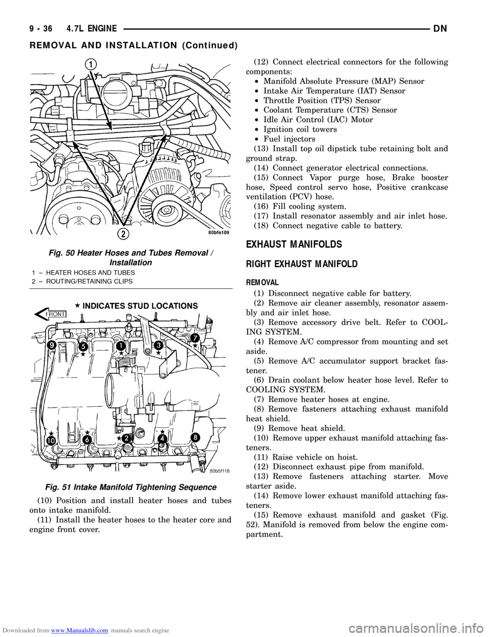
from intake manifold (Fig. 50).
(17) Remove coolant temperature sensor. Refer to
FUEL SYSTEM.
(18) Remove intake manifold retaining fasteners in
reverse order of tightening sequence (Fig. 51).
(19) Remove intake manifold.
INSTALLATION
(1) Install intake manifold gaskets.
(2) Install intake manifold.
(3) Install intake manifold retaining bolts and
tighten in sequence shown in (Fig. 51) to 12 N´m
(105 in. lbs.).
(4) Install left and right radio suppressor straps.
(5) Install throttle body assembly.
(6) Install throttle cable bracket.
(7) Connect throttle cable and speed control cable
to throttle body.
(8) Install fuel rail.
(9) Install ignition coil towers.
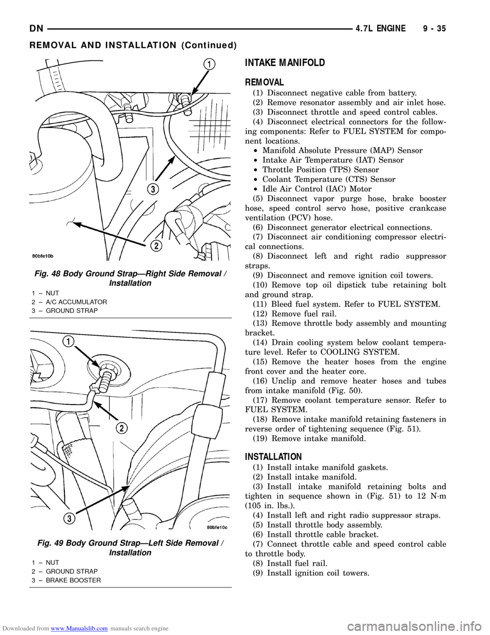
Fig. 48 Body Ground StrapÐRight Side Removal /
Installation
1 ± NUT
2 ± A/C ACCUMULATOR
3 ± GROUND STRAP
Fig. 49 Body Ground StrapÐLeft Side Removal /
Installation
1 ± NUT
2 ± GROUND STRAP
3 ± BRAKE BOOSTER
DN4.7L ENGINE 9 - 35
REMOVAL AND INSTALLATION (Continued)
Page 36 of 193
Downloaded from www.Manualslib.com manuals search engine (10) Position and install heater hoses and tubes
onto intake manifold.
(11) Install the heater hoses to the heater core and
engine front cover.(12) Connect electrical connectors for the following
components:
²Manifold Absolute Pressure (MAP) Sensor
²Intake Air Temperature (IAT) Sensor
²Throttle Position (TPS) Sensor
²Coolant Temperature (CTS) Sensor
²Idle Air Control (IAC) Motor
²Ignition coil towers
²Fuel injectors
(13) Install top oil dipstick tube retaining bolt and
ground strap.
(14) Connect generator electrical connections.
(15) Connect Vapor purge hose, Brake booster
hose, Speed control servo hose, Positive crankcase
ventilation (PCV) hose.
(16) Fill cooling system.
(17) Install resonator assembly and air inlet hose.
(18) Connect negative cable to battery.
EXHAUST MANIFOLDS
RIGHT EXHAUST MANIFOLD
REMOVAL
(1) Disconnect negative cable for battery.
(2) Remove air cleaner assembly, resonator assem-
bly and air inlet hose.
(3) Remove accessory drive belt. Refer to COOL-
ING SYSTEM.
(4) Remove A/C compressor from mounting and set
aside.
(5) Remove A/C accumulator support bracket fas-
tener.
(6) Drain coolant below heater hose level. Refer to
COOLING SYSTEM.
(7) Remove heater hoses at engine.
(8) Remove fasteners attaching exhaust manifold
heat shield.
(9) Remove heat shield.
(10) Remove upper exhaust manifold attaching fas-
teners.
(11) Raise vehicle on hoist.
(12) Disconnect exhaust pipe from manifold.
(13) Remove fasteners attaching starter. Move
starter aside.
(14) Remove lower exhaust manifold attaching fas-
teners.
(15) Remove exhaust manifold and gasket (Fig.
52). Manifold is removed from below the engine com-
partment.
Fig. 50 Heater Hoses and Tubes Removal /
Installation
1 ± HEATER HOSES AND TUBES
2 ± ROUTING/RETAINING CLIPS
Fig. 51 Intake Manifold Tightening Sequence
9 - 36 4.7L ENGINEDN
REMOVAL AND INSTALLATION (Continued)
Page 51 of 193
Downloaded from www.Manualslib.com manuals search engine CAUTION: Care should be taken not to damage
camshaft target wheel. Do not hold target wheel
while loosening or tightening camshaft sprocket.
Do not place the target wheel near a magnetic
source of any kind. A damaged or magnetized tar-
get wheel could cause a vehicle no start condition.
CAUTION: Do not forcefully rotate the camshafts or
crankshaft independently of each other. Damaging
intake valve to piston contact will occur. Ensure
negative battery cable is disconnected to guard
against accidental starter engagement.
(13) Remove left and right camshaft sprocket bolts.
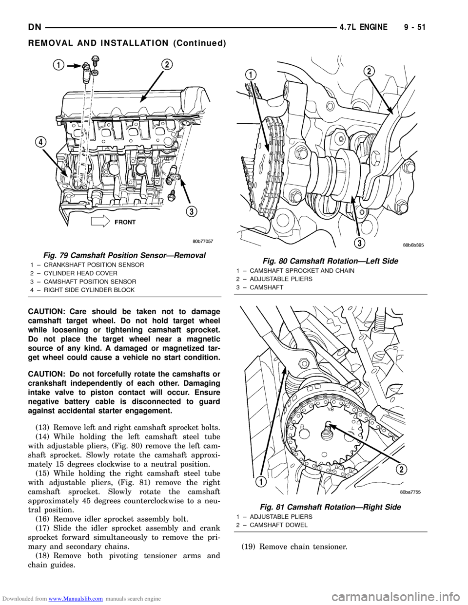
(14) While holding the left camshaft steel tube
with adjustable pliers, (Fig. 80) remove the left cam-
shaft sprocket. Slowly rotate the camshaft approxi-
mately 15 degrees clockwise to a neutral position.
(15) While holding the right camshaft steel tube
with adjustable pliers, (Fig. 81) remove the right
camshaft sprocket. Slowly rotate the camshaft
approximately 45 degrees counterclockwise to a neu-
tral position.
(16) Remove idler sprocket assembly bolt.
(17) Slide the idler sprocket assembly and crank
sprocket forward simultaneously to remove the pri-
mary and secondary chains.
(18) Remove both pivoting tensioner arms and
chain guides.(19) Remove chain tensioner.
Fig. 79 Camshaft Position SensorÐRemoval
1 ± CRANKSHAFT POSITION SENSOR
2 ± CYLINDER HEAD COVER
3 ± CAMSHAFT POSITION SENSOR
4 ± RIGHT SIDE CYLINDER BLOCKFig. 80 Camshaft RotationÐLeft Side
1 ± CAMSHAFT SPROCKET AND CHAIN
2 ± ADJUSTABLE PLIERS
3 ± CAMSHAFT
Fig. 81 Camshaft RotationÐRight Side
1 ± ADJUSTABLE PLIERS
2 ± CAMSHAFT DOWEL
DN4.7L ENGINE 9 - 51
REMOVAL AND INSTALLATION (Continued)
Page 60 of 193
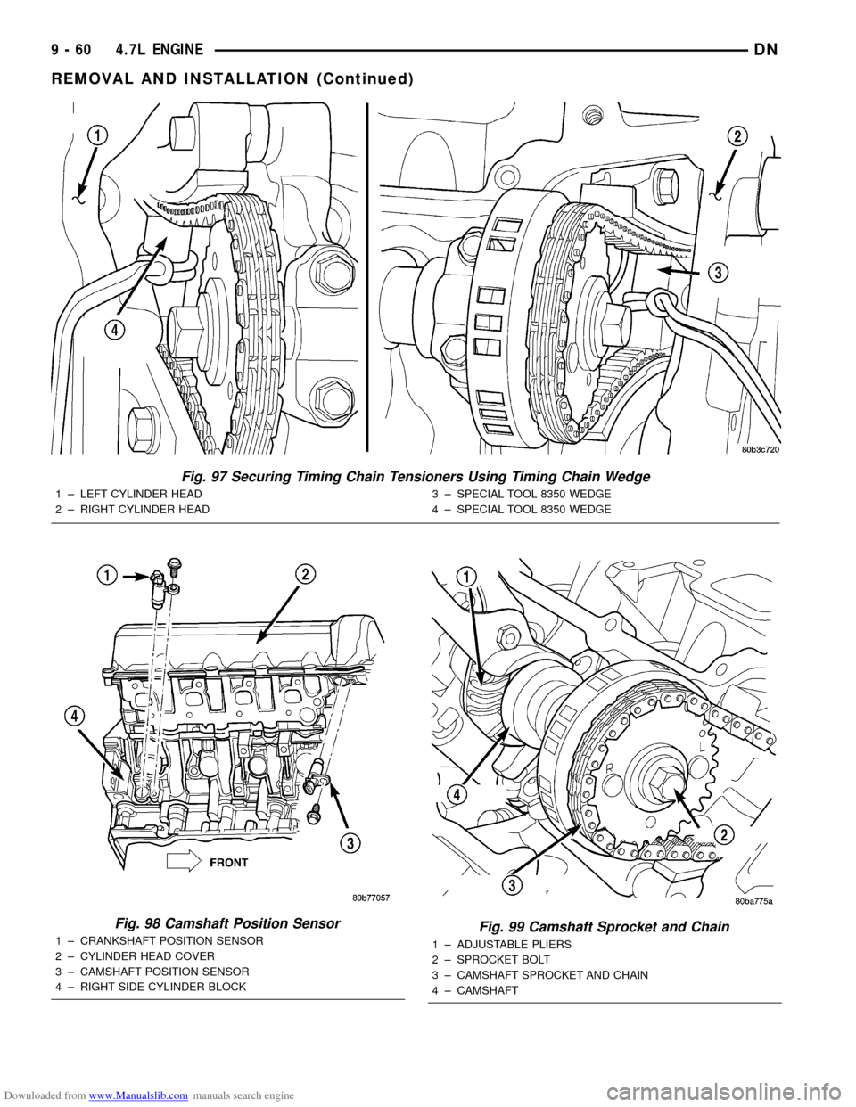
Downloaded from www.Manualslib.com manuals search engine Fig. 97 Securing Timing Chain Tensioners Using Timing Chain Wedge
1 ± LEFT CYLINDER HEAD
2 ± RIGHT CYLINDER HEAD3 ± SPECIAL TOOL 8350 WEDGE
4 ± SPECIAL TOOL 8350 WEDGE
Fig. 98 Camshaft Position Sensor
1 ± CRANKSHAFT POSITION SENSOR
2 ± CYLINDER HEAD COVER
3 ± CAMSHAFT POSITION SENSOR
4 ± RIGHT SIDE CYLINDER BLOCKFig. 99 Camshaft Sprocket and Chain
1 ± ADJUSTABLE PLIERS
2 ± SPROCKET BOLT
3 ± CAMSHAFT SPROCKET AND CHAIN
4 ± CAMSHAFT
9 - 60 4.7L ENGINEDN
REMOVAL AND INSTALLATION (Continued)
Page 61 of 193
Downloaded from www.Manualslib.com manuals search engine INSTALLATION
(1) Lubricate camshaft journals with clean engine
oil.
NOTE: Position the right side camshaft so that the
camshaft sprocket dowel is near the 10 o'clock
position, This will place the camshaft at the neutral
position easing the installation of the camshaft
bearing caps.
(2) Position the camshaft into the cylinder head.
(3) Install the camshaft bearing caps, hand tighten
the retaining bolts.
(4) Working in 1/2 turn increments, tighten the
bearing cap retaining bolts starting with the middle
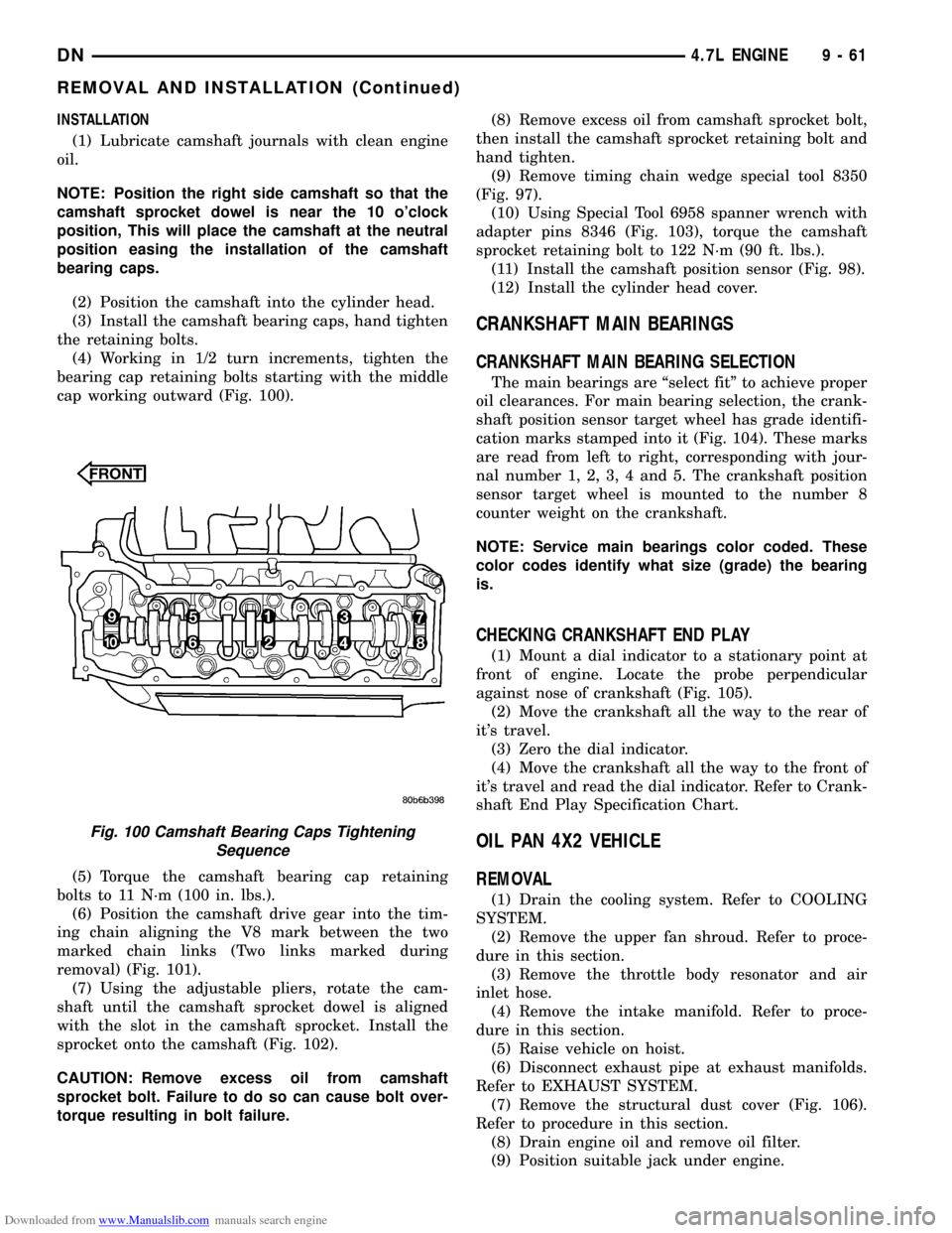
cap working outward (Fig. 100).
(5) Torque the camshaft bearing cap retaining
bolts to 11 N´m (100 in. lbs.).
(6) Position the camshaft drive gear into the tim-
ing chain aligning the V8 mark between the two
marked chain links (Two links marked during
removal) (Fig. 101).
(7) Using the adjustable pliers, rotate the cam-
shaft until the camshaft sprocket dowel is aligned
with the slot in the camshaft sprocket. Install the
sprocket onto the camshaft (Fig. 102).
CAUTION: Remove excess oil from camshaft
sprocket bolt. Failure to do so can cause bolt over-
torque resulting in bolt failure.(8) Remove excess oil from camshaft sprocket bolt,
then install the camshaft sprocket retaining bolt and
hand tighten.
(9) Remove timing chain wedge special tool 8350
(Fig. 97).
(10) Using Special Tool 6958 spanner wrench with
adapter pins 8346 (Fig. 103), torque the camshaft
sprocket retaining bolt to 122 N´m (90 ft. lbs.).
(11) Install the camshaft position sensor (Fig. 98).
(12) Install the cylinder head cover.
CRANKSHAFT MAIN BEARINGS
CRANKSHAFT MAIN BEARING SELECTION
The main bearings are ªselect fitº to achieve proper
oil clearances. For main bearing selection, the crank-
shaft position sensor target wheel has grade identifi-
cation marks stamped into it (Fig. 104). These marks
are read from left to right, corresponding with jour-
nal number 1, 2, 3, 4 and 5. The crankshaft position
sensor target wheel is mounted to the number 8
counter weight on the crankshaft.
NOTE: Service main bearings color coded. These
color codes identify what size (grade) the bearing
is.
CHECKING CRANKSHAFT END PLAY
(1) Mount a dial indicator to a stationary point at
front of engine. Locate the probe perpendicular
against nose of crankshaft (Fig. 105).
(2) Move the crankshaft all the way to the rear of
it's travel.
(3) Zero the dial indicator.
(4) Move the crankshaft all the way to the front of
it's travel and read the dial indicator. Refer to Crank-
shaft End Play Specification Chart.
OIL PAN 4X2 VEHICLE
REMOVAL
(1) Drain the cooling system. Refer to COOLING
SYSTEM.
(2) Remove the upper fan shroud. Refer to proce-
dure in this section.
(3) Remove the throttle body resonator and air
inlet hose.
(4) Remove the intake manifold. Refer to proce-
dure in this section.
(5) Raise vehicle on hoist.
(6) Disconnect exhaust pipe at exhaust manifolds.
Refer to EXHAUST SYSTEM.
(7) Remove the structural dust cover (Fig. 106).
Refer to procedure in this section.
(8) Drain engine oil and remove oil filter.
(9) Position suitable jack under engine.
Fig. 100 Camshaft Bearing Caps Tightening
Sequence
DN4.7L ENGINE 9 - 61
REMOVAL AND INSTALLATION (Continued)