Drain plug DODGE DURANGO 1999 1.G Workshop Manual
[x] Cancel search | Manufacturer: DODGE, Model Year: 1999, Model line: DURANGO, Model: DODGE DURANGO 1999 1.GPages: 193, PDF Size: 5.65 MB
Page 17 of 193
Downloaded from www.Manualslib.com manuals search engine CRANKCASE OIL LEVEL INSPECTION
CAUTION: Do not overfill crankcase with engine oil,
pressure loss or oil foaming can result.
Inspect engine oil level approximately every 800
kilometers (500 miles). Unless the engine has exhib-
ited loss of oil pressure, run the engine for about five
minutes before checking oil level. Checking engine oil
level on a cold engine is not accurate.
To ensure proper lubrication of an engine, the
engine oil must be maintained at an acceptable level.
The acceptable levels are indicated between the ADD
and SAFE marks on the engine oil dipstick.
(1) Position vehicle on level surface.
(2) With engine OFF, allow approximately ten min-
utes for oil to settle to bottom of crankcase, remove
engine oil dipstick.
(3) Wipe dipstick clean.
(4) Install dipstick and verify it is seated in the
tube.
(5) Remove dipstick, with handle held above the
tip, take oil level reading.
(6) Add oil only if level is below the ADD mark on
dipstick.
ENGINE OIL CHANGE
Change engine oil at mileage and time intervals
described in Maintenance Schedules.
Run engine until achieving normal operating tem-
perature.
(1) Position the vehicle on a level surface and turn
engine off.
(2) Hoist and support vehicle on safety stands.
(3) Remove oil fill cap.
(4) Place a suitable drain pan under crankcase
drain.
(5) Remove drain plug from crankcase and allow
oil to drain into pan. Inspect drain plug threads for
stretching or other damage. Replace drain plug if
damaged.
(6) Install drain plug in crankcase.
(7) Lower vehicle and fill crankcase with specified
type and amount of engine oil described in this sec-
tion.
(8) Install oil fill cap.
(9) Start engine and inspect for leaks.
(10) Stop engine and inspect oil level.
ENGINE OIL FILTER CHANGE
FILTER SPECIFICATION
All engines are equipped with a high quality full-
flow, disposable type oil filter. DaimlerChrysler Cor-
poration recommends a Mopar or equivalent oil filter
be used.OIL FILTER REMOVAL
(1) Position a drain pan under the oil filter.
(2) Using a suitable oil filter wrench loosen filter.
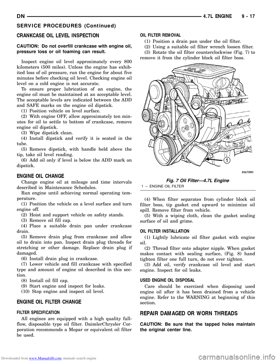
(3) Rotate the oil filter counterclockwise (Fig. 7) to
remove it from the cylinder block oil filter boss.
(4) When filter separates from cylinder block oil
filter boss, tip gasket end upward to minimize oil
spill. Remove filter from vehicle.
(5) With a wiping cloth, clean the gasket sealing
surface of oil and grime.
OIL FILTER INSTALLATION
(1) Lightly lubricate oil filter gasket with engine
oil.
(2) Thread filter onto adapter nipple. When gasket
makes contact with sealing surface, (Fig. 8) hand
tighten filter one full turn, do not over tighten.
(3) Add oil, verify crankcase oil level and start
engine. Inspect for oil leaks.
USED ENGINE OIL DISPOSAL
Care should be exercised when disposing used
engine oil after it has been drained from a vehicle
engine. Refer to the WARNING at beginning of this
section.REPAIR DAMAGED OR WORN THREADS
CAUTION: Be sure that the tapped holes maintain
the original center line.
Fig. 7 Oil FilterÐ4.7L Engine
1 ± ENGINE OIL FILTER
DN4.7L ENGINE 9 - 17
SERVICE PROCEDURES (Continued)
Page 19 of 193
Downloaded from www.Manualslib.com manuals search engine (6) Identify the fluid in the cylinders (i.e. coolant,
fuel, oil, etc.).
(7) Make sure all fluid has been removed from the
cylinders.
(8) Repair engine or components as necessary to
prevent this problem from occurring again.
(9) Squirt engine oil into the cylinders to lubricate
the walls. This will prevent damage on restart.
(10) Install new spark plugs.
(11) Drain engine oil. Remove and discard the oil
filter.
(12) Install the drain plug. Tighten the plug to 34
N´m (25 ft. lbs.) torque.
(13) Install a new oil filter.
(14) Fill engine crankcase with the specified
amount and grade of oil.
(15) Connect the negative cable to the battery.
(16) Start the engine and check for any leaks.
VALVE SERVICE
REFACING
NOTE: Valve seats that are worn or burned can be
reworked, provided that correct angle and seat
width are maintained. Otherwise the cylinder head
must be replaced.
NOTE: When refacing valves and valve seats, it is
important that the correct size valve guide pilot be
used for reseating stones. A true and complete sur-
face must be obtained.
(1) Using a suitable dial indicator measure the
center of the valve seat Total run out must not
exceed 0.051 mm (0.002 in).
(2) Apply a small amount of Prussian blue to the
valve seat, insert the valve into the cylinder head,
while applying light pressure on the valve rotate the
valve. Remove the valve and examine the valve face.
If the blue is transferred below the top edge of the
valve face, lower the valve seat using a 15 degree
stone. If the blue is transferred to the bottom edge of
the valve face, raise the valve seat using a 65 degree
stone.
(3) When the seat is properly positioned the width
of the intake seat must be 1.75 ± 2.36 mm (0.0689 ±
0.0928 in.) and the exhaust seat must be 1.71 ± 2.32
mm (0.0673 ± 0.0911 in.).
(4) Check the valve spring installed height after
refacing the valve and seat. The installed height for
both intake and exhaust valve springs must not
exceed 41.44 mm (1.6315 in.).
(5) The valve seat and valve face must maintain a
face angle of 44.5 ± 45 degrees angle.
ENGINE TIMINGÐVERIFICATION
CAUTION: The 4.7L is a non free-wheeling design
engine. Therefore, correct engine timing is critical.
NOTE: Components referred to as left hand or right
hand are as viewed from the drivers position inside
the vehicle.
NOTE: The blue link plates on the chains and the
dots on the camshaft drive sprockets may not line
up during the timing verification procedure. The
blue link plates are lined up with the sprocket dots
only when re-timing the complete timing drive.
Once the timing drive is rotated blue link-to-dot
alignment is no longer valid.
Engine base timing can be verified by the following
procedure:
(1) Remove the cylinder head covers. Refer to the
procedure in this section.
(2) Using a mirror, locate the TDC arrow on the
front cover (Fig. 11). Rotate the crankshaft until the
mark on the crankshaft damper is aligned with the
TDC arrow on the front cover. The engine is now at
TDC.
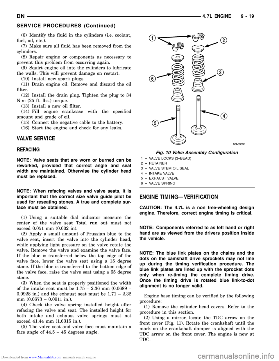
Fig. 10 Valve Assembly Configuration
1 ± VALVE LOCKS (3±BEAD)
2 ± RETAINER
3 ± VALVE STEM OIL SEAL
4 ± INTAKE VALVE
5 ± EXHAUST VALVE
6 ± VALVE SPRING
DN4.7L ENGINE 9 - 19
SERVICE PROCEDURES (Continued)
Page 41 of 193
Downloaded from www.Manualslib.com manuals search engine (4) For rocker arm installation on cylinders 1 and
7 Rotate the crankshaft until cylinder #2 is at TDC
compression stroke.
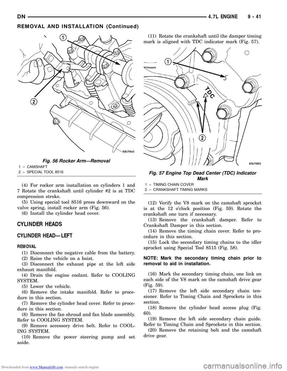
(5) Using special tool 8516 press downward on the
valve spring, install rocker arm (Fig. 56).
(6) Install the cylinder head cover.
CYLINDER HEADS
CYLINDER HEADÐLEFT
REMOVAL
(1) Disconnect the negative cable from the battery.
(2) Raise the vehicle on a hoist.
(3) Disconnect the exhaust pipe at the left side
exhaust manifold.
(4) Drain the engine coolant. Refer to COOLING
SYSTEM.
(5) Lower the vehicle.
(6) Remove the intake manifold. Refer to proce-
dure in this section.
(7) Remove the cylinder head cover. Refer to proce-
dure in this section.
(8) Remove the fan shroud and fan blade assembly.
Refer to COOLING SYSTEM.
(9) Remove accessory drive belt. Refer to COOL-
ING SYSTEM.
(10) Remove the power steering pump and set
aside.(11) Rotate the crankshaft until the damper timing
mark is aligned with TDC indicator mark (Fig. 57).
(12) Verify the V8 mark on the camshaft sprocket
is at the 12 o'clock position (Fig. 59). Rotate the
crankshaft one turn if necessary.
(13) Remove the crankshaft damper. Refer to
Crankshaft Damper in this section.
(14) Remove the timing chain cover. Refer to pro-
cedure in this section.
(15) Lock the secondary timing chains to the idler
sprocket using Special Tool 8515 (Fig. 58).
NOTE: Mark the secondary timing chain prior to
removal to aid in installation.
(16) Mark the secondary timing chain, one link on
each side of the V8 mark on the camshaft drive gear
(Fig. 59).
(17) Remove the left side secondary chain ten-
sioner. Refer to Timing Chain and Sprockets in this
section.
(18) Remove the cylinder head access plug (Fig.
60).
(19) Remove the left side secondary chain guide.
Refer to Timing Chain and Sprockets in this section.
(20) Remove the retaining bolt and the camshaft
drive gear.
Fig. 56 Rocker ArmÐRemoval
1 ± CAMSHAFT
2 ± SPECIAL TOOL 8516
Fig. 57 Engine Top Dead Center (TDC) Indicator
Mark
1 ± TIMING CHAIN COVER
2 ± CRANKSHAFT TIMING MARKS
DN4.7L ENGINE 9 - 41
REMOVAL AND INSTALLATION (Continued)
Page 44 of 193
Downloaded from www.Manualslib.com manuals search engine (14) Install the crankshaft damper. Tighten
damper bolt 175 N´m (130 Ft. Lbs.).
(15) Install the power steering pump.
(16) Install the fan blade assembly and fan
shroud.
(17) Install the cylinder head cover.
(18) Install the intake manifold.
(19) Refill the cooling system
(20) Raise the vehicle.
(21) Install the exhaust pipe onto the left exhaust
manifold.
(22) Lower the vehicle.
(23) Connect the negative cable to the battery.
(24) Start the engine and check for leaks.
CYLINDER HEADÐRIGHT
REMOVAL
(1) Disconnect battery negitive cable.
(2) Raise the vehicle on a hoist.
(3) Disconnect the exhaust pipe at the right side
exhaust manifold.
(4) Drain the engine coolant. Refer to COOLING
SYSTEM.
(5) Lower the vehicle.
(6) Remove the intake manifold. Refer to proce-
dure in this section.
(7) Remove the cylinder head cover. Refer to proce-
dure in this section.
(8) Remove the fan shroud. Refer to COOLING
SYSTEM.
(9) Remove oil fill housing from cylinder head.
(10) Remove accessory drive belt. Refer to COOL-
ING SYSTEM.
(11) Rotate the crankshaft until the damper timing
mark is aligned with TDC indicator mark (Fig. 57).
(12) Verify the V8 mark on the camshaft sprocket
is at the 12 o'clock position (Fig. 59). Rotate the
crankshaft one turn if necessary.
(13) Remove the crankshaft damper. Refer to
Crankshaft Damper in this section.(14) Remove the timing chain cover. Refer to Tim-
ing Chain Cover in this section.
(15) Lock the secondary timing chains to the idler
sprocket using Special Tool 8515 (Fig. 58).
NOTE: Mark the secondary timing chain prior to
removal to aid in installation.
(16) Mark the secondary timing chain, one link on
each side of the V8 mark on the camshaft drive gear
(Fig. 59).
(17) Remove the right side secondary chain ten-
sioner. Refer to Timing Chain and Sprockets in this
section.
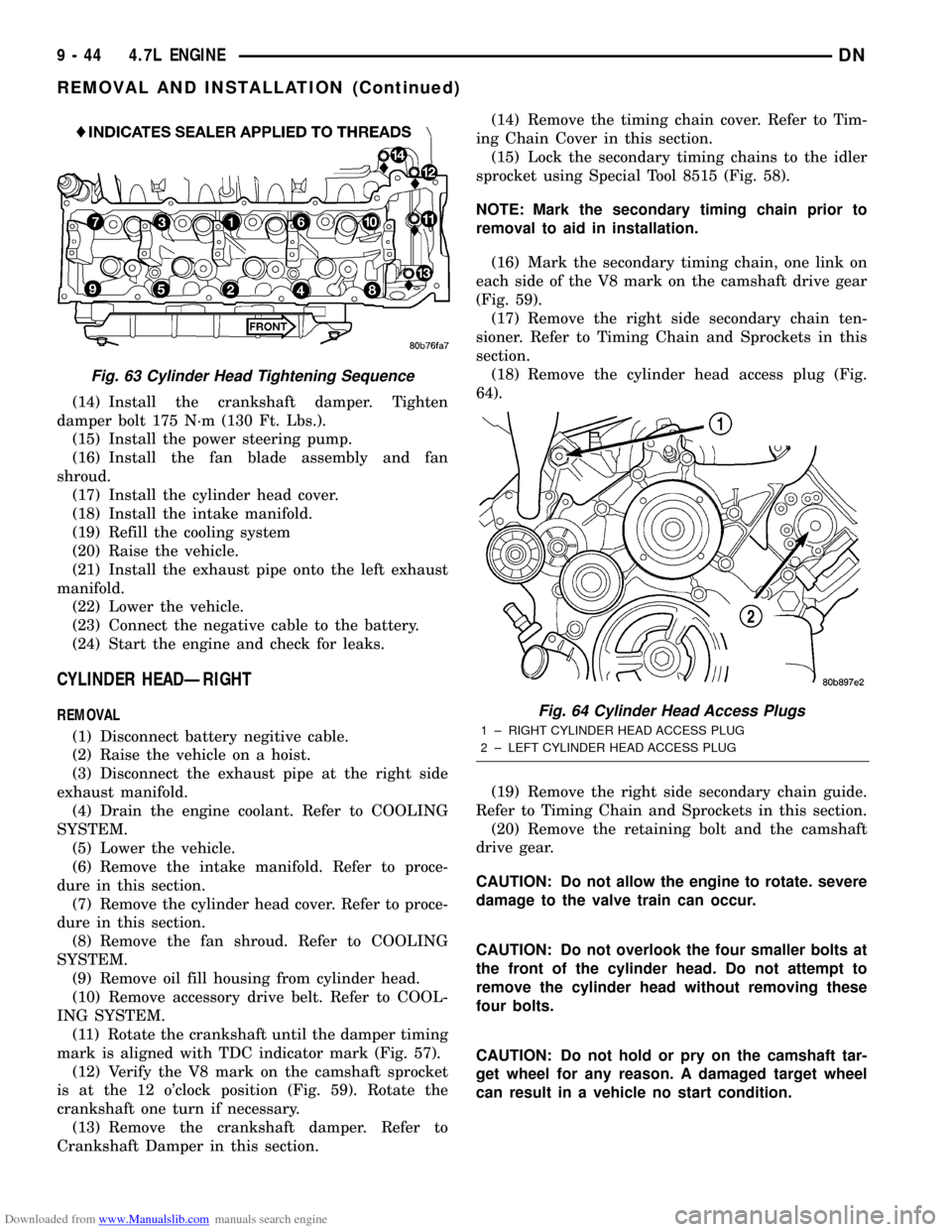
(18) Remove the cylinder head access plug (Fig.
64).
(19) Remove the right side secondary chain guide.
Refer to Timing Chain and Sprockets in this section.
(20) Remove the retaining bolt and the camshaft
drive gear.
CAUTION: Do not allow the engine to rotate. severe
damage to the valve train can occur.
CAUTION: Do not overlook the four smaller bolts at
the front of the cylinder head. Do not attempt to
remove the cylinder head without removing these
four bolts.
CAUTION: Do not hold or pry on the camshaft tar-
get wheel for any reason. A damaged target wheel
can result in a vehicle no start condition.
Fig. 63 Cylinder Head Tightening Sequence
Fig. 64 Cylinder Head Access Plugs
1 ± RIGHT CYLINDER HEAD ACCESS PLUG
2 ± LEFT CYLINDER HEAD ACCESS PLUG
9 - 44 4.7L ENGINEDN
REMOVAL AND INSTALLATION (Continued)
Page 49 of 193
Downloaded from www.Manualslib.com manuals search engine (3) Install the A/C compressor and generator.
(4) Install crankshaft damper. Refer to procedure
in this section.
(5) Install accessory drive belt tensioner assembly.
Tighten fastener to 54 N´m (40 ft. lbs.).
(6) Install lower radiator hose.
(7) Install both heater hoses.
(8) Install radiator shroud and viscous fan drive
assembly. Refer to Group 7, Cooling System for pro-
cedure.(9) Fill cooling system. Refer to Group 7, Cooling
System for procedures.
(10) Connect the battery negative cable.
TIMING CHAIN AND SPROCKETS
REMOVAL
(1) Disconnect negative cable from battery.
(2) Drain cooling system. Refer to Group 7, Cooling
System for procedures.
(3) Remove right and left cylinder head covers.
Refer to procedure in this section.
(4) Remove radiator fan shroud. Refer to Group 7,
Cooling System for procedure.
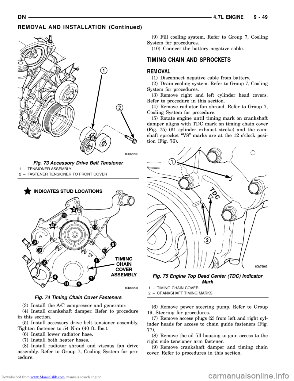
(5) Rotate engine until timing mark on crankshaft
damper aligns with TDC mark on timing chain cover
(Fig. 75) (#1 cylinder exhaust stroke) and the cam-
shaft sprocket ªV8º marks are at the 12 o'clock posi-
tion (Fig. 76).
(6) Remove power steering pump. Refer to Group
19, Steering for procedures.
(7) Remove access plugs (2) from left and right cyl-
inder heads for access to chain guide fasteners (Fig.
77).
(8) Remove the oil fill housing to gain access to the
right side tensioner arm fastener.
(9) Remove crankshaft damper and timing chain
cover. Refer to procedures in this section.
Fig. 73 Accessory Drive Belt Tensioner
1 ± TENSIONER ASSEMBLY
2 ± FASTENER TENSIONER TO FRONT COVER
Fig. 74 Timing Chain Cover Fasteners
Fig. 75 Engine Top Dead Center (TDC) Indicator
Mark
1 ± TIMING CHAIN COVER
2 ± CRANKSHAFT TIMING MARKS
DN4.7L ENGINE 9 - 49
REMOVAL AND INSTALLATION (Continued)
Page 74 of 193
Downloaded from www.Manualslib.com manuals search engine ENGINE CORE PLUGS
REMOVAL
(1) Drain the cooling system. Refer to Group 7,
Cooling System for procedure.
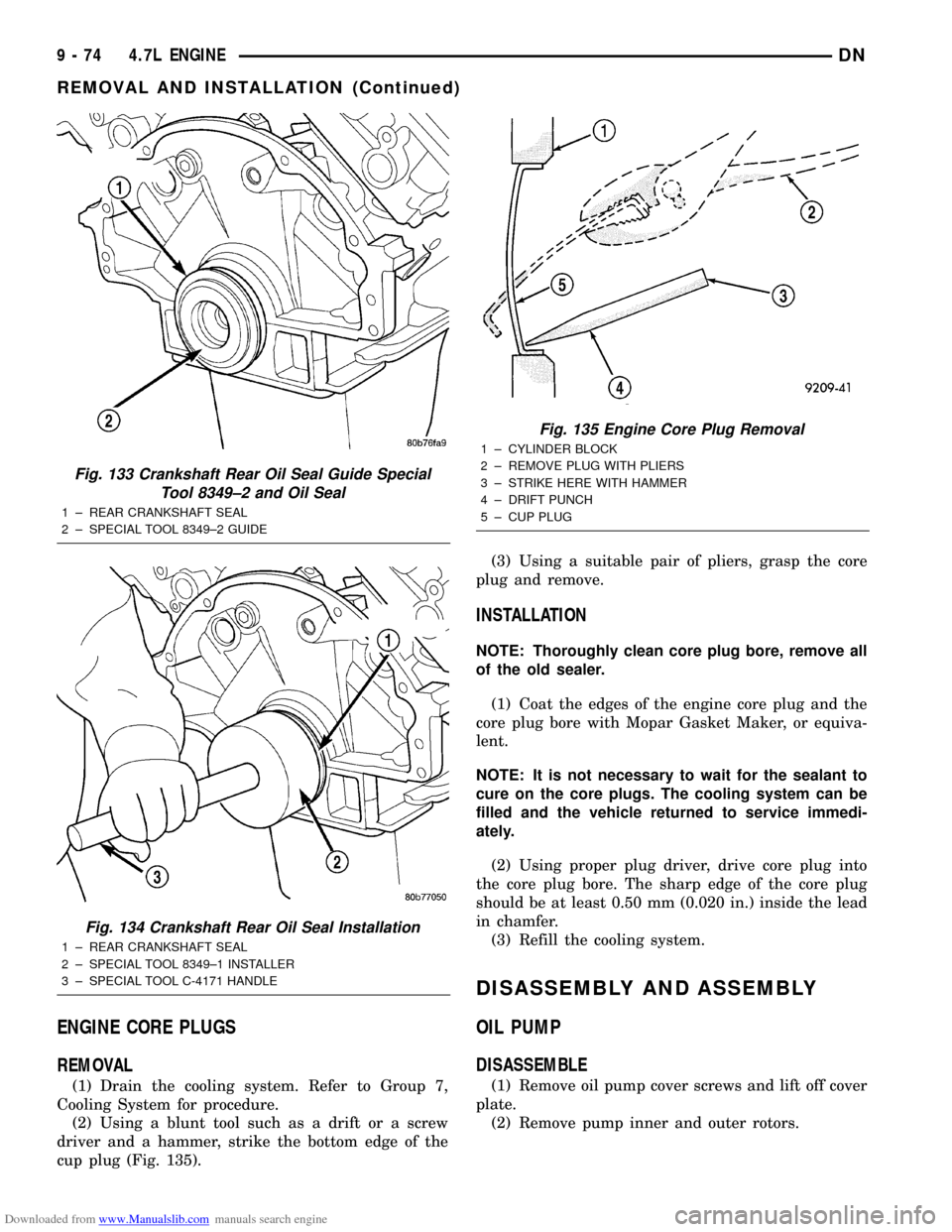
(2) Using a blunt tool such as a drift or a screw
driver and a hammer, strike the bottom edge of the
cup plug (Fig. 135).(3) Using a suitable pair of pliers, grasp the core
plug and remove.
INSTALLATION
NOTE: Thoroughly clean core plug bore, remove all
of the old sealer.
(1) Coat the edges of the engine core plug and the
core plug bore with Mopar Gasket Maker, or equiva-
lent.
NOTE: It is not necessary to wait for the sealant to
cure on the core plugs. The cooling system can be
filled and the vehicle returned to service immedi-
ately.
(2) Using proper plug driver, drive core plug into
the core plug bore. The sharp edge of the core plug
should be at least 0.50 mm (0.020 in.) inside the lead
in chamfer.
(3) Refill the cooling system.
DISASSEMBLY AND ASSEMBLY
OIL PUMP
DISASSEMBLE
(1) Remove oil pump cover screws and lift off cover
plate.
(2) Remove pump inner and outer rotors.
Fig. 133 Crankshaft Rear Oil Seal Guide Special
Tool 8349±2 and Oil Seal
1 ± REAR CRANKSHAFT SEAL
2 ± SPECIAL TOOL 8349±2 GUIDE
Fig. 134 Crankshaft Rear Oil Seal Installation
1 ± REAR CRANKSHAFT SEAL
2 ± SPECIAL TOOL 8349±1 INSTALLER
3 ± SPECIAL TOOL C-4171 HANDLE
Fig. 135 Engine Core Plug Removal
1 ± CYLINDER BLOCK
2 ± REMOVE PLUG WITH PLIERS
3 ± STRIKE HERE WITH HAMMER
4 ± DRIFT PUNCH
5 ± CUP PLUG
9 - 74 4.7L ENGINEDN
REMOVAL AND INSTALLATION (Continued)
Page 76 of 193
Downloaded from www.Manualslib.com manuals search engine PISTON AND CONNECTING ROD
CLEANING
CAUTION: DO NOT use a wire wheel or other abra-
sive cleaning devise to clean the pistons or con-
necting rods. The pistons have a Moly coating, this
coating must not be damaged.
(1) Using a suitable cleaning solvent clean the pis-
tons in warm water and towel dry.
(2) Use a wood or plastic scraper to clean the ring
land grooves.
CAUTION: DO NOT remove the piston pin from the
piston and connecting rod assembly.
INSPECTION
Check the crankshaft connecting rod journal for
excessive wear, taper and scoring.
Check the pistons for taper and elliptical shape
before they are fitted into the cylinder bore.
Replace any piston and connecting rod not meeting
the specifications.
OIL PAN
CLEANING
(1) Clean oil pan in solvent and wipe dry with a
clean cloth.
(2) Clean the oil pan gasket surface.DO NOTuse
a grinder wheel or other abrasive tool to clean seal-
ing surface.
(3) Clean oil screen and tube thoroughly in clean
solvent.
INSPECTION
(1) Inspect oil drain plug and plug hole for
stripped or damaged threads. Repair as necessary.
(2) Inspect the oil pan mounting flange for bends
or distortion. Straighten flange, if necessary.
OIL PUMP
CLEANING
(1) Wash all parts in a suitable solvent.
INSPECTION
CAUTION: Oil pump pressure relief valve and
spring should not be removed from the oil pump. If
the these components are disassembled andùr
removed from the pump the entire oil pump assem-
bly must be replaced.(1) Clean all parts thoroughly. Mating surface of
the oil pump housing should be smooth. If the pump
cover is scratched or grooved the oil pump assembly
should be replaced.
(2) Lay a straight edge across the pump cover sur-
face (Fig. 137). If a 0.025 mm (0.001 in.) feeler gauge
can be inserted between the cover and the straight
edge the oil pump assembly should be replaced.
(3) Measure the thickness of the outer rotor (Fig.
138). If the outer rotor thickness measures at 12.005
mm (0.400 in.) or less the oil pump assembly must be
replaced.
(4) Measure the diameter of the outer rotor. If the
outer rotor diameter measures at 85.925 mm (0.400
in.) or less the oil pump assembly must be replaced.
(5) Measure the thickness of the inner rotor (Fig.
139). If the inner rotor thickness measures at 12.005
mm (0.400 in.) or less then the oil pump assembly
must be replaced.
(6) Slide outer rotor into the body of the oil pump.
Press the outer rotor to one side of the oil pump body
and measure clearance between the outer rotor and
the body (Fig. 140). If the measurement is 0.47mm
(0.0186 in.) or more the oil pump assembly must be
replaced.
(7) Install the inner rotor in the into the oil pump
body. Measure the clearance between the inner and
outer rotors (Fig. 141). If the clearance between the
rotors is .150 mm (0.006 in.) or more the oil pump
assembly must be replaced.
(8) Place a straight edge across the body of the oil
pump (between the bolt holes), if a feeler gauge of
.095 mm (0.0038 in.) or greater can be inserted
between the straightedge and the rotors, the pump
must be replaced (Fig. 142).
NOTE: 4.7 Oil pump is released as an assembly.
There are no DaimlerChrysler part numbers for Sub-
Assembly components. In the event the oil pump is
not functioning or out of specification it must be
replaced as an assembly.
CYLINDER BLOCK
CLEANING
Thoroughly clean the oil pan and engine block gas-
ket surfaces.
Use compressed air to clean out:
²The galley at the oil filter adaptor hole.
²The front and rear oil galley holes.
²The feed holes for the crankshaft main bearings.
Once the block has been completely cleaned, apply
Loctite PST pipe sealant with Teflon 592 to the
threads of the front and rear oil galley plugs. Tighten
the plugs to 34 N´m (25 ft. lbs.) torque.
9 - 76 4.7L ENGINEDN
CLEANING AND INSPECTION (Continued)
Page 81 of 193
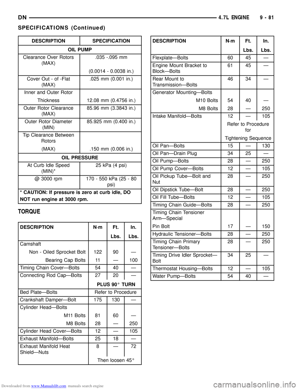
Downloaded from www.Manualslib.com manuals search engine DESCRIPTION SPECIFICATION
OIL PUMP
Clearance Over Rotors
(MAX).035 -.095 mm
(0.0014 - 0.0038 in.)
Cover Out - of -Flat
(MAX).025 mm (0.001 in.)
Inner and Outer Rotor
Thickness 12.08 mm (0.4756 in.)
Outer Rotor Clearance
(MAX)85.96 mm (3.3843 in.)
Outer Rotor Diameter
(MIN)85.925 mm (0.400 in.)
Tip Clearance Between
Rotors
(MAX) .150 mm (0.006 in.)
OIL PRESSURE
At Curb Idle Speed
(MIN)*25 kPa (4 psi)
@ 3000 rpm 170 - 550 kPa (25 - 80
psi)
* CAUTION: If pressure is zero at curb idle, DO
NOT run engine at 3000 rpm.
TORQUE
DESCRIPTION N´m Ft. In.
Lbs. Lbs.
Camshaft
Non - Oiled Sprocket Bolt 122 90 Ð
Bearing Cap Bolts 11 Ð 100
Timing Chain CoverÐBolts 54 40 Ð
Connecting Rod CapÐBolts 27 20 Ð
PLUS 90É TURN
Bed PlateÐBolts Refer to Procedure
Crankshaft DamperÐBolt 175 130 Ð
Cylinder HeadÐBolts
M11 Bolts 81 60 Ð
M8 Bolts 28 Ð 250
Cylinder Head CoverÐBolts 12 Ð 105
Exhaust ManifoldÐBolts 25 18 Ð
Exhaust Manifold Heat
ShieldÐNuts8Ð72
Then loosen 45É
DESCRIPTION N´m Ft. In.
Lbs. Lbs.
FlexplateÐBolts 60 45 Ð
Engine Mount Bracket to
BlockÐBolts61 45 Ð
Rear Mount to
TransmissionÐBolts46 34 Ð
Generator MountingÐBolts
M10 Bolts 54 40 Ð
M8 Bolts 28 Ð 250
Intake ManifoldÐBolts 12 Ð 105
Refer to Procedure
for
Tightening Sequence
Oil PanÐBolts 15 Ð 130
Oil PanÐDrain Plug 34 25 Ð
Oil PumpÐBolts 28 Ð 250
Oil Pump CoverÐBolts 12 Ð 105
Oil Pickup TubeÐBolt and
Nut28 Ð 250
Oil Dipstick TubeÐBolt 28 Ð 250
Oil Fill TubeÐBolts 12 Ð 105
Timing Chain GuideÐBolts 28 Ð 250
Timing Chain Tensioner
ArmÐSpecial
Pin Bolt 17 Ð 150
Hydraulic TensionerÐBolts 28 Ð 250
Timing Chain Primary
TensionerÐBolts28 Ð 250
Timing Drive Idler SprocketÐ
Bolt34 25 Ð
Thermostat HousingÐBolts 12 Ð 105
Water PumpÐBolts 54 40 Ð
DN4.7L ENGINE 9 - 81
SPECIFICATIONS (Continued)
Page 90 of 193
Downloaded from www.Manualslib.com manuals search engine CYLINDER HEAD COVER GASKET
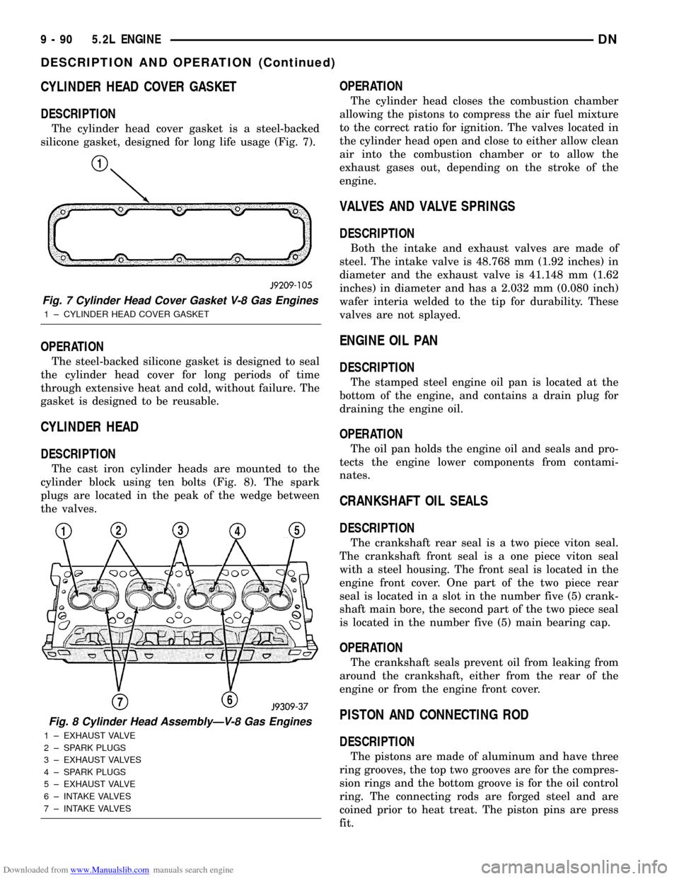
DESCRIPTION
The cylinder head cover gasket is a steel-backed
silicone gasket, designed for long life usage (Fig. 7).
OPERATION
The steel-backed silicone gasket is designed to seal
the cylinder head cover for long periods of time
through extensive heat and cold, without failure. The
gasket is designed to be reusable.
CYLINDER HEAD
DESCRIPTION
The cast iron cylinder heads are mounted to the
cylinder block using ten bolts (Fig. 8). The spark
plugs are located in the peak of the wedge between
the valves.
OPERATION
The cylinder head closes the combustion chamber
allowing the pistons to compress the air fuel mixture
to the correct ratio for ignition. The valves located in
the cylinder head open and close to either allow clean
air into the combustion chamber or to allow the
exhaust gases out, depending on the stroke of the
engine.
VALVES AND VALVE SPRINGS
DESCRIPTION
Both the intake and exhaust valves are made of
steel. The intake valve is 48.768 mm (1.92 inches) in
diameter and the exhaust valve is 41.148 mm (1.62
inches) in diameter and has a 2.032 mm (0.080 inch)
wafer interia welded to the tip for durability. These
valves are not splayed.
ENGINE OIL PAN
DESCRIPTION
The stamped steel engine oil pan is located at the
bottom of the engine, and contains a drain plug for
draining the engine oil.
OPERATION
The oil pan holds the engine oil and seals and pro-
tects the engine lower components from contami-
nates.
CRANKSHAFT OIL SEALS
DESCRIPTION
The crankshaft rear seal is a two piece viton seal.
The crankshaft front seal is a one piece viton seal
with a steel housing. The front seal is located in the
engine front cover. One part of the two piece rear
seal is located in a slot in the number five (5) crank-
shaft main bore, the second part of the two piece seal
is located in the number five (5) main bearing cap.
OPERATION
The crankshaft seals prevent oil from leaking from
around the crankshaft, either from the rear of the
engine or from the engine front cover.
PISTON AND CONNECTING ROD
DESCRIPTION
The pistons are made of aluminum and have three
ring grooves, the top two grooves are for the compres-
sion rings and the bottom groove is for the oil control
ring. The connecting rods are forged steel and are
coined prior to heat treat. The piston pins are press
fit.
Fig. 7 Cylinder Head Cover Gasket V-8 Gas Engines
1 ± CYLINDER HEAD COVER GASKET
Fig. 8 Cylinder Head AssemblyÐV-8 Gas Engines
1 ± EXHAUST VALVE
2 ± SPARK PLUGS
3 ± EXHAUST VALVES
4 ± SPARK PLUGS
5 ± EXHAUST VALVE
6 ± INTAKE VALVES
7 ± INTAKE VALVES
9 - 90 5.2L ENGINEDN
DESCRIPTION AND OPERATION (Continued)
Page 93 of 193
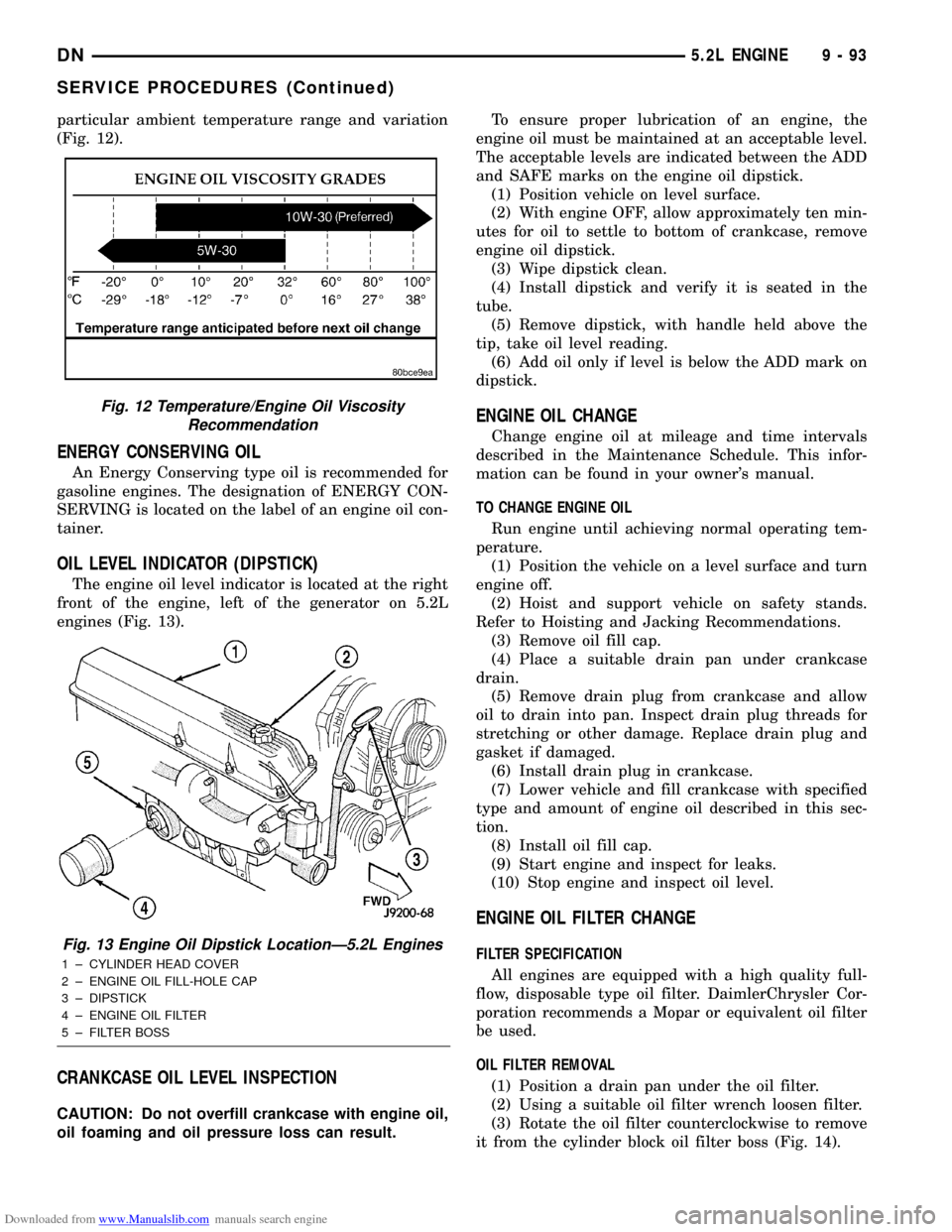
Downloaded from www.Manualslib.com manuals search engine particular ambient temperature range and variation
(Fig. 12).
ENERGY CONSERVING OIL
An Energy Conserving type oil is recommended for
gasoline engines. The designation of ENERGY CON-
SERVING is located on the label of an engine oil con-
tainer.
OIL LEVEL INDICATOR (DIPSTICK)
The engine oil level indicator is located at the right
front of the engine, left of the generator on 5.2L
engines (Fig. 13).
CRANKCASE OIL LEVEL INSPECTION
CAUTION: Do not overfill crankcase with engine oil,
oil foaming and oil pressure loss can result.To ensure proper lubrication of an engine, the
engine oil must be maintained at an acceptable level.
The acceptable levels are indicated between the ADD
and SAFE marks on the engine oil dipstick.
(1) Position vehicle on level surface.
(2) With engine OFF, allow approximately ten min-
utes for oil to settle to bottom of crankcase, remove
engine oil dipstick.
(3) Wipe dipstick clean.
(4) Install dipstick and verify it is seated in the
tube.
(5) Remove dipstick, with handle held above the
tip, take oil level reading.
(6) Add oil only if level is below the ADD mark on
dipstick.
ENGINE OIL CHANGE
Change engine oil at mileage and time intervals
described in the Maintenance Schedule. This infor-
mation can be found in your owner's manual.
TO CHANGE ENGINE OIL
Run engine until achieving normal operating tem-
perature.
(1) Position the vehicle on a level surface and turn
engine off.
(2) Hoist and support vehicle on safety stands.
Refer to Hoisting and Jacking Recommendations.
(3) Remove oil fill cap.
(4) Place a suitable drain pan under crankcase
drain.
(5) Remove drain plug from crankcase and allow
oil to drain into pan. Inspect drain plug threads for
stretching or other damage. Replace drain plug and
gasket if damaged.
(6) Install drain plug in crankcase.
(7) Lower vehicle and fill crankcase with specified
type and amount of engine oil described in this sec-
tion.
(8) Install oil fill cap.
(9) Start engine and inspect for leaks.
(10) Stop engine and inspect oil level.
ENGINE OIL FILTER CHANGE
FILTER SPECIFICATION
All engines are equipped with a high quality full-
flow, disposable type oil filter. DaimlerChrysler Cor-
poration recommends a Mopar or equivalent oil filter
be used.
OIL FILTER REMOVAL
(1) Position a drain pan under the oil filter.
(2) Using a suitable oil filter wrench loosen filter.
(3) Rotate the oil filter counterclockwise to remove
it from the cylinder block oil filter boss (Fig. 14).
Fig. 12 Temperature/Engine Oil Viscosity
Recommendation
Fig. 13 Engine Oil Dipstick LocationÐ5.2L Engines
1 ± CYLINDER HEAD COVER
2 ± ENGINE OIL FILL-HOLE CAP
3 ± DIPSTICK
4 ± ENGINE OIL FILTER
5 ± FILTER BOSS
DN5.2L ENGINE 9 - 93
SERVICE PROCEDURES (Continued)