Jack DODGE DURANGO 1999 1.G Workshop Manual
[x] Cancel search | Manufacturer: DODGE, Model Year: 1999, Model line: DURANGO, Model: DODGE DURANGO 1999 1.GPages: 193, PDF Size: 5.65 MB
Page 12 of 193
Downloaded from www.Manualslib.com manuals search engine Otherwise the indicated compression pressures may
not be valid for diagnosis purposes.
(1) Clean the spark plug recesses with compressed
air.
(2) Remove the spark plugs.
(3) Secure the throttle in the wide-open position.
(4) Disable the fuel system. (Refer to Group 14,
Fuel System for the correct procedure)
(5) Disconnect the ignition coil.
(6) Insert a compression pressure gauge and rotate
the engine with the engine starter motor for three
revolutions.
(7) Record the compression pressure on the 3rd
revolution. Continue the test for the remaining cylin-
ders.
Refer to Engine Specifications for the correct
engine compression pressures.
CYLINDER HEAD GASKET FAILURE DIAGNOSIS
A cylinder head gasket leak can be located between
adjacent cylinders or between a cylinder and the
adjacent water jacket.
²Possible indications of the cylinder head gasket
leaking between adjacent cylinders are:
²Loss of engine power
²Engine misfiring
²Poor fuel economy
²Possible indications of the cylinder head gasket
leaking between a cylinder and an adjacent water
jacket are:
²Engine overheating
²Loss of coolant
²Excessive steam (white smoke) emitting from
exhaust
²Coolant foaming
CYLINDER-TO-CYLINDER LEAKAGE TEST
To determine if an engine cylinder head gasket is
leaking between adjacent cylinders, follow the proce-
dures in Cylinder Compression Pressure Test in this
section. An engine cylinder head gasket leaking
between adjacent cylinders will result in approxi-
mately a 50±70% reduction in compression pressure.
CYLINDER-TO-WATER JACKET LEAKAGE TEST
WARNING: USE EXTREME CAUTION WHEN THE
ENGINE IS OPERATING WITH COOLANT PRES-
SURE CAP REMOVED.
VISUAL TEST METHOD
With the engine cool, remove the coolant pressure
cap. Start the engine and allow it to warm up until
thermostat opens.
If a large combustion/compression pressure leak
exists, bubbles will be visible in the coolant.COOLING SYSTEM TESTER METHOD
WARNING: WITH COOLING SYSTEM TESTER IN
PLACE, PRESSURE WILL BUILD UP FAST. EXCES-
SIVE PRESSURE BUILT UP, BY CONTINUOUS
ENGINE OPERATION, MUST BE RELEASED TO A
SAFE PRESSURE POINT. NEVER PERMIT PRES-
SURE TO EXCEED 138 kPa (20 psi).
Install Cooling System Tester 7700 or equivalent to
pressure cap neck. Start the engine and observe the
tester's pressure gauge. If gauge pulsates with every
power stroke of a cylinder a combustion pressure
leak is evident.
CHEMICAL TEST METHOD
Combustion leaks into the cooling system can also
be checked by using Bloc-Chek Kit C-3685-A or
equivalent. Perform test following the procedures
supplied with the tool kit.
CYLINDER COMBUSTION PRESSURE LEAKAGE
TEST
The combustion pressure leakage test provides an
accurate means for determining engine condition.
Combustion pressure leakage testing will detect:
²Exhaust and intake valve leaks (improper seat-
ing).
²Leaks between adjacent cylinders or into water
jacket.
²Any causes for combustion/compression pressure
loss.
(1) Check the coolant level and fill as required. DO
NOT install the radiator cap.
(2) Start and operate the engine until it attains
normal operating temperature, then turn the engine
OFF.
(3) Remove the spark plugs.
(4) Remove the oil filler cap.
(5) Remove the air cleaner.
(6)
Calibrate the tester according to the manufacturer's
instructions. The shop air source for testing should main-
tain 483 kPa (70 psi) minimum, 1,379 kPa (200 psi) maxi-
mum and 552 kPa (80 psi) recommended.
(7) Perform the test procedures on each cylinder
according to the tester manufacturer's instructions.
While testing, listen for pressurized air escaping
through the throttle body, tailpipe and oil filler cap
opening. Check for bubbles in the radiator coolant.
All gauge pressure indications should be equal,
with no more than 25% leakage.
FOR EXAMPLE:At 552 kPa (80 psi) input pres-
sure, a minimum of 414 kPa (60 psi) should be main-
tained in the cylinder.
Refer to the Cylinder Combustion Pressure Leak-
age Test Diagnosis chart.
9 - 12 4.7L ENGINEDN
DIAGNOSIS AND TESTING (Continued)
Page 28 of 193
Downloaded from www.Manualslib.com manuals search engine nal diameter specification (Main Bearing Fitting
Chart). Select inserts required to obtain the specified
bearing-to-journal clearance.
Install the crankshaft into the cylinder block. Refer
to Crankshaft in this section for procedure.
CRANKSHAFT MAIN BEARING SELECTION
(1) Service main bearings are available in three
grades. The chart below identifies the three service
grades available.
REMOVAL AND INSTALLATION
ENGINE MOUNTSÐLEFT AND RIGHT
REMOVAL
(1) Disconnect the negative cable from the battery.
CAUTION: Remove the fan blade, fan clutch and
fan shroud before raising engine. Failure to do so
may cause damage to the fan blade, fan clutch and
fan shroud.
(2) Remove the fan blade, fan clutch and fan
shroud. Refer to Group 7. for procedure.
(3) Remove the engine oil filter.
(4) Support the engine with a suitable jack and a
block of wood across the full width of the engine oil
pan.
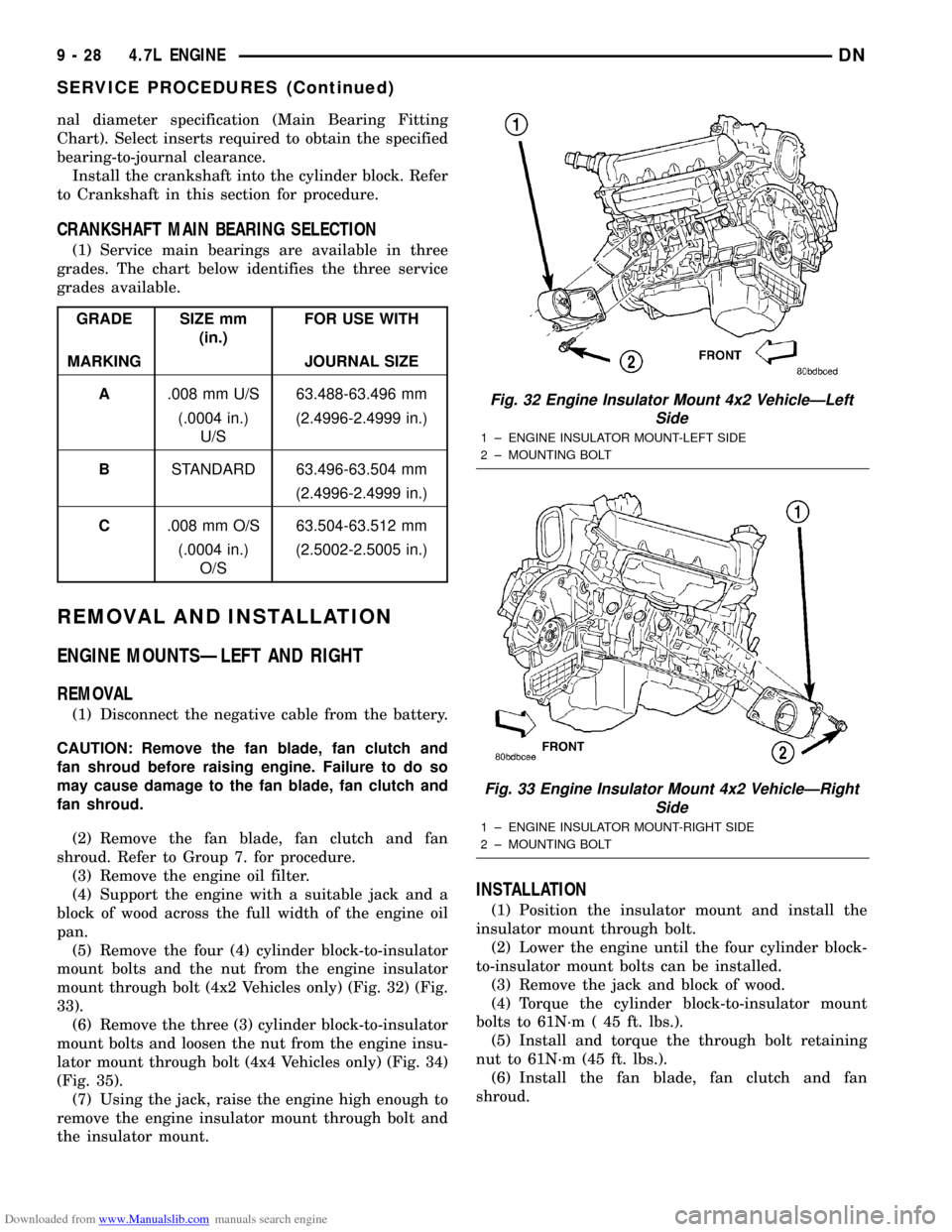
(5) Remove the four (4) cylinder block-to-insulator
mount bolts and the nut from the engine insulator
mount through bolt (4x2 Vehicles only) (Fig. 32) (Fig.
33).
(6) Remove the three (3) cylinder block-to-insulator
mount bolts and loosen the nut from the engine insu-
lator mount through bolt (4x4 Vehicles only) (Fig. 34)
(Fig. 35).
(7) Using the jack, raise the engine high enough to
remove the engine insulator mount through bolt and
the insulator mount.
INSTALLATION
(1) Position the insulator mount and install the
insulator mount through bolt.
(2) Lower the engine until the four cylinder block-
to-insulator mount bolts can be installed.
(3) Remove the jack and block of wood.
(4) Torque the cylinder block-to-insulator mount
bolts to 61N´m ( 45 ft. lbs.).
(5) Install and torque the through bolt retaining
nut to 61N´m (45 ft. lbs.).
(6) Install the fan blade, fan clutch and fan
shroud.
GRADE SIZE mm
(in.)FOR USE WITH
MARKING JOURNAL SIZE
A.008 mm U/S 63.488-63.496 mm
(.0004 in.)
U/S(2.4996-2.4999 in.)
BSTANDARD 63.496-63.504 mm
(2.4996-2.4999 in.)
C.008 mm O/S 63.504-63.512 mm
(.0004 in.)
O/S(2.5002-2.5005 in.)
Fig. 32 Engine Insulator Mount 4x2 VehicleÐLeft
Side
1 ± ENGINE INSULATOR MOUNT-LEFT SIDE
2 ± MOUNTING BOLT
Fig. 33 Engine Insulator Mount 4x2 VehicleÐRight
Side
1 ± ENGINE INSULATOR MOUNT-RIGHT SIDE
2 ± MOUNTING BOLT
9 - 28 4.7L ENGINEDN
SERVICE PROCEDURES (Continued)
Page 29 of 193
Downloaded from www.Manualslib.com manuals search engine ENGINE MOUNTÐREAR
REMOVAL
(1) Raise vehicle on hoist.
(2) Using a suitable jack, support transmission.
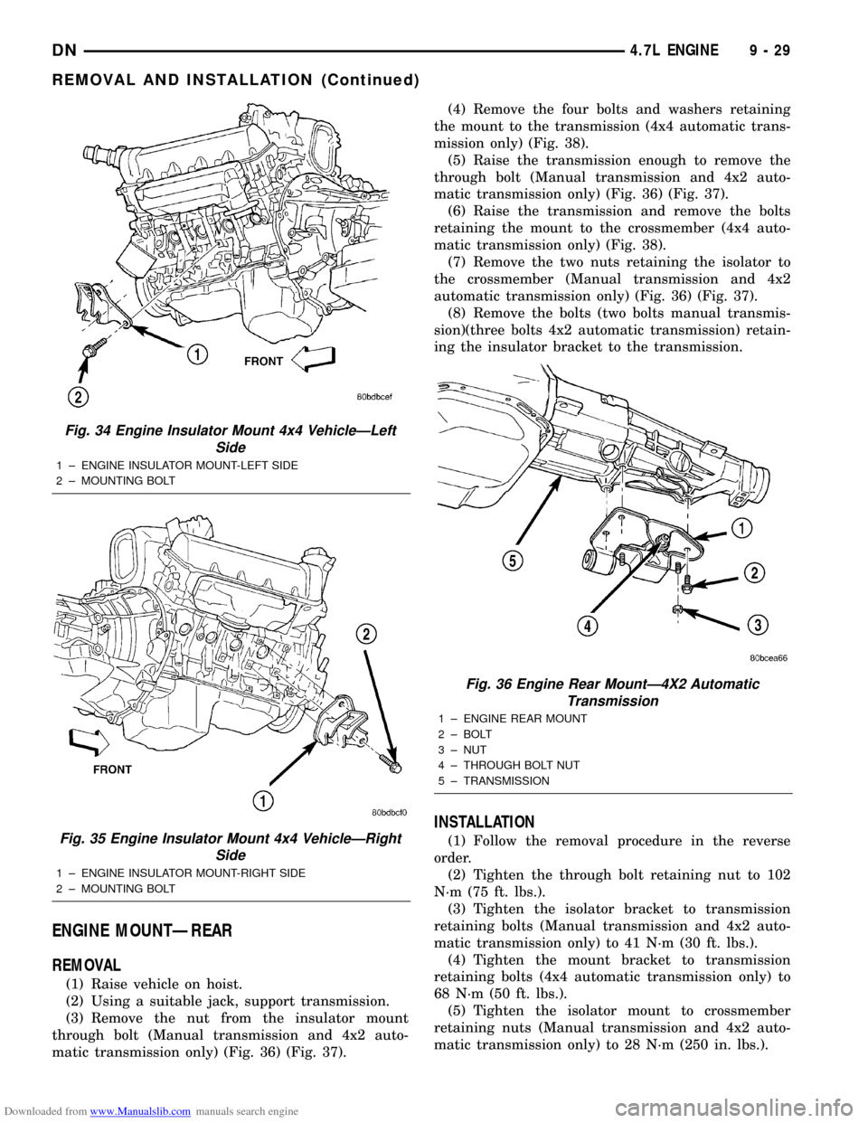
(3) Remove the nut from the insulator mount
through bolt (Manual transmission and 4x2 auto-
matic transmission only) (Fig. 36) (Fig. 37).(4) Remove the four bolts and washers retaining
the mount to the transmission (4x4 automatic trans-
mission only) (Fig. 38).
(5) Raise the transmission enough to remove the
through bolt (Manual transmission and 4x2 auto-
matic transmission only) (Fig. 36) (Fig. 37).
(6) Raise the transmission and remove the bolts
retaining the mount to the crossmember (4x4 auto-
matic transmission only) (Fig. 38).
(7) Remove the two nuts retaining the isolator to
the crossmember (Manual transmission and 4x2
automatic transmission only) (Fig. 36) (Fig. 37).
(8) Remove the bolts (two bolts manual transmis-
sion)(three bolts 4x2 automatic transmission) retain-
ing the insulator bracket to the transmission.
INSTALLATION
(1) Follow the removal procedure in the reverse
order.
(2) Tighten the through bolt retaining nut to 102
N´m (75 ft. lbs.).
(3) Tighten the isolator bracket to transmission
retaining bolts (Manual transmission and 4x2 auto-
matic transmission only) to 41 N´m (30 ft. lbs.).
(4) Tighten the mount bracket to transmission
retaining bolts (4x4 automatic transmission only) to
68 N´m (50 ft. lbs.).
(5) Tighten the isolator mount to crossmember
retaining nuts (Manual transmission and 4x2 auto-
matic transmission only) to 28 N´m (250 in. lbs.).
Fig. 34 Engine Insulator Mount 4x4 VehicleÐLeft
Side
1 ± ENGINE INSULATOR MOUNT-LEFT SIDE
2 ± MOUNTING BOLT
Fig. 35 Engine Insulator Mount 4x4 VehicleÐRight
Side
1 ± ENGINE INSULATOR MOUNT-RIGHT SIDE
2 ± MOUNTING BOLT
Fig. 36 Engine Rear MountÐ4X2 Automatic
Transmission
1 ± ENGINE REAR MOUNT
2 ± BOLT
3 ± NUT
4 ± THROUGH BOLT NUT
5 ± TRANSMISSION
DN4.7L ENGINE 9 - 29
REMOVAL AND INSTALLATION (Continued)
Page 32 of 193
Downloaded from www.Manualslib.com manuals search engine ²Throttle Position (TPS) Switch
²Idle Air Control (IAC) Motor
²Engine Oil Pressure Switch
²Engine Coolant Temperature (ECT) Sensor
²Manifold absolute pressure (MAP) Sensor
²Camshaft Position (CMP) Sensor
²Coil Over Plugs
(31) Disconnect the vacuum lines at the throttle
body and intake manifold.
(32) Release fuel rail pressure then disconnect the
fuel supply quick connect fitting at the fuel rail.
Refer toFUEL SYSTEM for procedure.
(33) Remove power steering pump and position out
of the way.
(34) Install Special Tools 8400 Lifting Studs, into
the cylinder heads.
(35) Install Engine Lifting Fixture Special Tool
8347 (Fig. 47) following these steps.
²Holding the lifting fixture at a slight angle, slide
the large bore in the front plate over the hex portion
of the lifting stud.
²Position the two remaining fixture arms onto
the two Special Tools 8400 Lifting Studs, in the cyl-
inder heads.
²Pull foward and upward on the lifting fixture so
that the lifting stud rest in the slotted area below the
large bore.²Secure the lifting fixture to the three studs
using three 7/16 ± 14 N/C locknuts.
²Make sure the lifting loop in the lifting fixture is
in the last hole (closest to the throttle body) to min-
imize the angle of engine during removal.
(36) Disconnect body ground strap at the right side
cowl (Fig. 48).
(37) Disconnect body ground strap at the left side
cowl (Fig. 49).
NOTE: It will be necessary to support the transmis-
sion in order to remove the engine.
(38) Position a suitable jack under the transmis-
sion.
(39) Remove engine from the vehicle.
INSTALLATION
(1) Position engine in the vehicle.
Position both the left and right side engine mount
brackets and install the through bolts and nuts.
Tighten nuts to4X2 vehicles95 N´m (70 ft. lbs.).
4X4 vehicles102 N´m (75 ft. lbs.).
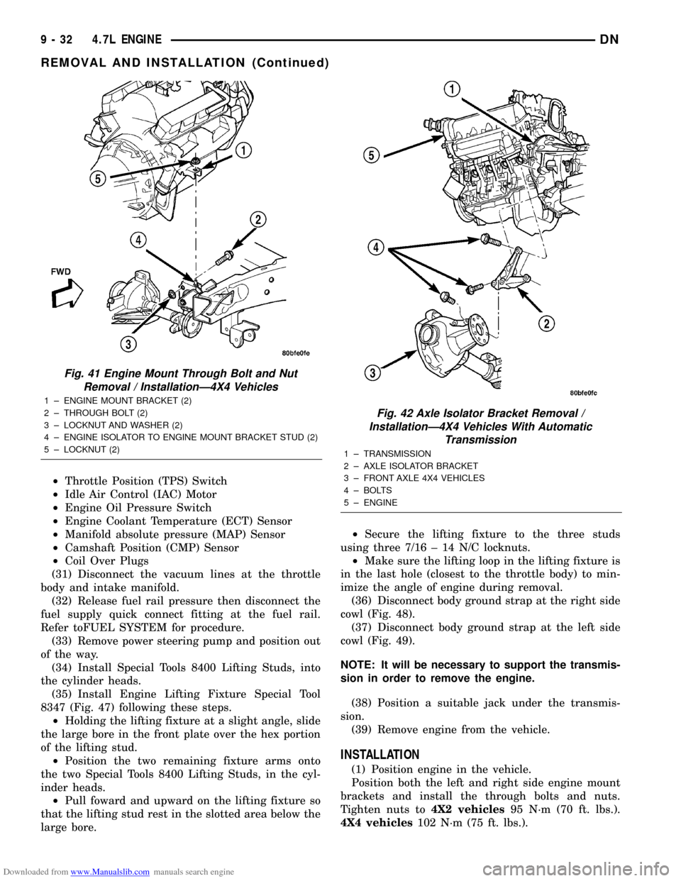
Fig. 41 Engine Mount Through Bolt and Nut
Removal / InstallationÐ4X4 Vehicles
1 ± ENGINE MOUNT BRACKET (2)
2 ± THROUGH BOLT (2)
3 ± LOCKNUT AND WASHER (2)
4 ± ENGINE ISOLATOR TO ENGINE MOUNT BRACKET STUD (2)
5 ± LOCKNUT (2)
Fig. 42 Axle Isolator Bracket Removal /
InstallationÐ4X4 Vehicles With Automatic
Transmission
1 ± TRANSMISSION
2 ± AXLE ISOLATOR BRACKET
3 ± FRONT AXLE 4X4 VEHICLES
4 ± BOLTS
5 ± ENGINE
9 - 32 4.7L ENGINEDN
REMOVAL AND INSTALLATION (Continued)
Page 33 of 193
Downloaded from www.Manualslib.com manuals search engine (2)4X4 vehiclesInstall locknuts onto the engine
mount brackets. Tighten locknuts to 41 N´m (30 ft.
lbs.).
(3) Remove jack from under the transmission.
(4) Remove Engine Lifting Fixture Special Tool
8347 (Fig. 47).
(5) Remove Special Tools 8400 Lifting Studs.
(6) Position generator wiring behind the oil dip-
stick tube, then install the oil dipstick tube upper
mounting bolt.
(7) Connect both left and right side body ground
straps.(8) Install power steering pump.
(9) Connect fuel supply line quick connect fitting.
(10) Connect the vacuum lines at the throttle body
and intake manifold.
(11) Connect engine harness at the following
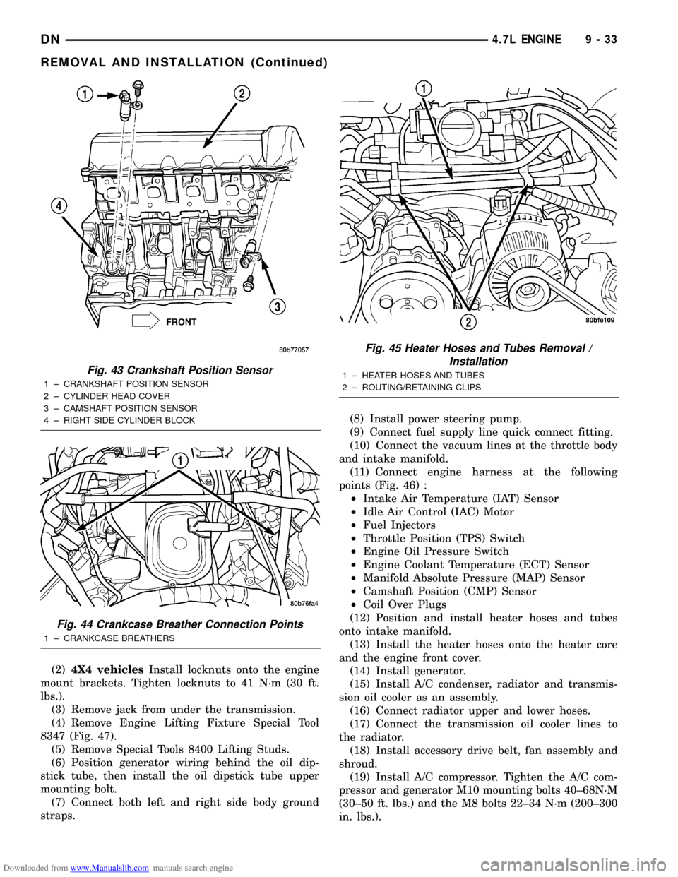
points (Fig. 46) :
²Intake Air Temperature (IAT) Sensor
²Idle Air Control (IAC) Motor
²Fuel Injectors
²Throttle Position (TPS) Switch
²Engine Oil Pressure Switch
²Engine Coolant Temperature (ECT) Sensor
²Manifold Absolute Pressure (MAP) Sensor
²Camshaft Position (CMP) Sensor
²Coil Over Plugs
(12) Position and install heater hoses and tubes
onto intake manifold.
(13) Install the heater hoses onto the heater core
and the engine front cover.
(14) Install generator.
(15) Install A/C condenser, radiator and transmis-
sion oil cooler as an assembly.
(16) Connect radiator upper and lower hoses.
(17) Connect the transmission oil cooler lines to
the radiator.
(18) Install accessory drive belt, fan assembly and
shroud.
(19) Install A/C compressor. Tighten the A/C com-
pressor and generator M10 mounting bolts 40±68N´M
(30±50 ft. lbs.) and the M8 bolts 22±34 N´m (200±300
in. lbs.).
Fig. 43 Crankshaft Position Sensor
1 ± CRANKSHAFT POSITION SENSOR
2 ± CYLINDER HEAD COVER
3 ± CAMSHAFT POSITION SENSOR
4 ± RIGHT SIDE CYLINDER BLOCK
Fig. 44 Crankcase Breather Connection Points
1 ± CRANKCASE BREATHERS
Fig. 45 Heater Hoses and Tubes Removal /
Installation
1 ± HEATER HOSES AND TUBES
2 ± ROUTING/RETAINING CLIPS
DN4.7L ENGINE 9 - 33
REMOVAL AND INSTALLATION (Continued)
Page 61 of 193
Downloaded from www.Manualslib.com manuals search engine INSTALLATION
(1) Lubricate camshaft journals with clean engine
oil.
NOTE: Position the right side camshaft so that the
camshaft sprocket dowel is near the 10 o'clock
position, This will place the camshaft at the neutral
position easing the installation of the camshaft
bearing caps.
(2) Position the camshaft into the cylinder head.
(3) Install the camshaft bearing caps, hand tighten
the retaining bolts.
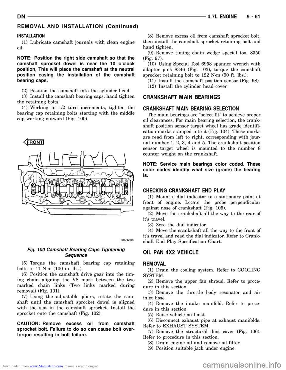
(4) Working in 1/2 turn increments, tighten the
bearing cap retaining bolts starting with the middle
cap working outward (Fig. 100).
(5) Torque the camshaft bearing cap retaining
bolts to 11 N´m (100 in. lbs.).
(6) Position the camshaft drive gear into the tim-
ing chain aligning the V8 mark between the two
marked chain links (Two links marked during
removal) (Fig. 101).
(7) Using the adjustable pliers, rotate the cam-
shaft until the camshaft sprocket dowel is aligned
with the slot in the camshaft sprocket. Install the
sprocket onto the camshaft (Fig. 102).
CAUTION: Remove excess oil from camshaft
sprocket bolt. Failure to do so can cause bolt over-
torque resulting in bolt failure.(8) Remove excess oil from camshaft sprocket bolt,
then install the camshaft sprocket retaining bolt and
hand tighten.
(9) Remove timing chain wedge special tool 8350
(Fig. 97).
(10) Using Special Tool 6958 spanner wrench with
adapter pins 8346 (Fig. 103), torque the camshaft
sprocket retaining bolt to 122 N´m (90 ft. lbs.).
(11) Install the camshaft position sensor (Fig. 98).
(12) Install the cylinder head cover.
CRANKSHAFT MAIN BEARINGS
CRANKSHAFT MAIN BEARING SELECTION
The main bearings are ªselect fitº to achieve proper
oil clearances. For main bearing selection, the crank-
shaft position sensor target wheel has grade identifi-
cation marks stamped into it (Fig. 104). These marks
are read from left to right, corresponding with jour-
nal number 1, 2, 3, 4 and 5. The crankshaft position
sensor target wheel is mounted to the number 8
counter weight on the crankshaft.
NOTE: Service main bearings color coded. These
color codes identify what size (grade) the bearing
is.
CHECKING CRANKSHAFT END PLAY
(1) Mount a dial indicator to a stationary point at
front of engine. Locate the probe perpendicular
against nose of crankshaft (Fig. 105).
(2) Move the crankshaft all the way to the rear of
it's travel.
(3) Zero the dial indicator.
(4) Move the crankshaft all the way to the front of
it's travel and read the dial indicator. Refer to Crank-
shaft End Play Specification Chart.
OIL PAN 4X2 VEHICLE
REMOVAL
(1) Drain the cooling system. Refer to COOLING
SYSTEM.
(2) Remove the upper fan shroud. Refer to proce-
dure in this section.
(3) Remove the throttle body resonator and air
inlet hose.
(4) Remove the intake manifold. Refer to proce-
dure in this section.
(5) Raise vehicle on hoist.
(6) Disconnect exhaust pipe at exhaust manifolds.
Refer to EXHAUST SYSTEM.
(7) Remove the structural dust cover (Fig. 106).
Refer to procedure in this section.
(8) Drain engine oil and remove oil filter.
(9) Position suitable jack under engine.
Fig. 100 Camshaft Bearing Caps Tightening
Sequence
DN4.7L ENGINE 9 - 61
REMOVAL AND INSTALLATION (Continued)
Page 64 of 193
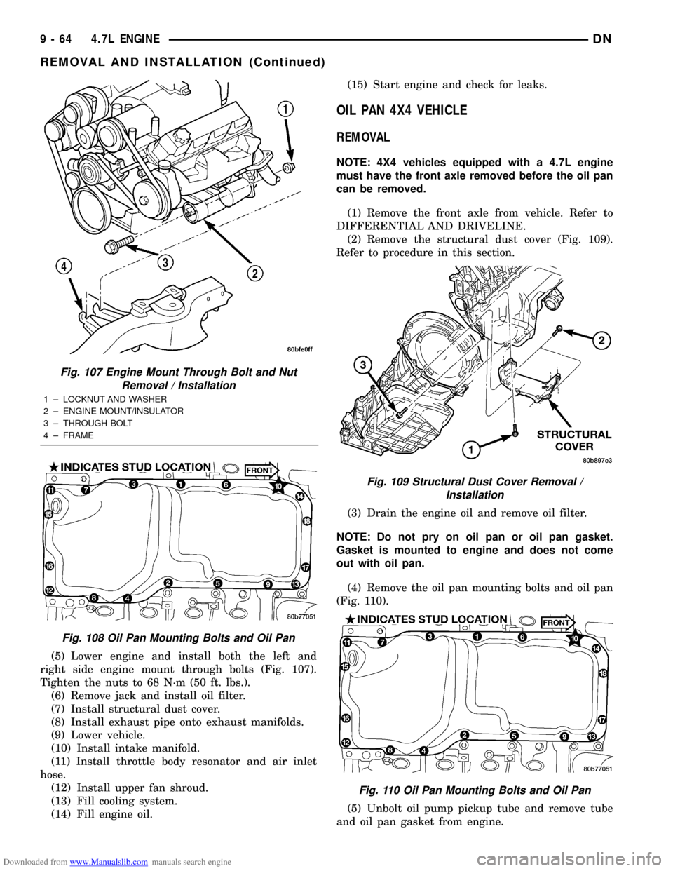
Downloaded from www.Manualslib.com manuals search engine (5) Lower engine and install both the left and
right side engine mount through bolts (Fig. 107).
Tighten the nuts to 68 N´m (50 ft. lbs.).
(6) Remove jack and install oil filter.
(7) Install structural dust cover.
(8) Install exhaust pipe onto exhaust manifolds.
(9) Lower vehicle.
(10) Install intake manifold.
(11) Install throttle body resonator and air inlet
hose.
(12) Install upper fan shroud.
(13) Fill cooling system.
(14) Fill engine oil.(15) Start engine and check for leaks.
OIL PAN 4X4 VEHICLE
REMOVAL
NOTE: 4X4 vehicles equipped with a 4.7L engine
must have the front axle removed before the oil pan
can be removed.
(1) Remove the front axle from vehicle. Refer to
DIFFERENTIAL AND DRIVELINE.
(2) Remove the structural dust cover (Fig. 109).
Refer to procedure in this section.
(3) Drain the engine oil and remove oil filter.
NOTE: Do not pry on oil pan or oil pan gasket.
Gasket is mounted to engine and does not come
out with oil pan.
(4) Remove the oil pan mounting bolts and oil pan
(Fig. 110).
(5) Unbolt oil pump pickup tube and remove tube
and oil pan gasket from engine.
Fig. 107 Engine Mount Through Bolt and Nut
Removal / Installation
1 ± LOCKNUT AND WASHER
2 ± ENGINE MOUNT/INSULATOR
3 ± THROUGH BOLT
4 ± FRAME
Fig. 108 Oil Pan Mounting Bolts and Oil Pan
Fig. 109 Structural Dust Cover Removal /
Installation
Fig. 110 Oil Pan Mounting Bolts and Oil Pan
9 - 64 4.7L ENGINEDN
REMOVAL AND INSTALLATION (Continued)
Page 93 of 193
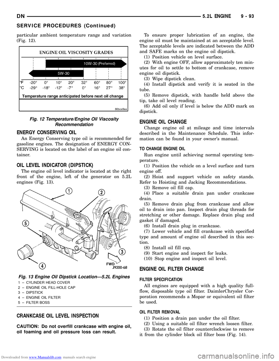
Downloaded from www.Manualslib.com manuals search engine particular ambient temperature range and variation
(Fig. 12).
ENERGY CONSERVING OIL
An Energy Conserving type oil is recommended for
gasoline engines. The designation of ENERGY CON-
SERVING is located on the label of an engine oil con-
tainer.
OIL LEVEL INDICATOR (DIPSTICK)
The engine oil level indicator is located at the right
front of the engine, left of the generator on 5.2L
engines (Fig. 13).
CRANKCASE OIL LEVEL INSPECTION
CAUTION: Do not overfill crankcase with engine oil,
oil foaming and oil pressure loss can result.To ensure proper lubrication of an engine, the
engine oil must be maintained at an acceptable level.
The acceptable levels are indicated between the ADD
and SAFE marks on the engine oil dipstick.
(1) Position vehicle on level surface.
(2) With engine OFF, allow approximately ten min-
utes for oil to settle to bottom of crankcase, remove
engine oil dipstick.
(3) Wipe dipstick clean.
(4) Install dipstick and verify it is seated in the
tube.
(5) Remove dipstick, with handle held above the
tip, take oil level reading.
(6) Add oil only if level is below the ADD mark on
dipstick.
ENGINE OIL CHANGE
Change engine oil at mileage and time intervals
described in the Maintenance Schedule. This infor-
mation can be found in your owner's manual.
TO CHANGE ENGINE OIL
Run engine until achieving normal operating tem-
perature.
(1) Position the vehicle on a level surface and turn
engine off.
(2) Hoist and support vehicle on safety stands.
Refer to Hoisting and Jacking Recommendations.
(3) Remove oil fill cap.
(4) Place a suitable drain pan under crankcase
drain.
(5) Remove drain plug from crankcase and allow
oil to drain into pan. Inspect drain plug threads for
stretching or other damage. Replace drain plug and
gasket if damaged.
(6) Install drain plug in crankcase.
(7) Lower vehicle and fill crankcase with specified
type and amount of engine oil described in this sec-
tion.
(8) Install oil fill cap.
(9) Start engine and inspect for leaks.
(10) Stop engine and inspect oil level.
ENGINE OIL FILTER CHANGE
FILTER SPECIFICATION
All engines are equipped with a high quality full-
flow, disposable type oil filter. DaimlerChrysler Cor-
poration recommends a Mopar or equivalent oil filter
be used.
OIL FILTER REMOVAL
(1) Position a drain pan under the oil filter.
(2) Using a suitable oil filter wrench loosen filter.
(3) Rotate the oil filter counterclockwise to remove
it from the cylinder block oil filter boss (Fig. 14).
Fig. 12 Temperature/Engine Oil Viscosity
Recommendation
Fig. 13 Engine Oil Dipstick LocationÐ5.2L Engines
1 ± CYLINDER HEAD COVER
2 ± ENGINE OIL FILL-HOLE CAP
3 ± DIPSTICK
4 ± ENGINE OIL FILTER
5 ± FILTER BOSS
DN5.2L ENGINE 9 - 93
SERVICE PROCEDURES (Continued)
Page 102 of 193
Downloaded from www.Manualslib.com manuals search engine ENGINE MOUNTÐREAR
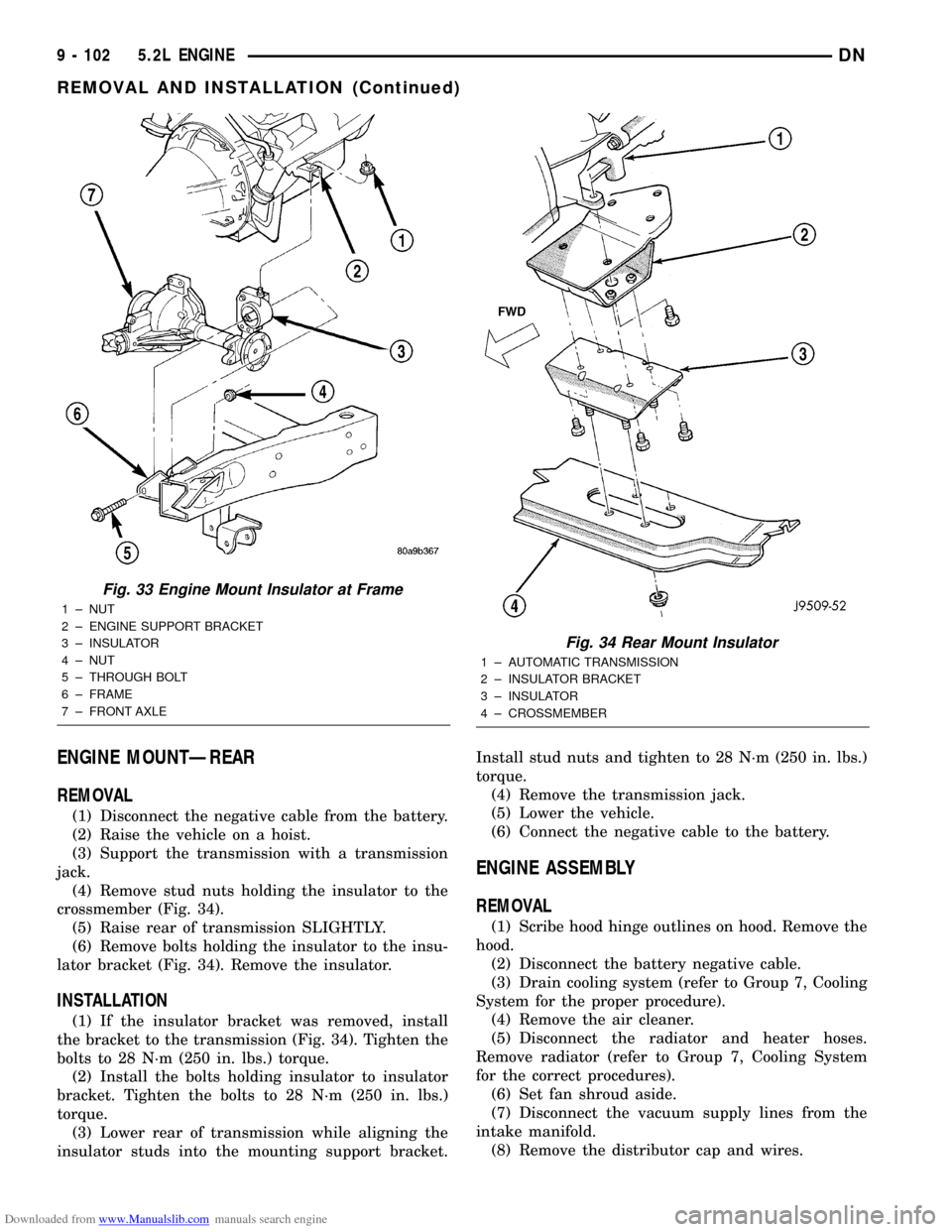
REMOVAL
(1) Disconnect the negative cable from the battery.
(2) Raise the vehicle on a hoist.
(3) Support the transmission with a transmission
jack.
(4) Remove stud nuts holding the insulator to the
crossmember (Fig. 34).
(5) Raise rear of transmission SLIGHTLY.
(6) Remove bolts holding the insulator to the insu-
lator bracket (Fig. 34). Remove the insulator.
INSTALLATION
(1) If the insulator bracket was removed, install
the bracket to the transmission (Fig. 34). Tighten the
bolts to 28 N´m (250 in. lbs.) torque.
(2) Install the bolts holding insulator to insulator
bracket. Tighten the bolts to 28 N´m (250 in. lbs.)
torque.
(3) Lower rear of transmission while aligning the
insulator studs into the mounting support bracket.Install stud nuts and tighten to 28 N´m (250 in. lbs.)
torque.
(4) Remove the transmission jack.
(5) Lower the vehicle.
(6) Connect the negative cable to the battery.
ENGINE ASSEMBLY
REMOVAL
(1) Scribe hood hinge outlines on hood. Remove the
hood.
(2) Disconnect the battery negative cable.
(3) Drain cooling system (refer to Group 7, Cooling
System for the proper procedure).
(4) Remove the air cleaner.
(5) Disconnect the radiator and heater hoses.
Remove radiator (refer to Group 7, Cooling System
for the correct procedures).
(6) Set fan shroud aside.
(7) Disconnect the vacuum supply lines from the
intake manifold.
(8) Remove the distributor cap and wires.
Fig. 33 Engine Mount Insulator at Frame
1 ± NUT
2 ± ENGINE SUPPORT BRACKET
3 ± INSULATOR
4 ± NUT
5 ± THROUGH BOLT
6 ± FRAME
7 ± FRONT AXLE
Fig. 34 Rear Mount Insulator
1 ± AUTOMATIC TRANSMISSION
2 ± INSULATOR BRACKET
3 ± INSULATOR
4 ± CROSSMEMBER
9 - 102 5.2L ENGINEDN
REMOVAL AND INSTALLATION (Continued)
Page 115 of 193
Downloaded from www.Manualslib.com manuals search engine After the distributor has been installed, its rota-
tional position must be set using theSET SYNC
mode of the DRB scan tool. Refer to Checking Dis-
tributor Position following the Distributor Installa-
tion section in Group 8D, Ignition system.
Do not attempt to adjust ignition timing by
rotating the distributor. It has no effect on igni-
tion timing. Adjusting distributor position will
effect fuel synchronization only.
OIL PAN
REMOVAL
2WD
(1) Disconnect the negative cable from the battery.
(2) Remove air cleaner assembly.
(3) Remove engine oil dipstick.
(4) Disconnect distributor cap and position away
from cowl.
(5) Remove the fan shroud. Refer to COOLING
SYSTEM.
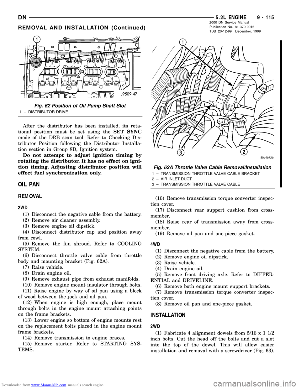
(6) Disconnect throttle valve cable from throttle
body and mounting bracket (Fig. 62A).
(7) Raise vehicle.
(8) Drain engine oil.
(9) Remove exhaust pipe from exhaust manifolds.
(10) Remove engine mount insulator through bolts.
(11) Raise engine by way of oil pan using a block
of wood between the jack and oil pan.
(12) When engine is high enough, place mount
through bolts in the engine mount attaching points
on the frame brackets.
(13) Lower engine so bottom of engine mounts rest
on the replacement bolts placed in the engine mount
frame brackets.
(14) Remove transmission to engine braces.
(15) Remove starter. Refer to STARTING SYS-
TEMS.(16) Remove transmission torque converter inspec-
tion cover.
(17) Disconnect rear support cushion from cross-
member.
(18) Raise rear of transmission away from cross-
member.
(19) Remove oil pan and one-piece gasket.
4WD
(1) Disconnect the negative cable from the battery.
(2) Remove engine oil dipstick.
(3) Raise vehicle.
(4) Drain engine oil.
(5) Remove front driving axle. Refer to DIFFER-
ENTIAL and DRIVELINE.
(6) Remove both engine mount support brackets.
(7) Remove transmission torque converter inspec-
tion cover.
(8) Remove oil pan and one-piece gasket.
INSTALLATION
2WD
(1) Fabricate 4 alignment dowels from 5/16x11/2
inch bolts. Cut the head off the bolts and cut a slot
into the top of the dowel. This will allow easier
installation and removal with a screwdriver (Fig. 63).
Fig. 62 Position of Oil Pump Shaft Slot
1 ± DISTRIBUTOR DRIVE
Fig. 62A Throttle Valve Cable Removal/Installation
1 ± TRANSMISSION THROTTLE VALVE CABLE BRACKET
2 ± AIR INLET DUCT
3 ± TRANSMISSION THROTTLE VALVE CABLE
DN5.2L ENGINE 9 - 115
REMOVAL AND INSTALLATION (Continued)
2000 DN Service Manual
Publication No. 81-370-0016
TSB 26-12-99 December, 1999