lamp DODGE DURANGO 1999 1.G Workshop Manual
[x] Cancel search | Manufacturer: DODGE, Model Year: 1999, Model line: DURANGO, Model: DODGE DURANGO 1999 1.GPages: 193, PDF Size: 5.65 MB
Page 34 of 193

Downloaded from www.Manualslib.com manuals search engine (20) Install both breathers. Connect tube to both
crankcase breathers (Fig. 44).
(21) Connect throttle and speed control cables.
(22) Install throttle body resonator assembly and
air inlet hose. Tighten clamps 4 N´m (35 in. lbs.).
(23) Raise vehicle.
(24) Install transmission to engine mounting bolts.
Tighten the bolts to 41 N´m (30 ft. lbs.).
(25) Install torque converter bolts (Automatic
Transmission Only).
(26) Connect crankshaft position sensor (Fig. 43).
(27)4X4 vehiclesPosition and install the axle
isolator bracket onto the axle, transmission and
engine block. Tighten bolts to specification. Refer to
Specifications in this section.
(28) Install starter.
CAUTION: The structural cover requires a specific
torque sequence. Failure to follow this sequence
may cause severe damage to the cover.(29) Install structural cover. Refer to Structural
Cover in this section.
(30) Install exhaust crossover pipe.
(31) Install engine block heater power cable, If
equipped.
(32)4X4 vehiclesConnect axle vent tube to left
side engine mount.
(33) Lower vehicle.
(34) Check and fill engine oil.
(35) Recharge the A/C system.
(36) Refill the engine cooling system. Refer to
COOLING SYSTEM.
(37) Install the battery tray and battery.
(38) Connect the battery positive and negative
cables.
(39) Start the engine and check for leaks.
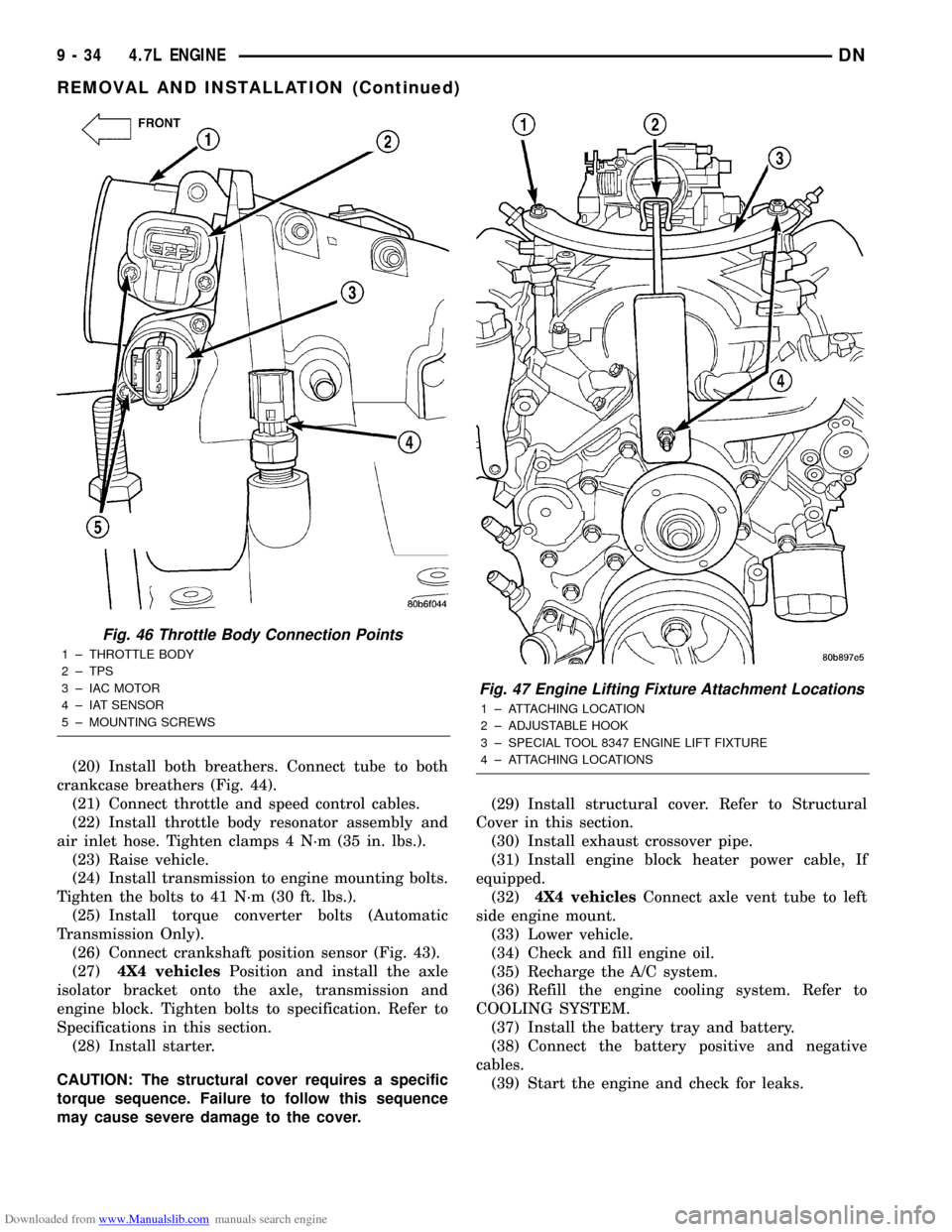
Fig. 46 Throttle Body Connection Points
1 ± THROTTLE BODY
2 ± TPS
3 ± IAC MOTOR
4 ± IAT SENSOR
5 ± MOUNTING SCREWS
Fig. 47 Engine Lifting Fixture Attachment Locations
1 ± ATTACHING LOCATION
2 ± ADJUSTABLE HOOK
3 ± SPECIAL TOOL 8347 ENGINE LIFT FIXTURE
4 ± ATTACHING LOCATIONS
9 - 34 4.7L ENGINEDN
REMOVAL AND INSTALLATION (Continued)
Page 124 of 193

Downloaded from www.Manualslib.com manuals search engine (2) Measure the concentricity of valve seat using a
dial indicator. Total runout should not exceed 0.051
mm (0.002 inch) total indicator reading.
(3) Inspect the valve seat with Prussian blue to
determine where the valve contacts the seat. To do
this, coat valve seat LIGHTLY with Prussian blue
then set valve in place. Rotate the valve with light
pressure. If the blue is transferred to the center of
valve face, contact is satisfactory. If the blue is trans-
ferred to the top edge of valve face, lower valve seat
with a 15É stone. If the blue is transferred to bottom
edge of valve face raise valve seat with a 60É stone.
(4) When seat is properly positioned the width of
intake seats should be 1.016-1.524 mm (0.040-0.060
inch). The width of the exhaust seats should be
1.524-2.032 mm (0.060-0.080 inch).
VALVE SPRING INSPECTION
Whenever valves have been removed for inspection,
reconditioning or replacement, valve springs should
be tested. As an example the compression length of
the spring to be tested is 1-5/16 inch. Turn table of
Universals Valve Spring Tester Tool until surface is
in line with the 1-5/16 inch mark on the threaded
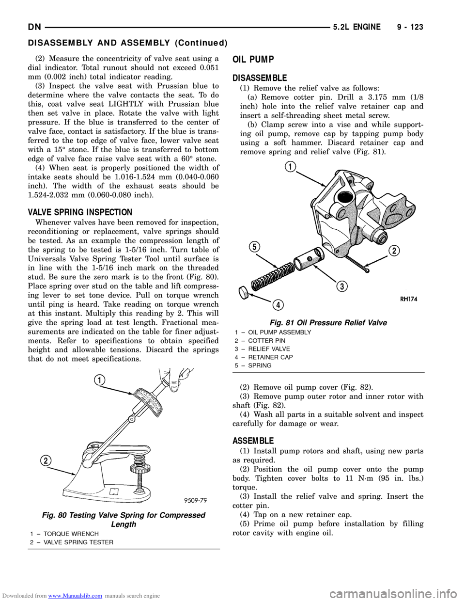
stud. Be sure the zero mark is to the front (Fig. 80).
Place spring over stud on the table and lift compress-
ing lever to set tone device. Pull on torque wrench
until ping is heard. Take reading on torque wrench
at this instant. Multiply this reading by 2. This will
give the spring load at test length. Fractional mea-
surements are indicated on the table for finer adjust-
ments. Refer to specifications to obtain specified
height and allowable tensions. Discard the springs
that do not meet specifications.
OIL PUMP
DISASSEMBLE
(1) Remove the relief valve as follows:
(a) Remove cotter pin. Drill a 3.175 mm (1/8
inch) hole into the relief valve retainer cap and
insert a self-threading sheet metal screw.
(b) Clamp screw into a vise and while support-
ing oil pump, remove cap by tapping pump body
using a soft hammer. Discard retainer cap and
remove spring and relief valve (Fig. 81).
(2) Remove oil pump cover (Fig. 82).
(3) Remove pump outer rotor and inner rotor with
shaft (Fig. 82).
(4) Wash all parts in a suitable solvent and inspect
carefully for damage or wear.
ASSEMBLE
(1) Install pump rotors and shaft, using new parts
as required.
(2) Position the oil pump cover onto the pump
body. Tighten cover bolts to 11 N´m (95 in. lbs.)
torque.
(3) Install the relief valve and spring. Insert the
cotter pin.
(4) Tap on a new retainer cap.
(5) Prime oil pump before installation by filling
rotor cavity with engine oil.
Fig. 80 Testing Valve Spring for Compressed
Length
1 ± TORQUE WRENCH
2 ± VALVE SPRING TESTER
Fig. 81 Oil Pressure Relief Valve
1 ± OIL PUMP ASSEMBLY
2 ± COTTER PIN
3 ± RELIEF VALVE
4 ± RETAINER CAP
5 ± SPRING
DN5.2L ENGINE 9 - 123
DISASSEMBLY AND ASSEMBLY (Continued)
Page 182 of 193

Downloaded from www.Manualslib.com manuals search engine INSTALLATION
Thoroughly clean inside of cup plug hole in cylin-
der block or head. Be sure to remove old sealer.
Be certain the new plug is cleaned of all oil or
grease.
(1) Coat edges of plug and core hole with Mopart
Gasket Maker, or equivalent.
CAUTION: DO NOT drive cup plug into the casting,
as restricted coolant flow can result and cause seri-
ous engine problems.
(2) Using proper plug drive, drive cup plug into
hole. The sharp edge of the plug should be at least
0.50 mm (0.020 in.) inside the lead-in chamfer.
(3) It is not necessary to wait for curing of the
sealant. The cooling system can be filled and the
vehicle placed in service immediately.
DISASSEMBLY AND ASSEMBLY
OIL PUMP
DISASSEMBLE
(1) Remove the relief valve as follows:
(a) Remove cotter pin. Drill a 3.175 mm (1/8
inch) hole into the relief valve retainer cap and
insert a self-threading sheet metal screw.
(b) Clamp screw into a vise and while support-
ing oil pump, remove cap by tapping pump body
using a soft hammer. Discard retainer cap and
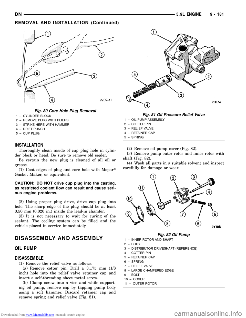
remove spring and relief valve (Fig. 81).(2) Remove oil pump cover (Fig. 82).
(3) Remove pump outer rotor and inner rotor with
shaft (Fig. 82).
(4) Wash all parts in a suitable solvent and inspect
carefully for damage or wear.
Fig. 80 Core Hole Plug Removal
1 ± CYLINDER BLOCK
2 ± REMOVE PLUG WITH PLIERS
3 ± STRIKE HERE WITH HAMMER
4 ± DRIFT PUNCH
5 ± CUP PLUGFig. 81 Oil Pressure Relief Valve
1 ± OIL PUMP ASSEMBLY
2 ± COTTER PIN
3 ± RELIEF VALVE
4 ± RETAINER CAP
5 ± SPRING
Fig. 82 Oil Pump
1 ± INNER ROTOR AND SHAFT
2 ± BODY
3 ± DISTRIBUTOR DRIVESHAFT (REFERENCE)
4 ± COTTER PIN
5 ± RETAINER CAP
6 ± SPRING
7 ± RELIEF VALVE
8 ± LARGE CHAMFERED EDGE
9 ± BOLT
10 ± COVER
11 ± OUTER ROTOR
DN5.9L ENGINE 9 - 181
REMOVAL AND INSTALLATION (Continued)