run flat DODGE DURANGO 1999 1.G Workshop Manual
[x] Cancel search | Manufacturer: DODGE, Model Year: 1999, Model line: DURANGO, Model: DODGE DURANGO 1999 1.GPages: 193, PDF Size: 5.65 MB
Page 15 of 193

Downloaded from www.Manualslib.com manuals search engine CHECKING ENGINE OIL PRESSURE
(1) Remove oil pressure sending unit (Fig. 3) and
install gauge assembly C-3292.
(2) Run engine until thermostat opens.
(3) Oil Pressure:
²Curb IdleÐ25 Kpa (4 psi) minimum
²3000 rpmÐ170 - 550 KPa (25 - 80 psi)
(4) If oil pressure is 0 at idle, shut off engine.
Check for a clogged oil pick-up screen or a pressure
relief valve stuck open.
SERVICE PROCEDURES
FORM-IN-PLACE GASKETS
There are several places where form-in-place gas-
kets are used on the engine.DO NOT use form-in-
place gasket material unless specified.Care
must be taken when applying form-in-place gaskets.
Bead size, continuity and location are of great impor-
tance. Too thin a bead can result in leakage while too
much can result in spill-over. A continuous bead of
the proper width is essential to obtain a leak-free
joint.
Two types of form-in-place gasket materials are
used in the engine area (Mopar Silicone Rubber
Adhesive Sealant and Mopar Gasket Maker). Eachhave different properties and cannot be used inter-
changeably.
MOPAR SILICONE RUBBER ADHESIVE SEALANT
Mopar Silicone Rubber Adhesive Sealant, normally
black in color, is available in 3 ounce tubes. Moisture
in the air causes the sealant material to cure. This
material is normally used on flexible metal flanges.
It has a shelf life of a year and will not properly cure
if over aged. Always inspect the package for the expi-
ration date before use.
MOPAR GASKET MAKER
Mopar Gasket Maker, normally red in color, is
available in 6 cc tubes. This anaerobic type gasket
material cures in the absence of air when squeezed
between smooth machined metallic surfaces. It will
not cure if left in the uncovered tube. DO NOT use
on flexible metal flanges.
SURFACE PREPARATION
Parts assembled with form-in-place gaskets may be
disassembled without unusual effort. In some
instances, it may be necessary to lightly tap the part
with a mallet or other suitable tool to break the seal
between the mating surfaces. A flat gasket scraper
may also be lightly tapped into the joint but care
must be taken not to damage the mating surfaces.
Scrape or wire brush all gasket surfaces to remove
all loose material. Inspect stamped parts to ensure
gasket rails are flat. Flatten rails with a hammer on
a flat plate, if required. Gasket surfaces must be free
of oil and dirt. Make sure the old gasket material is
removed from blind attaching holes.
GASKET APPLICATION
Assembling parts using a form-in-place gasket
requires care.
Mopar Silicone Rubber Adhesive Sealant should be
applied in a continuous bead approximately 3 mm
(0.12 inch) in diameter. All mounting holes must be
circled. For corner sealing,a3or6mm(1/8 or 1/4
inch) drop is placed in the center of the gasket con-
tact area. Uncured sealant may be removed with a
shop towel. Components should be torqued in place
while the sealant is still wet to the touch (within 10
minutes). The use of a locating dowel is recom-
mended during assembly to prevent smearing the
material off location.
Mopar Gasket Maker should be applied sparingly
to one gasket surface. The sealant diameter should
be 1.00 mm (0.04 inch) or less. Be certain the mate-
rial surrounds each mounting hole. Excess material
can easily be wiped off. Components should be
torqued in place within 15 minutes. The use of a
Fig. 3 Oil Pressure Sending Unit
1 ± BELT
2 ± OIL PRESSURE SENSOR
3 ± OIL FILTER
4 ± ELEC. CONNECTOR
DN4.7L ENGINE 9 - 15
DIAGNOSIS AND TESTING (Continued)
Page 80 of 193

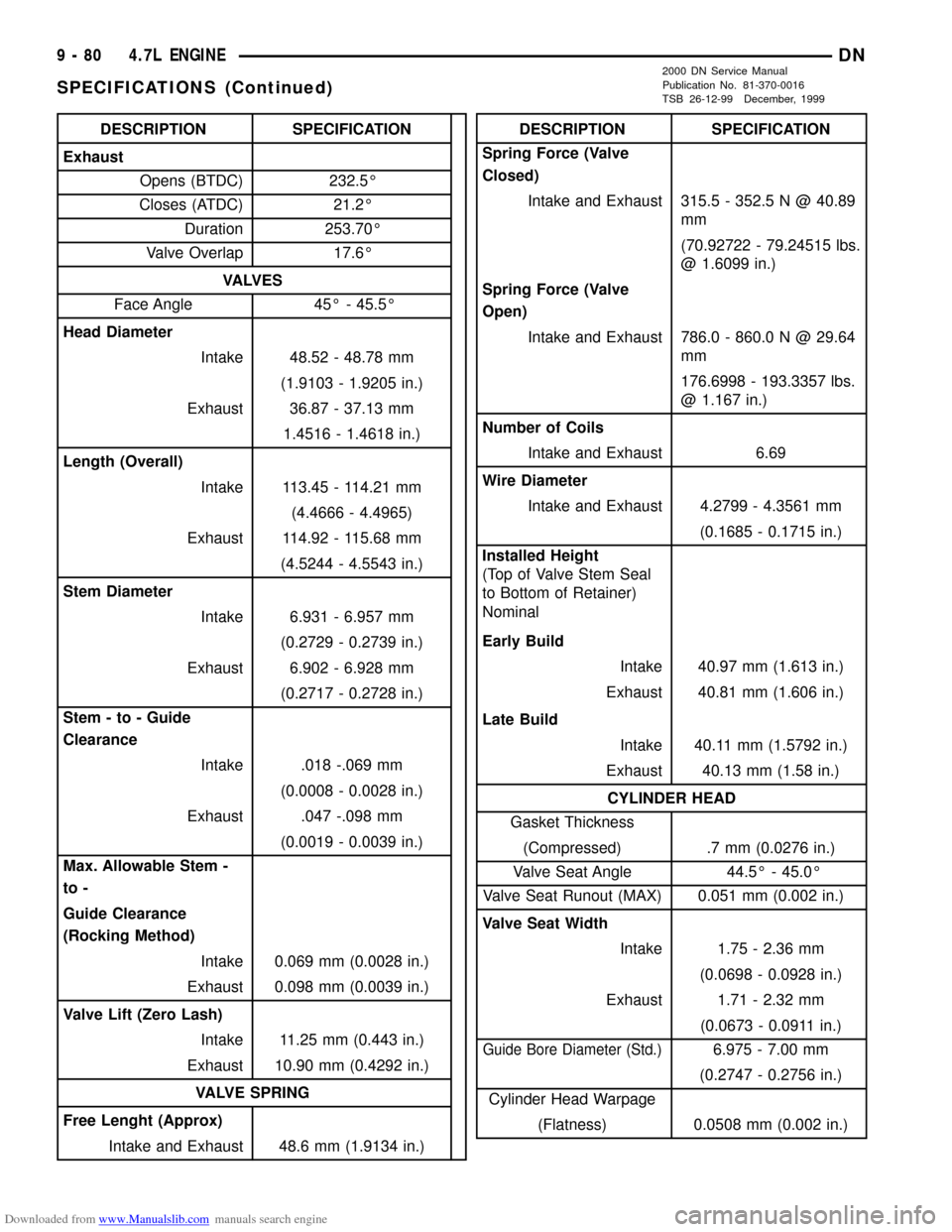
Downloaded from www.Manualslib.com manuals search engine DESCRIPTION SPECIFICATION
Exhaust
Opens (BTDC) 232.5É
Closes (ATDC) 21.2É
Duration 253.70É
Valve Overlap 17.6É
VA LV E S
Face Angle 45É - 45.5É
Head Diameter
Intake 48.52 - 48.78 mm
(1.9103 - 1.9205 in.)
Exhaust 36.87 - 37.13 mm
1.4516 - 1.4618 in.)
Length (Overall)
Intake 113.45 - 114.21 mm
(4.4666 - 4.4965)
Exhaust 114.92 - 115.68 mm
(4.5244 - 4.5543 in.)
Stem Diameter
Intake 6.931 - 6.957 mm
(0.2729 - 0.2739 in.)
Exhaust 6.902 - 6.928 mm
(0.2717 - 0.2728 in.)
Stem - to - Guide
Clearance
Intake .018 -.069 mm
(0.0008 - 0.0028 in.)
Exhaust .047 -.098 mm
(0.0019 - 0.0039 in.)
Max. Allowable Stem -
to -
Guide Clearance
(Rocking Method)
Intake 0.069 mm (0.0028 in.)
Exhaust 0.098 mm (0.0039 in.)
Valve Lift (Zero Lash)
Intake 11.25 mm (0.443 in.)
Exhaust 10.90 mm (0.4292 in.)
VALVE SPRING
Free Lenght (Approx)
Intake and Exhaust 48.6 mm (1.9134 in.)DESCRIPTION SPECIFICATION
Spring Force (Valve
Closed)
Intake and Exhaust 315.5 - 352.5 N @ 40.89
mm
(70.92722 - 79.24515 lbs.
@ 1.6099 in.)
Spring Force (Valve
Open)
Intake and Exhaust 786.0 - 860.0 N @ 29.64
mm
176.6998 - 193.3357 lbs.
@ 1.167 in.)
Number of Coils
Intake and Exhaust 6.69
Wire Diameter
Intake and Exhaust 4.2799 - 4.3561 mm
(0.1685 - 0.1715 in.)
Installed Height
(Top of Valve Stem Seal
to Bottom of Retainer)
Nominal
Early Build
Intake 40.97 mm (1.613 in.)
Exhaust 40.81 mm (1.606 in.)
Late Build
Intake 40.11 mm (1.5792 in.)
Exhaust 40.13 mm (1.58 in.)
CYLINDER HEAD
Gasket Thickness
(Compressed) .7 mm (0.0276 in.)
Valve Seat Angle 44.5É - 45.0É
Valve Seat Runout (MAX) 0.051 mm (0.002 in.)
Valve Seat Width
Intake 1.75 - 2.36 mm
(0.0698 - 0.0928 in.)
Exhaust 1.71 - 2.32 mm
(0.0673 - 0.0911 in.)
Guide Bore Diameter (Std.)6.975 - 7.00 mm
(0.2747 - 0.2756 in.)
Cylinder Head Warpage
(Flatness) 0.0508 mm (0.002 in.)
9 - 80 4.7L ENGINEDN
SPECIFICATIONS (Continued)
2000 DN Service Manual
Publication No. 81-370-0016
TSB 26-12-99 December, 1999
Page 81 of 193

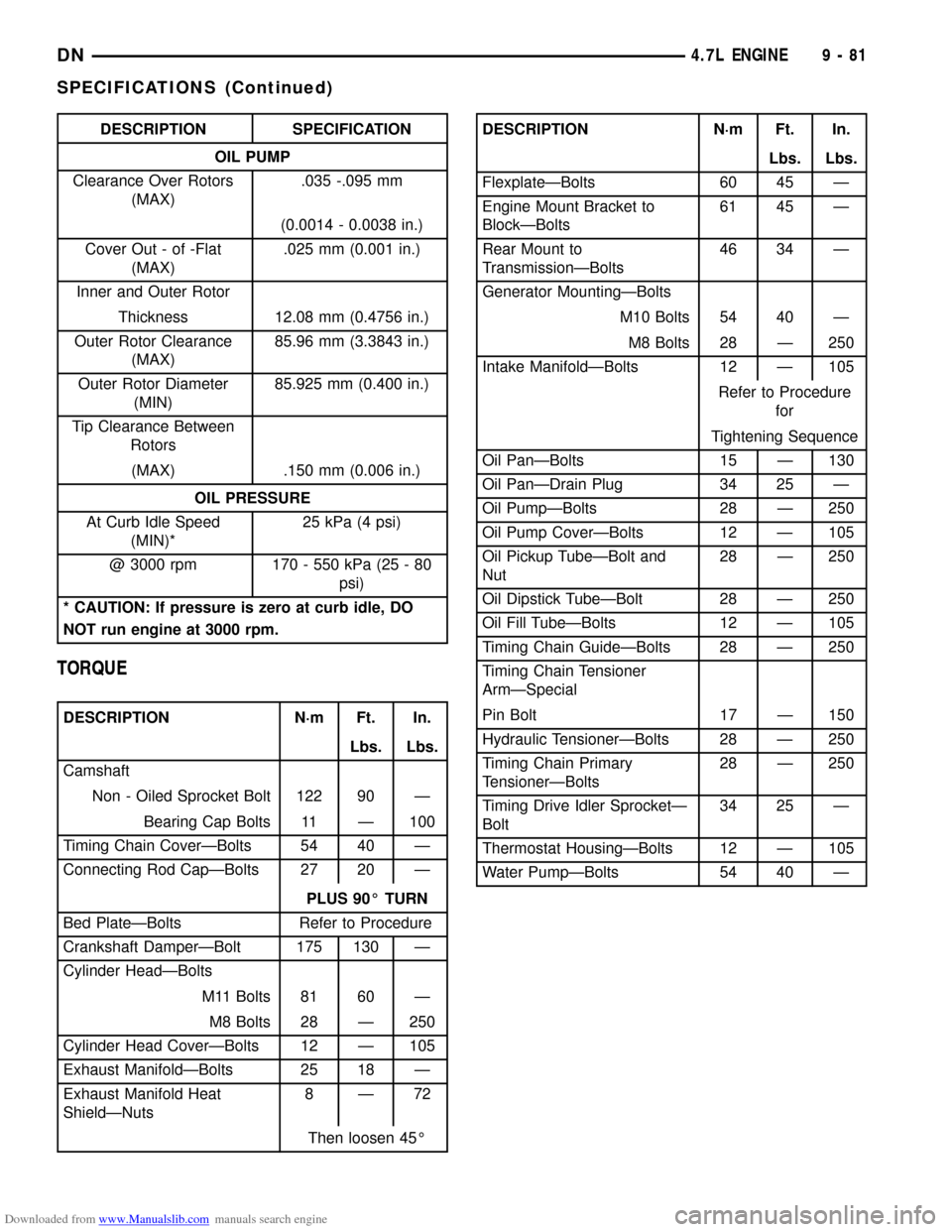
Downloaded from www.Manualslib.com manuals search engine DESCRIPTION SPECIFICATION
OIL PUMP
Clearance Over Rotors
(MAX).035 -.095 mm
(0.0014 - 0.0038 in.)
Cover Out - of -Flat
(MAX).025 mm (0.001 in.)
Inner and Outer Rotor
Thickness 12.08 mm (0.4756 in.)
Outer Rotor Clearance
(MAX)85.96 mm (3.3843 in.)
Outer Rotor Diameter
(MIN)85.925 mm (0.400 in.)
Tip Clearance Between
Rotors
(MAX) .150 mm (0.006 in.)
OIL PRESSURE
At Curb Idle Speed
(MIN)*25 kPa (4 psi)
@ 3000 rpm 170 - 550 kPa (25 - 80
psi)
* CAUTION: If pressure is zero at curb idle, DO
NOT run engine at 3000 rpm.
TORQUE
DESCRIPTION N´m Ft. In.
Lbs. Lbs.
Camshaft
Non - Oiled Sprocket Bolt 122 90 Ð
Bearing Cap Bolts 11 Ð 100
Timing Chain CoverÐBolts 54 40 Ð
Connecting Rod CapÐBolts 27 20 Ð
PLUS 90É TURN
Bed PlateÐBolts Refer to Procedure
Crankshaft DamperÐBolt 175 130 Ð
Cylinder HeadÐBolts
M11 Bolts 81 60 Ð
M8 Bolts 28 Ð 250
Cylinder Head CoverÐBolts 12 Ð 105
Exhaust ManifoldÐBolts 25 18 Ð
Exhaust Manifold Heat
ShieldÐNuts8Ð72
Then loosen 45É
DESCRIPTION N´m Ft. In.
Lbs. Lbs.
FlexplateÐBolts 60 45 Ð
Engine Mount Bracket to
BlockÐBolts61 45 Ð
Rear Mount to
TransmissionÐBolts46 34 Ð
Generator MountingÐBolts
M10 Bolts 54 40 Ð
M8 Bolts 28 Ð 250
Intake ManifoldÐBolts 12 Ð 105
Refer to Procedure
for
Tightening Sequence
Oil PanÐBolts 15 Ð 130
Oil PanÐDrain Plug 34 25 Ð
Oil PumpÐBolts 28 Ð 250
Oil Pump CoverÐBolts 12 Ð 105
Oil Pickup TubeÐBolt and
Nut28 Ð 250
Oil Dipstick TubeÐBolt 28 Ð 250
Oil Fill TubeÐBolts 12 Ð 105
Timing Chain GuideÐBolts 28 Ð 250
Timing Chain Tensioner
ArmÐSpecial
Pin Bolt 17 Ð 150
Hydraulic TensionerÐBolts 28 Ð 250
Timing Chain Primary
TensionerÐBolts28 Ð 250
Timing Drive Idler SprocketÐ
Bolt34 25 Ð
Thermostat HousingÐBolts 12 Ð 105
Water PumpÐBolts 54 40 Ð
DN4.7L ENGINE 9 - 81
SPECIFICATIONS (Continued)
Page 188 of 193

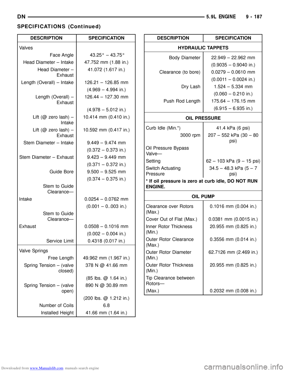
Downloaded from www.Manualslib.com manuals search engine DESCRIPTION SPECIFICATION
Valves
Face Angle 43.25É ± 43.75É
Head Diameter ± Intake 47.752 mm (1.88 in.)
Head Diameter ±
Exhaust41.072 (1.617 in.)
Length (Overall) ± Intake 126.21 ± 126.85 mm
(4.969 ± 4.994 in.)
Length (Overall) ±
Exhaust126.44 ± 127.30 mm
(4.978 ± 5.012 in.)
Lift (@ zero lash) ±
Intake10.414 mm (0.410 in.)
Lift (@ zero lash) ±
Exhaust10.592 mm (0.417 in.)
Stem Diameter ± Intake 9.449 ± 9.474 mm
(0.372 ± 0.373 in.)
Stem Diameter ± Exhaust 9.423 ± 9.449 mm
(0.371 ± 0.372 in.)
Guide Bore 9.500 ± 9.525 mm
(0.374 ± 0.375 in.)
Stem to Guide
ClearanceÐ
Intake 0.0254 ± 0.0762 mm
(0.001 ± 0..003 in.)
Stem to Guide
ClearanceÐ
Exhaust 0.0508 ± 0.1016 mm
(0.002 ± 0.004 in.)
Service Limit 0.4318 (0.017 in.)
Valve Springs
Free Length 49.962 mm (1.967 in.)
Spring Tension ± (valve
closed)378 N @ 41.66 mm
(85 lbs. @ 1.64 in.)
Spring Tension ± (valve
open)890 N @ 30.89 mm
(200 lbs. @ 1.212 in.)
Number of Coils 6.8
Installed Height 41.66 mm (1.64 in.)DESCRIPTION SPECIFICATION
HYDRAULIC TAPPETS
Body Diameter 22.949 ± 22.962 mm
(0.9035 ± 0.9040 in.)
Clearance (to bore) 0.0279 ± 0.0610 mm
(0.0011 ± 0.0024 in.)
Dry Lash 1.524 ± 5.334 mm
(0.060 ± 0.210 in.)
Push Rod Length 175.64 ± 176.15 mm
(6.915 ± 6.935 in.)
OIL PRESSURE
Curb Idle (Min.*) 41.4 kPa (6 psi)
3000 rpm 207 ± 552 kPa (30 ± 80
psi)
Oil Pressure Bypass
ValveÐ
Setting 62 ± 103 kPa (9 ± 15 psi)
Switch Actuating
Pressure34.5 ± 48.3 kPa (5 ± 7
psi)
* If oil pressure is zero at curb idle, DO NOT RUN
ENGINE.
OIL PUMP
Clearance over Rotors
(Max.)0.1016 mm (0.004 in.)
Cover Out of Flat (Max.) 0.0381 mm (0.0015 in.)
Inner Rotor Thickness
(Min.)20.955 mm (0.825 in.)
Outer Rotor Clearance
(Max.)0.3556 mm (0.014 in.)
Outer Rotor Diameter
(Min.)62.7126 mm (2.469 in.)
Outer Rotor Thickness
(Min.)20.955 mm (0.825 in.)
Tip Clearance between
RotorsÐ
(Max.) 0.2032 mm (0.008 in.)
DN5.9L ENGINE 9 - 187
SPECIFICATIONS (Continued)