wire DODGE DURANGO 1999 1.G Workshop Manual
[x] Cancel search | Manufacturer: DODGE, Model Year: 1999, Model line: DURANGO, Model: DODGE DURANGO 1999 1.GPages: 193, PDF Size: 5.65 MB
Page 8 of 193
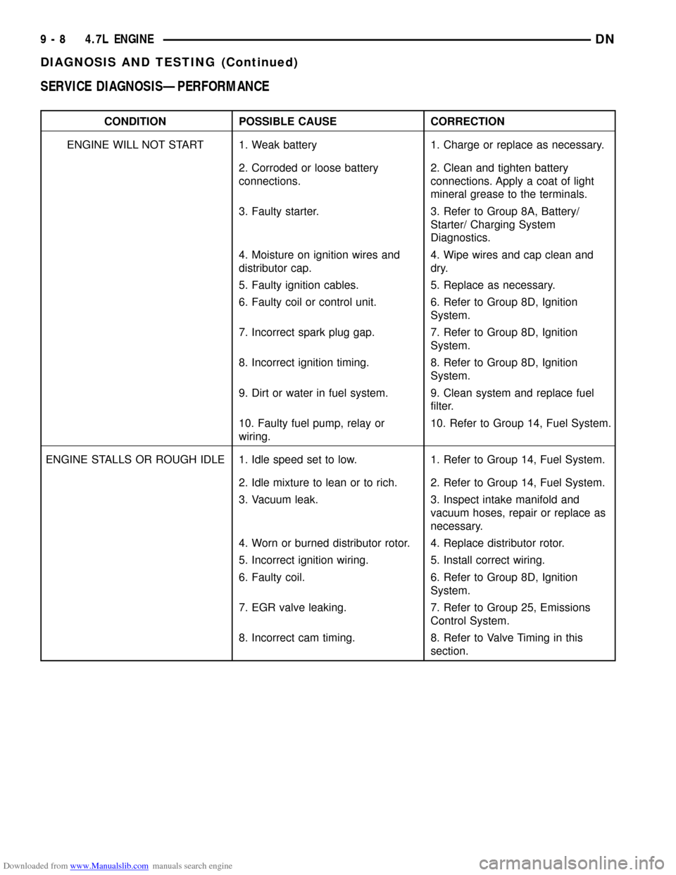
Downloaded from www.Manualslib.com manuals search engine SERVICE DIAGNOSISÐPERFORMANCE
CONDITION POSSIBLE CAUSE CORRECTION
ENGINE WILL NOT START 1. Weak battery 1. Charge or replace as necessary.
2. Corroded or loose battery
connections.2. Clean and tighten battery
connections. Apply a coat of light
mineral grease to the terminals.
3. Faulty starter. 3. Refer to Group 8A, Battery/
Starter/ Charging System
Diagnostics.
4. Moisture on ignition wires and
distributor cap.4. Wipe wires and cap clean and
dry.
5. Faulty ignition cables. 5. Replace as necessary.
6. Faulty coil or control unit. 6. Refer to Group 8D, Ignition
System.
7. Incorrect spark plug gap. 7. Refer to Group 8D, Ignition
System.
8. Incorrect ignition timing. 8. Refer to Group 8D, Ignition
System.
9. Dirt or water in fuel system. 9. Clean system and replace fuel
filter.
10. Faulty fuel pump, relay or
wiring.10. Refer to Group 14, Fuel System.
ENGINE STALLS OR ROUGH IDLE 1. Idle speed set to low. 1. Refer to Group 14, Fuel System.
2. Idle mixture to lean or to rich. 2. Refer to Group 14, Fuel System.
3. Vacuum leak. 3. Inspect intake manifold and
vacuum hoses, repair or replace as
necessary.
4. Worn or burned distributor rotor. 4. Replace distributor rotor.
5. Incorrect ignition wiring. 5. Install correct wiring.
6. Faulty coil. 6. Refer to Group 8D, Ignition
System.
7. EGR valve leaking. 7. Refer to Group 25, Emissions
Control System.
8. Incorrect cam timing. 8. Refer to Valve Timing in this
section.
9 - 8 4.7L ENGINEDN
DIAGNOSIS AND TESTING (Continued)
Page 15 of 193
Downloaded from www.Manualslib.com manuals search engine CHECKING ENGINE OIL PRESSURE
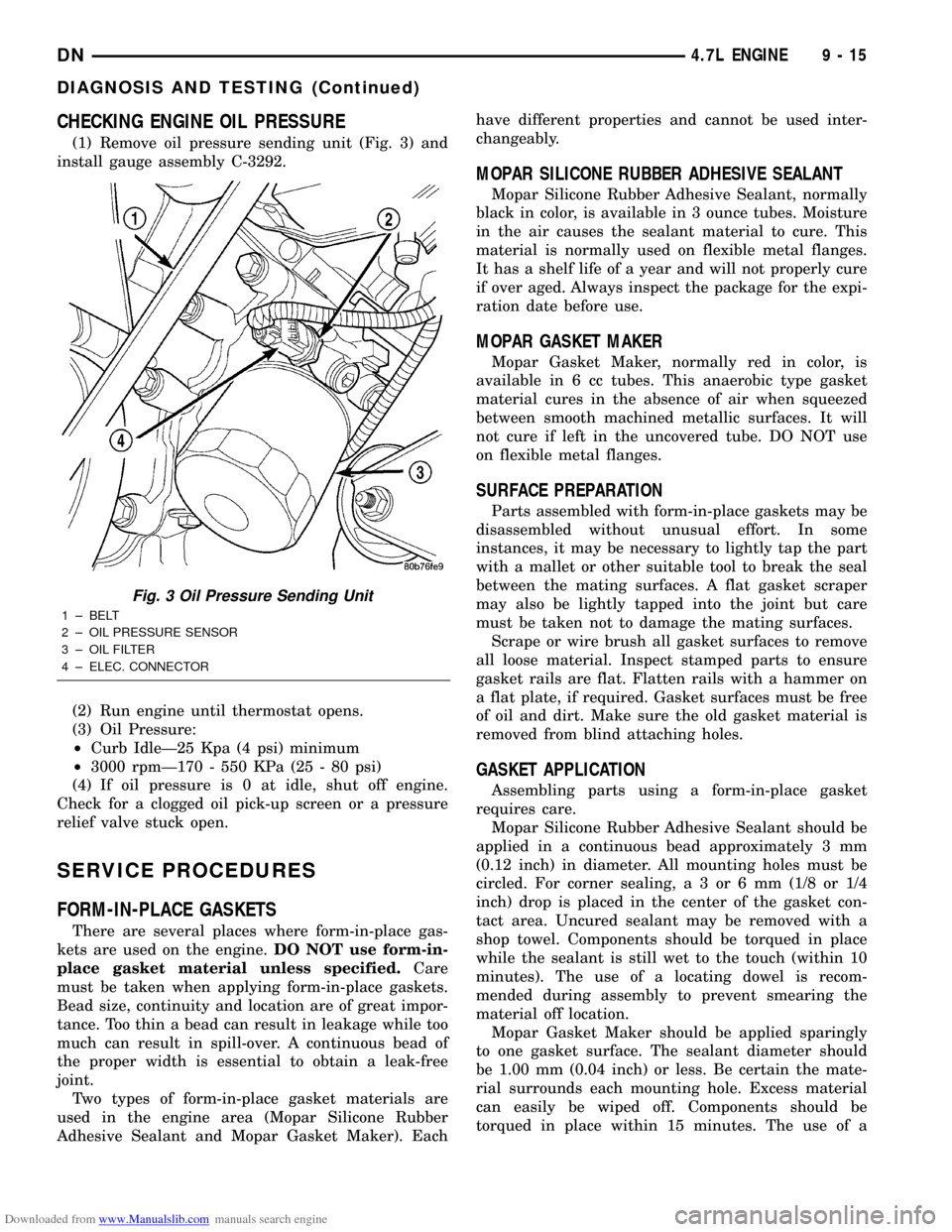
(1) Remove oil pressure sending unit (Fig. 3) and
install gauge assembly C-3292.
(2) Run engine until thermostat opens.
(3) Oil Pressure:
²Curb IdleÐ25 Kpa (4 psi) minimum
²3000 rpmÐ170 - 550 KPa (25 - 80 psi)
(4) If oil pressure is 0 at idle, shut off engine.
Check for a clogged oil pick-up screen or a pressure
relief valve stuck open.
SERVICE PROCEDURES
FORM-IN-PLACE GASKETS
There are several places where form-in-place gas-
kets are used on the engine.DO NOT use form-in-
place gasket material unless specified.Care
must be taken when applying form-in-place gaskets.
Bead size, continuity and location are of great impor-
tance. Too thin a bead can result in leakage while too
much can result in spill-over. A continuous bead of
the proper width is essential to obtain a leak-free
joint.
Two types of form-in-place gasket materials are
used in the engine area (Mopar Silicone Rubber
Adhesive Sealant and Mopar Gasket Maker). Eachhave different properties and cannot be used inter-
changeably.
MOPAR SILICONE RUBBER ADHESIVE SEALANT
Mopar Silicone Rubber Adhesive Sealant, normally
black in color, is available in 3 ounce tubes. Moisture
in the air causes the sealant material to cure. This
material is normally used on flexible metal flanges.
It has a shelf life of a year and will not properly cure
if over aged. Always inspect the package for the expi-
ration date before use.
MOPAR GASKET MAKER
Mopar Gasket Maker, normally red in color, is
available in 6 cc tubes. This anaerobic type gasket
material cures in the absence of air when squeezed
between smooth machined metallic surfaces. It will
not cure if left in the uncovered tube. DO NOT use
on flexible metal flanges.
SURFACE PREPARATION
Parts assembled with form-in-place gaskets may be
disassembled without unusual effort. In some
instances, it may be necessary to lightly tap the part
with a mallet or other suitable tool to break the seal
between the mating surfaces. A flat gasket scraper
may also be lightly tapped into the joint but care
must be taken not to damage the mating surfaces.
Scrape or wire brush all gasket surfaces to remove
all loose material. Inspect stamped parts to ensure
gasket rails are flat. Flatten rails with a hammer on
a flat plate, if required. Gasket surfaces must be free
of oil and dirt. Make sure the old gasket material is
removed from blind attaching holes.
GASKET APPLICATION
Assembling parts using a form-in-place gasket
requires care.
Mopar Silicone Rubber Adhesive Sealant should be
applied in a continuous bead approximately 3 mm
(0.12 inch) in diameter. All mounting holes must be
circled. For corner sealing,a3or6mm(1/8 or 1/4
inch) drop is placed in the center of the gasket con-
tact area. Uncured sealant may be removed with a
shop towel. Components should be torqued in place
while the sealant is still wet to the touch (within 10
minutes). The use of a locating dowel is recom-
mended during assembly to prevent smearing the
material off location.
Mopar Gasket Maker should be applied sparingly
to one gasket surface. The sealant diameter should
be 1.00 mm (0.04 inch) or less. Be certain the mate-
rial surrounds each mounting hole. Excess material
can easily be wiped off. Components should be
torqued in place within 15 minutes. The use of a
Fig. 3 Oil Pressure Sending Unit
1 ± BELT
2 ± OIL PRESSURE SENSOR
3 ± OIL FILTER
4 ± ELEC. CONNECTOR
DN4.7L ENGINE 9 - 15
DIAGNOSIS AND TESTING (Continued)
Page 38 of 193
Downloaded from www.Manualslib.com manuals search engine (9) Install A/C compressor and fasteners.
(10) Install accessory drive belt.
(11) Install air cleaner assembly, resonator assem-
bly and air inlet hose.
(12) Install battery and connect cables.
(13) Fill cooling system.
LEFT EXHAUST MANIFOLD
REMOVAL
(1) Disconnect negative cable for battery.
(2) Hoist vehicle.
(3) Disconnect exhaust pipe at manifold.
(4) Lower vehicle.
(5) Remove the front two exhaust heat shield
retaining fasteners. Raise vehicle and remove the
fasteners at rear of heat shield.
(6) Remove heat shield (Fig. 53).
(7) Lower vehicle and remove the upper exhaust
manifold retaining bolts (Fig. 53).
(8) Raise vehicle and remove the lower exhaust
manifold retaining bolts (Fig. 53).
(9) Remove exhaust manifold and gasket (Fig. 53).
Manifold is removed from below the engine compart-
ment.
INSTALLATION
(1) Install exhaust manifold and gasket from below
engine compartment.
(2) Install lower exhaust manifold fasteners (Fig.
53). DO NOT tighten until all fasteners are in place.
(3) Lower vehicle and install upper exhaust mani-
fold fasteners (Fig. 53). Tighten all manifold bolts
starting at center and working outward to 25 N´m
(18 ft. lbs.).
CAUTION: Over tightening heat shield fasteners,
may cause shield to distort and/or crack.
(4) Install exhaust manifold heat shield (Fig. 53).
Tighten fasteners to 8 N´m (72 in. lbs.), then loosen
45 degrees.
(5) Connect exhaust pipe to manifold.
(6) Connect negative cable to battery.
CYLINDER HEAD COVER
REMOVAL
LEFT SIDE COVER
(1) Disconnect negative cable from battery.
(2) Remove the resonator assemble and air inlet
hose.
(3) Disconnect injector connectors and un-clip the
injector harness.
(4) Route injector harness in front of cylinder head
cover.(5) Disconnect the left side breather tube and
remove the breather tube.
(6) Remove the cylinder head cover mounting
bolts.
(7) Remove cylinder head cover and gasket.
NOTE: The gasket may be used again, provided no
cuts, tears, or deformation has occurred.
INSTALLATION
CAUTION: Do not use harsh cleaners to clean the
cylinder head covers. Severe damage to covers
may occur.
CAUTION: DO NOT allow other components includ-
ing the wire harness to rest on or against the cylin-
der head cover. Prolonged contact with other
objects may wear a hole in the engine cylinder head
cover.
(1) Clean cylinder head cover and both sealing sur-
faces. Inspect and replace gasket as necessary.
(2) Install cylinder head cover and hand start all
fasteners. Verify that all studs are in the correct loca-
tion shown in (Fig. 54).
(3) Tighten cylinder head cover bolts and double
ended studs to 12 N´m (105 in. lbs.).
(4) Install left side breather and connect breather
tube.
(5) Connect injector electrical connectors and injec-
tor harness retaining clips.
(6) Install the resonator and air inlet hose.
(7) Connect negative cable to battery.
REMOVAL
RIGHT SIDE COVER
(1) Disconnect battery negative cable.
(2) Remove air cleaner assembly, resonator assem-
bly and air inlet hose.
(3) Drain cooling system, below the level of the
heater hoses. Refer to COOLING SYSTEM.
(4) Remove accessory drive belt.
(5) Remove air conditioning compressor retaining
bolts and move compressor to the left.
(6) Remove heater hoses.
(7) Disconnect injector and ignition coil connectors.
(8) Disconnect and remove positive crankcase ven-
tilation (PCV) hose.
(9) Remove oil fill tube.
(10) Un-clip injector and ignition coil harness and
move away from cylinder head cover.
(11) Remove right rear breather tube and filter
assembly.
9 - 38 4.7L ENGINEDN
REMOVAL AND INSTALLATION (Continued)
Page 40 of 193
Downloaded from www.Manualslib.com manuals search engine CAUTION: DO NOT allow other components includ-
ing the wire harness to rest on or against the
engine cylinder head cover. Prolonged contact with
other objects may wear a hole in the cylinder head
cover.
(1) Clean cylinder head cover and both sealing sur-
faces. Inspect and replace gasket as necessary.
(2) Install cylinder head cover and hand start all
fasteners. Verify that all double ended studs are in
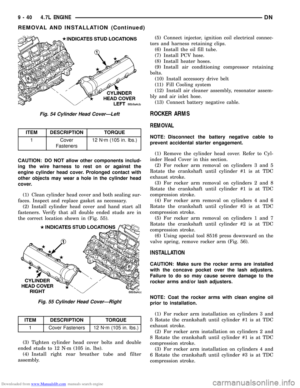
the correct location shown in (Fig. 55).
(3) Tighten cylinder head cover bolts and double
ended studs to 12 N´m (105 in. lbs).
(4) Install right rear breather tube and filter
assembly.(5) Connect injector, ignition coil electrical connec-
tors and harness retaining clips.
(6) Install the oil fill tube.
(7) Install PCV hose.
(8) Install heater hoses.
(9) Install air conditioning compressor retaining
bolts.
(10) Install accessory drive belt
(11) Fill Cooling system
(12) Install air cleaner assembly, resonator assem-
bly and air inlet hose.
(13) Connect battery negative cable.
ROCKER ARMS
REMOVAL
NOTE: Disconnect the battery negative cable to
prevent accidental starter engagement.
(1) Remove the cylinder head cover. Refer to Cyl-
inder Head Cover in this section.
(2) For rocker arm removal on cylinders 3 and 5
Rotate the crankshaft until cylinder #1 is at TDC
exhaust stroke.
(3) For rocker arm removal on cylinders 2 and 8
Rotate the crankshaft until cylinder #1 is at TDC
compression stroke.
(4) For rocker arm removal on cylinders 4 and 6
Rotate the crankshaft until cylinder #3 is at TDC
compression stroke.
(5) For rocker arm removal on cylinders 1 and 7
Rotate the crankshaft until cylinder #2 is at TDC
compression stroke.
(6) Using special tool 8516 press downward on the
valve spring, remove rocker arm (Fig. 56).
INSTALLATION
CAUTION: Make sure the rocker arms are installed
with the concave pocket over the lash adjusters.
Failure to do so may cause severe damage to the
rocker arms and/or lash adjusters.
NOTE: Coat the rocker arms with clean engine oil
prior to installation.
(1) For rocker arm installation on cylinders 3 and
5 Rotate the crankshaft until cylinder #1 is at TDC
exhaust stroke.
(2) For rocker arm installation on cylinders 2 and
8 Rotate the crankshaft until cylinder #1 is at TDC
compression stroke.
(3) For rocker arm installation on cylinders 4 and
6 Rotate the crankshaft until cylinder #3 is at TDC
compression stroke.
Fig. 54 Cylinder Head CoverÐLeft
ITEM DESCRIPTION TORQUE
1 Cover
Fasteners12 N´m (105 in. lbs.)
Fig. 55 Cylinder Head CoverÐRight
ITEM DESCRIPTION TORQUE
1 Cover Fasteners 12 N´m (105 in. lbs.)
9 - 40 4.7L ENGINEDN
REMOVAL AND INSTALLATION (Continued)
Page 70 of 193
Downloaded from www.Manualslib.com manuals search engine ENGINE OIL PRESSURE SENDING UNIT
REMOVAL
(1) Disconnect the negative cable from the battery.
(2) Raise vehicle on hoist.
(3) Remove front splash shield.
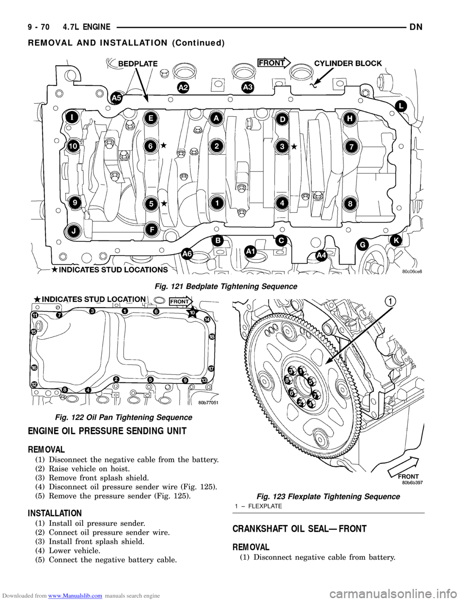
(4) Disconnect oil pressure sender wire (Fig. 125).
(5) Remove the pressure sender (Fig. 125).
INSTALLATION
(1) Install oil pressure sender.
(2) Connect oil pressure sender wire.
(3) Install front splash shield.
(4) Lower vehicle.
(5) Connect the negative battery cable.CRANKSHAFT OIL SEALÐFRONT
REMOVAL
(1) Disconnect negative cable from battery.
Fig. 121 Bedplate Tightening Sequence
Fig. 122 Oil Pan Tightening Sequence
Fig. 123 Flexplate Tightening Sequence
1 ± FLEXPLATE
9 - 70 4.7L ENGINEDN
REMOVAL AND INSTALLATION (Continued)
Page 75 of 193
Downloaded from www.Manualslib.com manuals search engine NOTE: Once the oil pressure relief valve, cup plug,
and pin are removed, the pump assembly must be
replaced.
(3) If it is necessary to remove the pressure relief
valve, drive the roll pin from pump housing and
remove cup plug, spring and valve.
ASSEMBLE
(1) Wash all parts in a suitable solvent and inspect
carefully for damage or wear.
(2) Install inner and outer rotors
(3) Install oil pump cover plate and install cover
bolts and tighten them to 12 N´m (105 in. lbs.).
(4) Prime oil pump before installation by filling
rotor cavity with engine oil.
(5) If oil pressure is low and pump is within spec-
ifications, inspect for worn engine bearings or other
causes for oil pressure loss.
CLEANING AND INSPECTION
INTAKE MANIFOLD
CLEANING
NOTE: There is NO approved repair procedure for
the intake manifold. If severe damage is found dur-
ing inspection, the intake manifold must be
replaced.
Before installing the intake manifold thoroughly
clean the mating surfaces. Use a suitable cleaning
solvent, then air dry.
INSPECTION
(1) Inspect the intake sealing surface for cracks,
nicks and distortion.
(2) Inspect the intake manifold vacuum hose fit-
tings for looseness or blockage.
(3) Inspect the manifold to throttle body mating
surface for cracks, nicks and distortion.
EXHAUST MANIFOLD
CLEANING
(1) Clean the exhaust manifold using a suitable
cleaning solvent, then allow to air dry.
(2) Clean all gasket residue from the manifold
mating surface.
INSPECTION
(1) Inspect the exhaust manifold for cracks in the
mating surface and at every mounting bolt hole.
(2) Using a straight edge and a feeler gauge, check
the mating surface for warp and twist.(3) Inspect the manifold to exhaust pipe mating
surface for cracks, gouges, or other damage that
would prevent sealing.
CYLINDER HEADS
CLEANING
CYLINDER HEAD GASKET SURFACE PREPARATION
To ensure engine gasket sealing, proper surface
preparation must be performed, especially with the
use of aluminum engine components.
Never use the following to clean gasket surfaces:
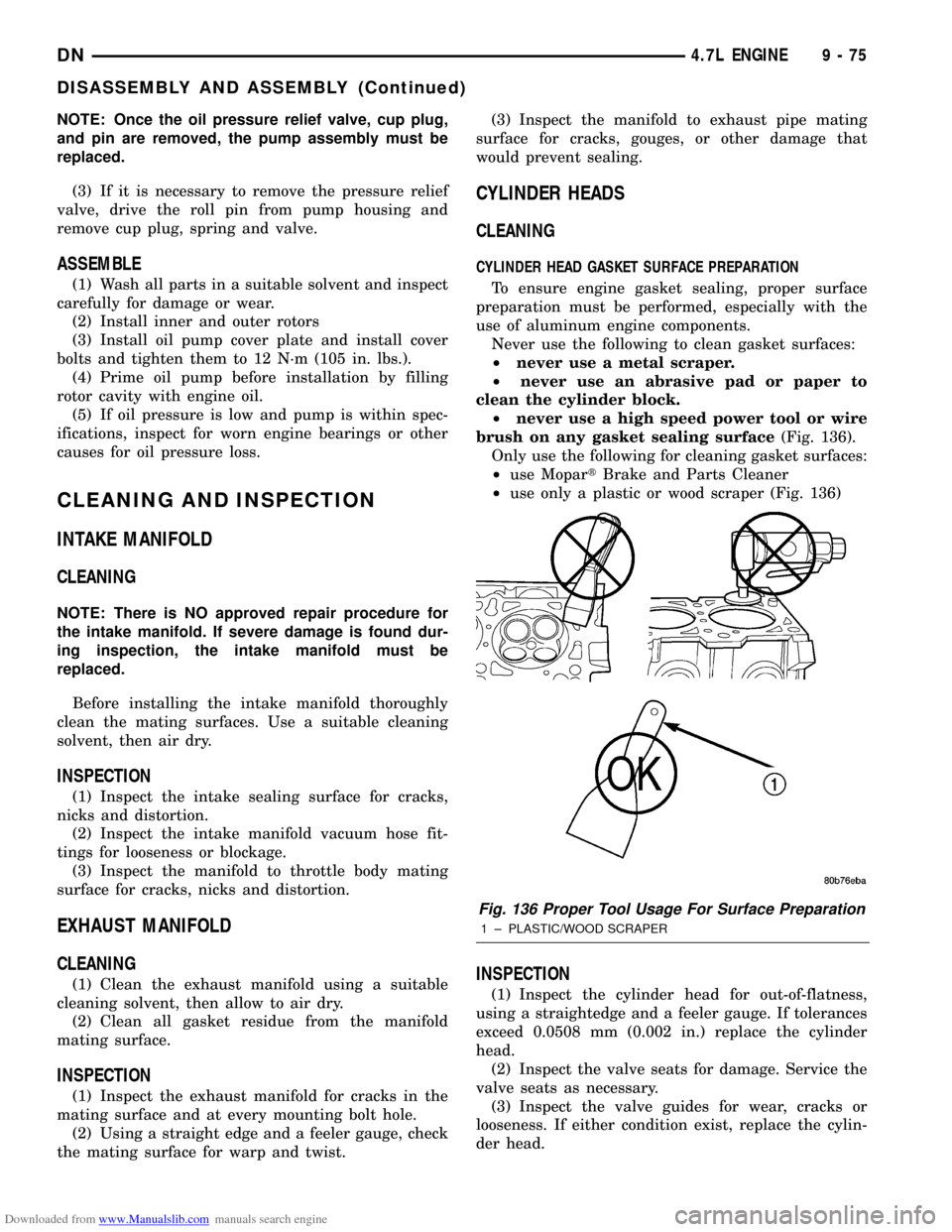
²never use a metal scraper.
²never use an abrasive pad or paper to
clean the cylinder block.
²never use a high speed power tool or wire
brush on any gasket sealing surface(Fig. 136).
Only use the following for cleaning gasket surfaces:
²use MopartBrake and Parts Cleaner
²use only a plastic or wood scraper (Fig. 136)
INSPECTION
(1) Inspect the cylinder head for out-of-flatness,
using a straightedge and a feeler gauge. If tolerances
exceed 0.0508 mm (0.002 in.) replace the cylinder
head.
(2) Inspect the valve seats for damage. Service the
valve seats as necessary.
(3) Inspect the valve guides for wear, cracks or
looseness. If either condition exist, replace the cylin-
der head.
Fig. 136 Proper Tool Usage For Surface Preparation
1 ± PLASTIC/WOOD SCRAPER
DN4.7L ENGINE 9 - 75
DISASSEMBLY AND ASSEMBLY (Continued)
Page 76 of 193
Downloaded from www.Manualslib.com manuals search engine PISTON AND CONNECTING ROD
CLEANING
CAUTION: DO NOT use a wire wheel or other abra-
sive cleaning devise to clean the pistons or con-
necting rods. The pistons have a Moly coating, this
coating must not be damaged.
(1) Using a suitable cleaning solvent clean the pis-
tons in warm water and towel dry.
(2) Use a wood or plastic scraper to clean the ring
land grooves.
CAUTION: DO NOT remove the piston pin from the
piston and connecting rod assembly.
INSPECTION
Check the crankshaft connecting rod journal for
excessive wear, taper and scoring.
Check the pistons for taper and elliptical shape
before they are fitted into the cylinder bore.
Replace any piston and connecting rod not meeting
the specifications.
OIL PAN
CLEANING
(1) Clean oil pan in solvent and wipe dry with a
clean cloth.
(2) Clean the oil pan gasket surface.DO NOTuse
a grinder wheel or other abrasive tool to clean seal-
ing surface.
(3) Clean oil screen and tube thoroughly in clean
solvent.
INSPECTION
(1) Inspect oil drain plug and plug hole for
stripped or damaged threads. Repair as necessary.
(2) Inspect the oil pan mounting flange for bends
or distortion. Straighten flange, if necessary.
OIL PUMP
CLEANING
(1) Wash all parts in a suitable solvent.
INSPECTION
CAUTION: Oil pump pressure relief valve and
spring should not be removed from the oil pump. If
the these components are disassembled andùr
removed from the pump the entire oil pump assem-
bly must be replaced.(1) Clean all parts thoroughly. Mating surface of
the oil pump housing should be smooth. If the pump
cover is scratched or grooved the oil pump assembly
should be replaced.
(2) Lay a straight edge across the pump cover sur-
face (Fig. 137). If a 0.025 mm (0.001 in.) feeler gauge
can be inserted between the cover and the straight
edge the oil pump assembly should be replaced.
(3) Measure the thickness of the outer rotor (Fig.
138). If the outer rotor thickness measures at 12.005
mm (0.400 in.) or less the oil pump assembly must be
replaced.
(4) Measure the diameter of the outer rotor. If the
outer rotor diameter measures at 85.925 mm (0.400
in.) or less the oil pump assembly must be replaced.
(5) Measure the thickness of the inner rotor (Fig.
139). If the inner rotor thickness measures at 12.005
mm (0.400 in.) or less then the oil pump assembly
must be replaced.
(6) Slide outer rotor into the body of the oil pump.
Press the outer rotor to one side of the oil pump body
and measure clearance between the outer rotor and
the body (Fig. 140). If the measurement is 0.47mm
(0.0186 in.) or more the oil pump assembly must be
replaced.
(7) Install the inner rotor in the into the oil pump
body. Measure the clearance between the inner and
outer rotors (Fig. 141). If the clearance between the
rotors is .150 mm (0.006 in.) or more the oil pump
assembly must be replaced.
(8) Place a straight edge across the body of the oil
pump (between the bolt holes), if a feeler gauge of
.095 mm (0.0038 in.) or greater can be inserted
between the straightedge and the rotors, the pump
must be replaced (Fig. 142).
NOTE: 4.7 Oil pump is released as an assembly.
There are no DaimlerChrysler part numbers for Sub-
Assembly components. In the event the oil pump is
not functioning or out of specification it must be
replaced as an assembly.
CYLINDER BLOCK
CLEANING
Thoroughly clean the oil pan and engine block gas-
ket surfaces.
Use compressed air to clean out:
²The galley at the oil filter adaptor hole.
²The front and rear oil galley holes.
²The feed holes for the crankshaft main bearings.
Once the block has been completely cleaned, apply
Loctite PST pipe sealant with Teflon 592 to the
threads of the front and rear oil galley plugs. Tighten
the plugs to 34 N´m (25 ft. lbs.) torque.
9 - 76 4.7L ENGINEDN
CLEANING AND INSPECTION (Continued)
Page 80 of 193
Downloaded from www.Manualslib.com manuals search engine DESCRIPTION SPECIFICATION
Exhaust
Opens (BTDC) 232.5É
Closes (ATDC) 21.2É
Duration 253.70É
Valve Overlap 17.6É
VA LV E S
Face Angle 45É - 45.5É
Head Diameter
Intake 48.52 - 48.78 mm
(1.9103 - 1.9205 in.)
Exhaust 36.87 - 37.13 mm
1.4516 - 1.4618 in.)
Length (Overall)
Intake 113.45 - 114.21 mm
(4.4666 - 4.4965)
Exhaust 114.92 - 115.68 mm
(4.5244 - 4.5543 in.)
Stem Diameter
Intake 6.931 - 6.957 mm
(0.2729 - 0.2739 in.)
Exhaust 6.902 - 6.928 mm
(0.2717 - 0.2728 in.)
Stem - to - Guide
Clearance
Intake .018 -.069 mm
(0.0008 - 0.0028 in.)
Exhaust .047 -.098 mm
(0.0019 - 0.0039 in.)
Max. Allowable Stem -
to -
Guide Clearance
(Rocking Method)
Intake 0.069 mm (0.0028 in.)
Exhaust 0.098 mm (0.0039 in.)
Valve Lift (Zero Lash)
Intake 11.25 mm (0.443 in.)
Exhaust 10.90 mm (0.4292 in.)
VALVE SPRING
Free Lenght (Approx)
Intake and Exhaust 48.6 mm (1.9134 in.)DESCRIPTION SPECIFICATION
Spring Force (Valve
Closed)
Intake and Exhaust 315.5 - 352.5 N @ 40.89
mm
(70.92722 - 79.24515 lbs.
@ 1.6099 in.)
Spring Force (Valve
Open)
Intake and Exhaust 786.0 - 860.0 N @ 29.64
mm
176.6998 - 193.3357 lbs.
@ 1.167 in.)
Number of Coils
Intake and Exhaust 6.69
Wire Diameter
Intake and Exhaust 4.2799 - 4.3561 mm
(0.1685 - 0.1715 in.)
Installed Height
(Top of Valve Stem Seal
to Bottom of Retainer)
Nominal
Early Build
Intake 40.97 mm (1.613 in.)
Exhaust 40.81 mm (1.606 in.)
Late Build
Intake 40.11 mm (1.5792 in.)
Exhaust 40.13 mm (1.58 in.)
CYLINDER HEAD
Gasket Thickness
(Compressed) .7 mm (0.0276 in.)
Valve Seat Angle 44.5É - 45.0É
Valve Seat Runout (MAX) 0.051 mm (0.002 in.)
Valve Seat Width
Intake 1.75 - 2.36 mm
(0.0698 - 0.0928 in.)
Exhaust 1.71 - 2.32 mm
(0.0673 - 0.0911 in.)
Guide Bore Diameter (Std.)6.975 - 7.00 mm
(0.2747 - 0.2756 in.)
Cylinder Head Warpage
(Flatness) 0.0508 mm (0.002 in.)
9 - 80 4.7L ENGINEDN
SPECIFICATIONS (Continued)
2000 DN Service Manual
Publication No. 81-370-0016
TSB 26-12-99 December, 1999
Page 92 of 193
Downloaded from www.Manualslib.com manuals search engine Scrape or wire brush all gasket surfaces to remove
all loose material. Inspect stamped parts to ensure
gasket rails are flat. Flatten rails with a hammer on
a flat plate, if required. Gasket surfaces must be free
of oil and dirt. Make sure the old gasket material is
removed from blind attaching holes.
GASKET APPLICATION
Assembling parts using a form-in-place gasket
requires care.
Mopar Silicone Rubber Adhesive Sealant should be
applied in a continuous bead approximately 3 mm
(0.12 inch) in diameter. All mounting holes must be
circled. For corner sealing,a3or6mm(1/8 or 1/4
inch) drop is placed in the center of the gasket con-
tact area. Uncured sealant may be removed with a
shop towel. Components should be torqued in place
while the sealant is still wet to the touch (within 10
minutes). The use of a locating dowel is recom-
mended during assembly to prevent smearing the
material off location.
Mopar Gasket Maker should be applied sparingly
to one gasket surface. The sealant diameter should
be 1.00 mm (0.04 inch) or less. Be certain the mate-
rial surrounds each mounting hole. Excess material
can easily be wiped off. Components should be
torqued in place within 15 minutes. The use of a
locating dowel is recommended during assembly to
prevent smearing the material off location.
ENGINE PERFORMANCE
It is important that the vehicle is operating to its
optimum performance level to maintain fuel economy
and the lowest emission levels. If vehicle is not oper-
ating to these standards, refer to Engine Diagnosis
outlined in this section. The following procedures can
assist in achieving the proper engine diagnosis.
(1) Test cranking amperage draw. Refer to Electri-
cal Group 8B, Cold Cranking Test.
(2) Check intake manifold bolt torque.
(3) Perform cylinder compression test. Refer to
Cylinder Compression Pressure Test in the Engine
Diagnosis area of this section.
(4) Clean or replace spark plugs as necessary and
adjust gap as specified in Electrical Group 8D.
Tighten to specifications.
(5) Test resistance of spark plug cables. Refer to
Electrical Group 8D, Spark Plug Cables.
(6) Inspect the primary wires. Test coil output volt-
age and primary resistance. Replace parts as neces-
sary. Refer to Electrical Group 8D, for specifications.
(7) Test fuel pump for pressure. Refer to Group 14,
Fuel System Specifications.
(8) The air filter elements should be replaced as
specified in Lubrication and Maintenance, Group 0.(9) Inspect crankcase ventilation system as out
lined in Group 0, Lubrication and Maintenance. For
emission controls see Group 25, Emission Controls
for service procedures.
(10) Road test vehicle as a final test.
ENGINE OIL
WARNING: NEW OR USED ENGINE OIL CAN BE
IRRITATING TO THE SKIN. AVOID PROLONGED OR
REPEATED SKIN CONTACT WITH ENGINE OIL.
CONTAMINANTS IN USED ENGINE OIL, CAUSED BY
INTERNAL COMBUSTION, CAN BE HAZARDOUS TO
YOUR HEALTH. THOROUGHLY WASH EXPOSED
SKIN WITH SOAP AND WATER. DO NOT WASH
SKIN WITH GASOLINE, DIESEL FUEL, THINNER, OR
SOLVENTS, HEALTH PROBLEMS CAN RESULT. DO
NOT POLLUTE, DISPOSE OF USED ENGINE OIL
PROPERLY.
ENGINE OIL SPECIFICATION
CAUTION: Do not use non-detergent or straight
mineral oil when adding or changing crankcase
lubricant. Engine failure can result.
API SERVICE GRADE CERTIFIED
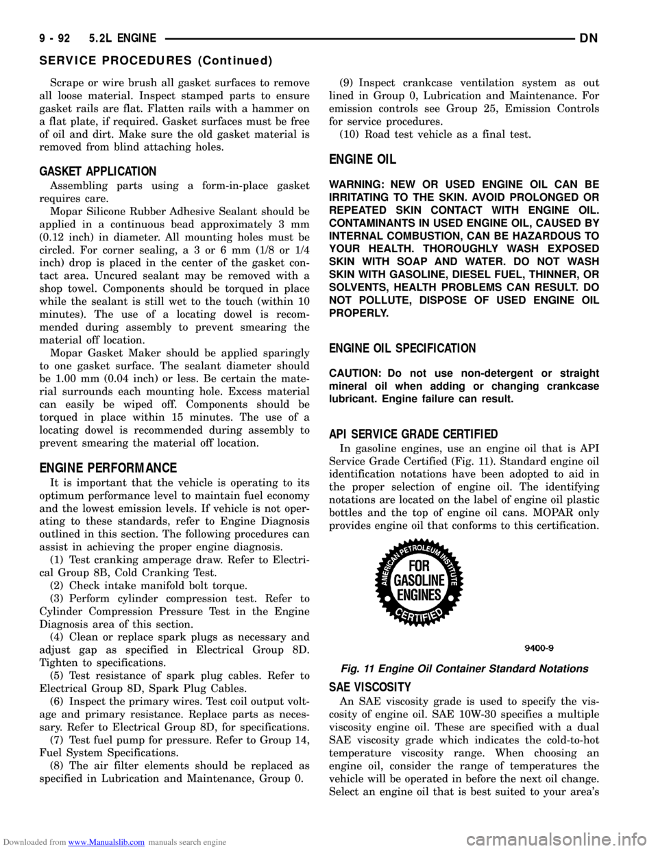
In gasoline engines, use an engine oil that is API
Service Grade Certified (Fig. 11). Standard engine oil
identification notations have been adopted to aid in
the proper selection of engine oil. The identifying
notations are located on the label of engine oil plastic
bottles and the top of engine oil cans. MOPAR only
provides engine oil that conforms to this certification.
SAE VISCOSITY
An SAE viscosity grade is used to specify the vis-
cosity of engine oil. SAE 10W-30 specifies a multiple
viscosity engine oil. These are specified with a dual
SAE viscosity grade which indicates the cold-to-hot
temperature viscosity range. When choosing an
engine oil, consider the range of temperatures the
vehicle will be operated in before the next oil change.
Select an engine oil that is best suited to your area's
Fig. 11 Engine Oil Container Standard Notations
9 - 92 5.2L ENGINEDN
SERVICE PROCEDURES (Continued)
Page 101 of 193
Downloaded from www.Manualslib.com manuals search engine (1) Disconnect the negative cable from the battery.
(2) Raise vehicle on hoist.
(3) Install engine lifting (support) fixture.
(4) Remove front axle assembly. (Refer to Group 3,
Differential and Driveline in this publication.)
(5)Left mount insulator only.Remove starter
wires and starter motor assembly.
(6) Remove insulator to frame through bolt (Fig.
33).
(7) Raise engine slightly.
(8) Remove upper insulator to support bracket
stud nut and insulator to support through bolt.
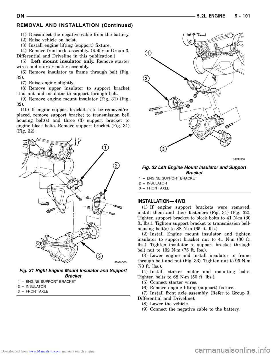
(9) Remove engine mount insulator (Fig. 31) (Fig.
32).
(10) If engine support bracket is to be removed/re-
placed, remove support bracket to transmission bell
housing bolt(s) and three (3) support bracket to
engine block bolts. Remove support bracket (Fig. 31)
(Fig. 32).
INSTALLATIONÐ4WD
(1) If engine support brackets were removed,
install them and their fasteners (Fig. 31) (Fig. 32).
Tighten support bracket to block bolts to 41 N´m (30
ft. lbs.). Tighten support bracket to transmission bell-
housing bolt(s) to 88 N´m (65 ft. lbs.).
(2) Install Engine mount insulator and tighten
insulator to support bracket nut to 41 N´m (30 ft.
lbs.). Tighten insulator to support bracket through
bolt nut to 102 N´m (75 ft. lbs.).
(3) Lower engine and install insulator to frame
through bolt and nut (Fig. 33). Tighten nut to 95 N´m
(70 ft. lbs.).
(4) Install starter motor and mounting bolts.
Tighten bolts to 68 N´m (50 ft. lbs.).
(5) Connect starter wires.
(6) Remove engine lifting (support) fixture.
(7) Install front axle assembly. (Refer to Group 3,
Differential and Driveline).
(8) Lower the vehicle.
(9) Connect the negative cable to the battery.
Fig. 31 Right Engine Mount Insulator and Support
Bracket
1 ± ENGINE SUPPORT BRACKET
2 ± INSULATOR
3 ± FRONT AXLE
Fig. 32 Left Engine Mount Insulator and Support
Bracket
1 ± ENGINE SUPPORT BRACKET
2 ± INSULATOR
3 ± FRONT AXLE
DN5.2L ENGINE 9 - 101
REMOVAL AND INSTALLATION (Continued)