service indicator DODGE DURANGO 2000 1.G User Guide
[x] Cancel search | Manufacturer: DODGE, Model Year: 2000, Model line: DURANGO, Model: DODGE DURANGO 2000 1.GPages: 193, PDF Size: 5.65 MB
Page 151 of 193

Downloaded from www.Manualslib.com manuals search engine (2) Check intake manifold bolt torque.
(3) Perform cylinder compression test. Refer to
Cylinder Compression Pressure Test in the Engine
Diagnosis area of this section.
(4) Clean or replace spark plugs as necessary and
adjust gap as specified in Electrical Group 8D.
Tighten to specifications.
(5) Test resistance of spark plug cables. Refer to
Electrical Group 8D, Spark Plug Cables.
(6) Inspect the primary wires. Test coil output volt-
age and primary resistance. Replace parts as neces-
sary. Refer to Electrical Group 8D, for specifications.
(7) Test fuel pump for pressure. Refer to Group 14,
Fuel System Specifications.
(8) The air filter elements should be replaced as
specified in Lubrication and Maintenance, Group 0.
(9) Inspect crankcase ventilation system as out
lined in Group 0, Lubrication and Maintenance. For
emission controls see Group 25, Emission Controls
for service procedures.
(10) Road test vehicle as a final test.
ENGINE OIL
WARNING: NEW OR USED ENGINE OIL CAN BE
IRRITATING TO THE SKIN. AVOID PROLONGED OR
REPEATED SKIN CONTACT WITH ENGINE OIL.
CONTAMINANTS IN USED ENGINE OIL, CAUSED BY
INTERNAL COMBUSTION, CAN BE HAZARDOUS TO
YOUR HEALTH. THOROUGHLY WASH EXPOSED
SKIN WITH SOAP AND WATER. DO NOT WASH
SKIN WITH GASOLINE, DIESEL FUEL, THINNER, OR
SOLVENTS, HEALTH PROBLEMS CAN RESULT. DO
NOT POLLUTE, DISPOSE OF USED ENGINE OIL
PROPERLY.
ENGINE OIL SPECIFICATION
CAUTION: Do not use non-detergent or straight
mineral oil when adding or changing crankcase
lubricant. Engine failure can result.
API SERVICE GRADE CERTIFIED
In gasoline engines, use an engine oil that is API
Service Grade Certified (Fig. 12). Standard engine oil
identification notations have been adopted to aid in
the proper selection of engine oil. The identifying
notations are located on the label of engine oil plastic
bottles and the top of engine oil cans. MOPAR only
provides engine oil that conforms to this certification.
SAE VISCOSITY
An SAE viscosity grade is used to specify the vis-
cosity of engine oil. SAE 10W-30 specifies a multiple
viscosity engine oil. These are specified with a dualSAE viscosity grade which indicates the cold-to-hot
temperature viscosity range. When choosing an
engine oil, consider the range of temperatures the
vehicle will be operated in before the next oil change.
Select an engine oil that is best suited to your area's
particular ambient temperature range and variation
(Fig. 13).
ENERGY CONSERVING OIL
An Energy Conserving type oil is recommended for
gasoline engines. The designation of ENERGY CON-
SERVING is located on the label of an engine oil con-
tainer.
OIL LEVEL INDICATOR (DIPSTICK)
The engine oil level indicator is located at the right
front of the engine, left of the generator on 5.9L
engines (Fig. 14).
CRANKCASE OIL LEVEL INSPECTION
CAUTION: Do not overfill crankcase with engine oil,
oil foaming and oil pressure loss can result.
To ensure proper lubrication of an engine, the
engine oil must be maintained at an acceptable level.
The acceptable levels are indicated between the ADD
and SAFE marks on the engine oil dipstick.
(1) Position vehicle on level surface.
Fig. 12 Engine Oil Container Standard Notations
Fig. 13 Temperature/Engine Oil Viscosity
Recommendation
9 - 150 5.9L ENGINEDN
SERVICE PROCEDURES (Continued)
Page 154 of 193

Downloaded from www.Manualslib.com manuals search engine (6) Identify the fluid in the cylinders (i.e. coolant,
fuel, oil, etc.).
(7) Make sure all fluid has been removed from the
cylinders.
(8) Repair engine or components as necessary to
prevent this problem from occurring again.
(9) Squirt engine oil into the cylinders to lubricate
the walls. This will prevent damage on restart.
(10) Install new spark plugs.
(11) Drain engine oil. Remove and discard the oil
filter.
(12) Install the drain plug. Tighten the plug to 34
N´m (25 ft. lbs.) torque.
(13) Install a new oil filter.
(14) Fill engine crankcase with the specified
amount and grade of oil.
(15) Connect the negative cable to the battery.
(16) Start the engine and check for any leaks.
VALVE TIMING
(1) Turn crankshaft until the No.6 exhaust valve is
closing and No.6 intake valve is opening.
(2) Insert a 6.350 mm (1/4 inch) spacer between
rocker arm pad and stem tip of No.1 intake valve.
Allow spring load to bleed tappet down giving in
effect a solid tappet.
(3) Install a dial indicator so plunger contacts
valve spring retainer as nearly perpendicular as pos-
sible. Zero the indicator.
(4) Rotate the crankshaft clockwise (normal run-
ning direction) until the valve has lifted 0.863 mm
(0.034 inch). The timing of the crankshaft should
now read from 10É before top dead center to 2É after
top dead center. Remove spacer.
CAUTION: DO NOT turn crankshaft any further
clockwise as valve spring might bottom and result
in serious damage.
If reading is not within specified limits:
²Check sprocket index marks.
²Inspect timing chain for wear.
²Check accuracy of DC mark on timing indicator.
VALVE SERVICE
VALVE CLEANING
Clean valves thoroughly. Discard burned, warped
and cracked valves.
Remove carbon and varnish deposits from inside of
valve guides with a reliable guide cleaner.
VALVE INSPECTION
Measure valve stems for wear. If wear exceeds
0.051 mm (0.002 inch), replace the valve.
VALVE GUIDES
Measure valve stem guide clearance as follows:
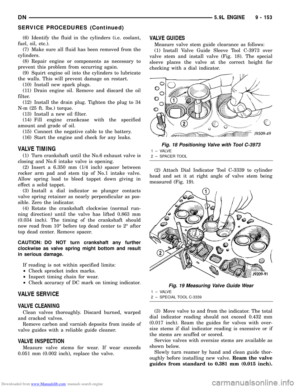
(1) Install Valve Guide Sleeve Tool C-3973 over
valve stem and install valve (Fig. 18). The special
sleeve places the valve at the correct height for
checking with a dial indicator.
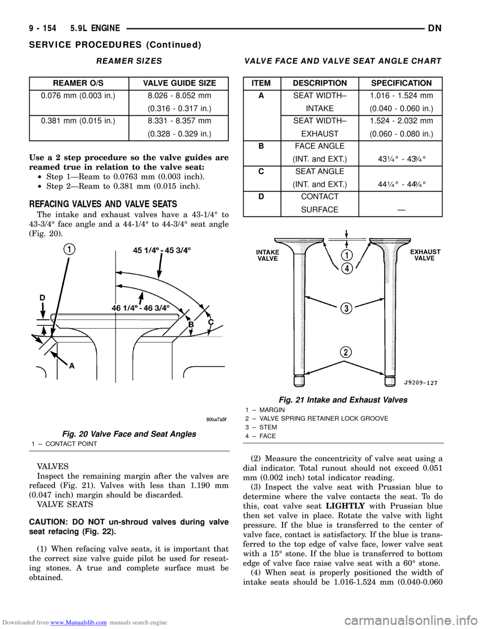
(2) Attach Dial Indicator Tool C-3339 to cylinder
head and set it at right angle of valve stem being
measured (Fig. 19).
(3) Move valve to and from the indicator. The total
dial indicator reading should not exceed 0.432 mm
(0.017 inch). Ream the guides for valves with over-
size stems if dial indicator reading is excessive or if
the stems are scuffed or scored.
Service valves with oversize stems are available as
shown below.
Slowly turn reamer by hand and clean guide thor-
oughly before installing new valve.Ream the valve
guides from standard to 0.381 mm (0.015 inch).
Fig. 18 Positioning Valve with Tool C-3973
1 ± VALVE
2 ± SPACER TOOL
Fig. 19 Measuring Valve Guide Wear
1 ± VALVE
2 ± SPECIAL TOOL C-3339
DN5.9L ENGINE 9 - 153
SERVICE PROCEDURES (Continued)
Page 155 of 193

Downloaded from www.Manualslib.com manuals search engine Use a 2 step procedure so the valve guides are
reamed true in relation to the valve seat:
²Step 1ÐReam to 0.0763 mm (0.003 inch).
²Step 2ÐReam to 0.381 mm (0.015 inch).
REFACING VALVES AND VALVE SEATS
The intake and exhaust valves have a 43-1/4É to
43-3/4É face angle and a 44-1/4É to 44-3/4É seat angle
(Fig. 20).
VALVES
Inspect the remaining margin after the valves are
refaced (Fig. 21). Valves with less than 1.190 mm
(0.047 inch) margin should be discarded.
VALVE SEATS
CAUTION: DO NOT un-shroud valves during valve
seat refacing (Fig. 22).
(1) When refacing valve seats, it is important that
the correct size valve guide pilot be used for reseat-
ing stones. A true and complete surface must be
obtained.(2) Measure the concentricity of valve seat using a
dial indicator. Total runout should not exceed 0.051
mm (0.002 inch) total indicator reading.
(3) Inspect the valve seat with Prussian blue to
determine where the valve contacts the seat. To do
this, coat valve seatLIGHTLYwith Prussian blue
then set valve in place. Rotate the valve with light
pressure. If the blue is transferred to the center of
valve face, contact is satisfactory. If the blue is trans-
ferred to the top edge of valve face, lower valve seat
with a 15É stone. If the blue is transferred to bottom
edge of valve face raise valve seat with a 60É stone.
(4) When seat is properly positioned the width of
intake seats should be 1.016-1.524 mm (0.040-0.060
REAMER SIZES
REAMER O/S VALVE GUIDE SIZE
0.076 mm (0.003 in.) 8.026 - 8.052 mm
(0.316 - 0.317 in.)
0.381 mm (0.015 in.) 8.331 - 8.357 mm
(0.328 - 0.329 in.)
Fig. 20 Valve Face and Seat Angles
1 ± CONTACT POINT
VALVE FACE AND VALVE SEAT ANGLE CHART
ITEM DESCRIPTION SPECIFICATION
ASEAT WIDTH± 1.016 - 1.524 mm
INTAKE (0.040 - 0.060 in.)
SEAT WIDTH± 1.524 - 2.032 mm
EXHAUST (0.060 - 0.080 in.)
BFACE ANGLE
(INT. and EXT.) 43
1¤4É-433¤4É
CSEAT ANGLE
(INT. and EXT.) 44
1¤4É-443¤4É
DCONTACT
SURFACE Ð
Fig. 21 Intake and Exhaust Valves
1 ± MARGIN
2 ± VALVE SPRING RETAINER LOCK GROOVE
3 ± STEM
4±FACE
9 - 154 5.9L ENGINEDN
SERVICE PROCEDURES (Continued)
Page 186 of 193

Downloaded from www.Manualslib.com manuals search engine CYLINDER BLOCK
CLEANING
Clean cylinder block thoroughly and check all core
hole plugs for evidence of leaking.
INSPECTION
Examine block for cracks or fractures.
The cylinder walls should be checked for out-of-
round and taper with Cylinder Bore Indicator Tool
C-119. The cylinder block should be bored and honed
with new pistons and rings fitted if:
²The cylinder bores show more than 0.127 mm
(0.005 inch) out-of-round.
²The cylinder bores show a taper of more than
0.254 mm (0.010 inch).
²The cylinder walls are badly scuffed or scored.
Boring and honing operation should be closely coor-
dinated with the fitting of pistons and rings so spec-
ified clearances may be maintained.
Refer to Standard Service Procedures in the begin-
ning of this Group for the proper honing of cylinder
bores.
INTAKE MANIFOLD
CLEANING
Clean manifold in solvent and blow dry with com-
pressed air.
Clean cylinder block front and rear gasket surfaces
using a suitable solvent.
The plenum pan rail must be clean and dry (free of
all foreign material).
INSPECTION
Inspect manifold for cracks.
Inspect mating surfaces of manifold for flatness
with a straightedge.
EXHAUST MANIFOLD
CLEANING
Clean mating surfaces on cylinder head and mani-
fold, wash with solvent and blow dry with com-
pressed air.
INSPECTION
Inspect manifold for cracks, Inspect mating sur-
faces of manifold for flatness with a straight edge.
Seal surfaces must be flat within 0.1 mm (0.004 inch)
overall.
SPECIFICATIONS
5.9L ENGINE SPECIFICATIONS
DESCRIPTION SPECIFICATION
Engine Type 90É V-8 OHV
Bore and Stroke 101.6 x 90.9 mm
(4.00 x 3.58 in.)
Displacement 5.9L (360 c.i.)
Compression Ratio 9.1:1
Firing Order 1±8±4±3±6±5±7±2
Lubrication Pressure Feed ±
Full Flow Filtration
Cooling System Liquid Cooled ±
Forced Circulation
Cylinder Block Cast Iron
Cylinder Head Cast Iron
Crankshaft Nodular Iron
Camshaft Nodular Cast Iron
Combustion Chambers Wedge -
High Swirl Valve
Shrouding
Pistons Aluminum Alloy w/strut
Connecting Rods Forged Steel
Cylinder Compression 689.5 kPa
Pressure (Min.) (100 psi)
DESCRIPTION SPECIFICATION
CAMSHAFT
Bearing Diameter
No. 1 50.800 ± 50.825 mm
(2.000 ± 2.001 in.)
No. 2 50.394 ± 50.419 mm
(1.984 ± 1.985 in.)
No. 3 50.013 ± 50.038 mm
(1.969 ± 1.970 in.)
No. 4 49.606 ± 49.632 mm
(1.953 ± 1.954 in.)
No. 5 39.688 ± 39.713 mm
(1.5625 ± 1.5635 in.)
DN5.9L ENGINE 9 - 185
CLEANING AND INSPECTION (Continued)