Part number DODGE DURANGO 2000 1.G Workshop Manual
[x] Cancel search | Manufacturer: DODGE, Model Year: 2000, Model line: DURANGO, Model: DODGE DURANGO 2000 1.GPages: 193, PDF Size: 5.65 MB
Page 18 of 193
Downloaded from www.Manualslib.com manuals search engine Damaged or worn threads can be repaired. Essen-
tially, this repair consists of:
²Drilling out worn or damaged threads.
²Tapping the hole with a special Heli-Coil Tap, or
equivalent.
²Installing an insert into the tapped hole to bring
the hole back to its original thread size.
CYLINDER BOREÐHONING
Before honing, stuff plenty of clean shop towels
under the bores and over the crankshaft to keep
abrasive materials from entering the crankshaft
area.
(1) Used carefully, the Cylinder Bore Sizing Hone
C-823, equipped with 220 grit stones, is the best tool
for this job. In addition to deglazing, it will reduce
taper and out-of-round, as well as removing light
scuffing, scoring and scratches. Usually, a few strokes
will clean up a bore and maintain the required lim-
its.
CAUTION: DO NOT use rigid type hones to remove
cylinder wall glaze.
(2) Deglazing of the cylinder walls may be done if
the cylinder bore is straight and round. Use a cylin-
der surfacing hone, Honing Tool C-3501, equipped
with 280 grit stones (C-3501-3810). about 20-60
strokes, depending on the bore condition, will be suf-
ficient to provide a satisfactory surface. Using honing
oil C-3501-3880, or a light honing oil, available from
major oil distributors.
CAUTION: DO NOT use engine or transmission oil,
mineral spirits, or kerosene.
(3) Honing should be done by moving the hone up
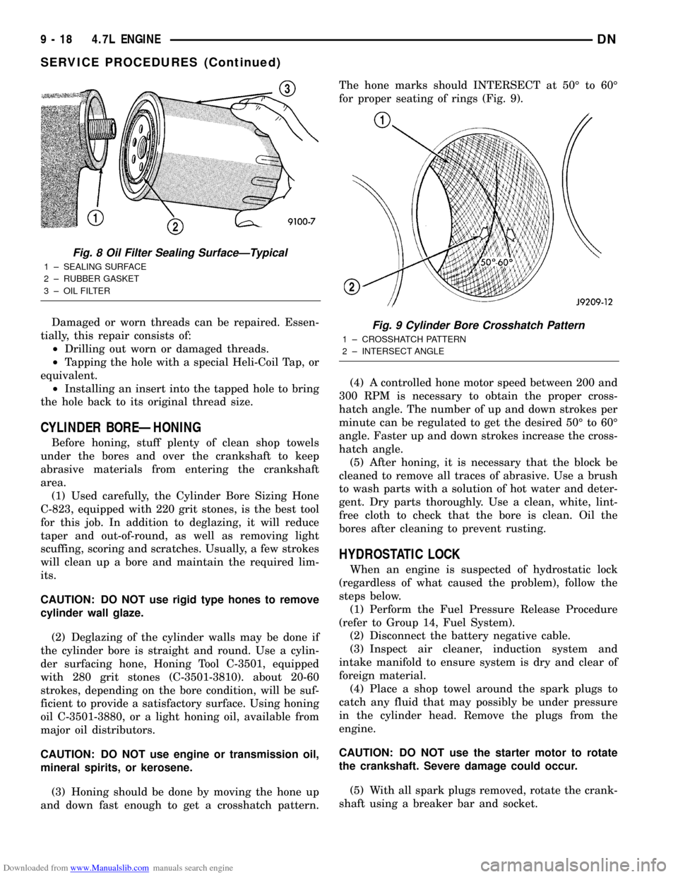
and down fast enough to get a crosshatch pattern.The hone marks should INTERSECT at 50É to 60É
for proper seating of rings (Fig. 9).
(4) A controlled hone motor speed between 200 and
300 RPM is necessary to obtain the proper cross-
hatch angle. The number of up and down strokes per
minute can be regulated to get the desired 50É to 60É
angle. Faster up and down strokes increase the cross-
hatch angle.
(5) After honing, it is necessary that the block be
cleaned to remove all traces of abrasive. Use a brush
to wash parts with a solution of hot water and deter-
gent. Dry parts thoroughly. Use a clean, white, lint-
free cloth to check that the bore is clean. Oil the
bores after cleaning to prevent rusting.
HYDROSTATIC LOCK
When an engine is suspected of hydrostatic lock
(regardless of what caused the problem), follow the
steps below.
(1) Perform the Fuel Pressure Release Procedure
(refer to Group 14, Fuel System).
(2) Disconnect the battery negative cable.
(3) Inspect air cleaner, induction system and
intake manifold to ensure system is dry and clear of
foreign material.
(4) Place a shop towel around the spark plugs to
catch any fluid that may possibly be under pressure
in the cylinder head. Remove the plugs from the
engine.
CAUTION: DO NOT use the starter motor to rotate
the crankshaft. Severe damage could occur.
(5) With all spark plugs removed, rotate the crank-
shaft using a breaker bar and socket.
Fig. 8 Oil Filter Sealing SurfaceÐTypical
1 ± SEALING SURFACE
2 ± RUBBER GASKET
3 ± OIL FILTER
Fig. 9 Cylinder Bore Crosshatch Pattern
1 ± CROSSHATCH PATTERN
2 ± INTERSECT ANGLE
9 - 18 4.7L ENGINEDN
SERVICE PROCEDURES (Continued)
Page 76 of 193
Downloaded from www.Manualslib.com manuals search engine PISTON AND CONNECTING ROD
CLEANING
CAUTION: DO NOT use a wire wheel or other abra-
sive cleaning devise to clean the pistons or con-
necting rods. The pistons have a Moly coating, this
coating must not be damaged.
(1) Using a suitable cleaning solvent clean the pis-
tons in warm water and towel dry.
(2) Use a wood or plastic scraper to clean the ring
land grooves.
CAUTION: DO NOT remove the piston pin from the
piston and connecting rod assembly.
INSPECTION
Check the crankshaft connecting rod journal for
excessive wear, taper and scoring.
Check the pistons for taper and elliptical shape
before they are fitted into the cylinder bore.
Replace any piston and connecting rod not meeting
the specifications.
OIL PAN
CLEANING
(1) Clean oil pan in solvent and wipe dry with a
clean cloth.
(2) Clean the oil pan gasket surface.DO NOTuse
a grinder wheel or other abrasive tool to clean seal-
ing surface.
(3) Clean oil screen and tube thoroughly in clean
solvent.
INSPECTION
(1) Inspect oil drain plug and plug hole for
stripped or damaged threads. Repair as necessary.
(2) Inspect the oil pan mounting flange for bends
or distortion. Straighten flange, if necessary.
OIL PUMP
CLEANING
(1) Wash all parts in a suitable solvent.
INSPECTION
CAUTION: Oil pump pressure relief valve and
spring should not be removed from the oil pump. If
the these components are disassembled andùr
removed from the pump the entire oil pump assem-
bly must be replaced.(1) Clean all parts thoroughly. Mating surface of
the oil pump housing should be smooth. If the pump
cover is scratched or grooved the oil pump assembly
should be replaced.
(2) Lay a straight edge across the pump cover sur-
face (Fig. 137). If a 0.025 mm (0.001 in.) feeler gauge
can be inserted between the cover and the straight
edge the oil pump assembly should be replaced.
(3) Measure the thickness of the outer rotor (Fig.
138). If the outer rotor thickness measures at 12.005
mm (0.400 in.) or less the oil pump assembly must be
replaced.
(4) Measure the diameter of the outer rotor. If the
outer rotor diameter measures at 85.925 mm (0.400
in.) or less the oil pump assembly must be replaced.
(5) Measure the thickness of the inner rotor (Fig.
139). If the inner rotor thickness measures at 12.005
mm (0.400 in.) or less then the oil pump assembly
must be replaced.
(6) Slide outer rotor into the body of the oil pump.
Press the outer rotor to one side of the oil pump body
and measure clearance between the outer rotor and
the body (Fig. 140). If the measurement is 0.47mm
(0.0186 in.) or more the oil pump assembly must be
replaced.
(7) Install the inner rotor in the into the oil pump
body. Measure the clearance between the inner and
outer rotors (Fig. 141). If the clearance between the
rotors is .150 mm (0.006 in.) or more the oil pump
assembly must be replaced.
(8) Place a straight edge across the body of the oil
pump (between the bolt holes), if a feeler gauge of
.095 mm (0.0038 in.) or greater can be inserted
between the straightedge and the rotors, the pump
must be replaced (Fig. 142).
NOTE: 4.7 Oil pump is released as an assembly.
There are no DaimlerChrysler part numbers for Sub-
Assembly components. In the event the oil pump is
not functioning or out of specification it must be
replaced as an assembly.
CYLINDER BLOCK
CLEANING
Thoroughly clean the oil pan and engine block gas-
ket surfaces.
Use compressed air to clean out:
²The galley at the oil filter adaptor hole.
²The front and rear oil galley holes.
²The feed holes for the crankshaft main bearings.
Once the block has been completely cleaned, apply
Loctite PST pipe sealant with Teflon 592 to the
threads of the front and rear oil galley plugs. Tighten
the plugs to 34 N´m (25 ft. lbs.) torque.
9 - 76 4.7L ENGINEDN
CLEANING AND INSPECTION (Continued)
Page 86 of 193
Downloaded from www.Manualslib.com manuals search engine 5.2L ENGINE
TABLE OF CONTENTS
page page
DESCRIPTION AND OPERATION
ENGINE................................86
ENGINE LUBRICATION SYSTEM.............87
EXHAUST MANIFOLD.....................89
INTAKE MANIFOLD.......................89
CYLINDER HEAD COVER GASKET...........90
CYLINDER HEAD.........................90
VALVES AND VALVE SPRINGS..............90
ENGINE OIL PAN.........................90
CRANKSHAFT OIL SEALS..................90
PISTON AND CONNECTING ROD............90
CRANKSHAFT MAIN BEARINGS.............91
CRANKSHAFT...........................91
SERVICE PROCEDURES
FORM-IN-PLACE GASKETS.................91
ENGINE PERFORMANCE..................92
ENGINE OIL.............................92
REPAIR DAMAGED OR WORN THREADS......94
CYLINDER BOREÐHONING................94
HYDROSTATIC LOCK.....................95
VALVE TIMING...........................95
VALVE SERVICE.........................95
MEASURING TIMING CHAIN STRETCH........97
PISTONSÐFITTING.......................98
PISTON RINGSÐFITTING..................98
CONNECTING ROD BEARINGSÐFITTING.....100
CRANKSHAFT MAIN BEARINGSÐFITTING....100
REMOVAL AND INSTALLATION
ENGINE MOUNTSÐFRONT................100
ENGINE MOUNTÐREAR..................102
ENGINE ASSEMBLY......................102
INTAKE MANIFOLD......................103
EXHAUST MANIFOLD....................105
CYLINDER HEAD COVER.................106
ROCKER ARMS AND PUSH RODS..........107
VALVE SPRING AND STEM SEAL
REPLACEMENT-IN VEHICLE.............107CYLINDER HEAD........................107
VALVES AND VALVE SPRINGS.............108
HYDRAULIC TAPPETS....................109
VIBRATION DAMPER.....................109
TIMING CHAIN COVER...................110
TIMING CHAIN..........................111
CAMSHAFT............................111
CAMSHAFT BEARINGS...................113
CRANKSHAFT MAIN BEARINGS............113
DISTRIBUTOR DRIVE SHAFT BUSHING......114
OILPAN...............................115
PISTON AND CONNECTING ROD ASSEMBLY . . 116
CRANKSHAFT..........................116
OIL PUMP.............................117
CRANKSHAFT OIL SEALÐFRONT...........117
CRANKSHAFT OIL SEALSÐREAR...........118
ENGINE CORE OIL AND CAMSHAFT PLUGS . . 120
DISASSEMBLY AND ASSEMBLY
VALVE SERVICE........................121
OIL PUMP.............................123
CYLINDER BLOCK.......................124
CLEANING AND INSPECTION
CYLINDER HEAD COVER.................124
CYLINDER HEAD ASSEMBLY..............124
PISTON AND CONNECTING ROD ASSEMBLY . . 124
OILPAN...............................124
OIL PUMP.............................125
CYLINDER BLOCK.......................127
INTAKE MANIFOLD......................127
EXHAUST MANIFOLD....................127
SPECIFICATIONS
5.2L ENGINE SPECIFICATIONS.............128
TORQUE SPECIFICATIONS................132
SPECIAL TOOLS
5.2L ENGINE...........................132
DESCRIPTION AND OPERATION
ENGINE
DESCRIPTION
The 5.2 Liter (318 CID) eight-cylinder engine is a
V-Type lightweight, single cam, overhead valve
engine with hydraulic roller tappets.
The engine lubrication system consists of a rotor
type oil pump and a full flow oil filter.The cylinders are numbered from front to rear; 1,
3, 5, 7 on the left bank and 2, 4, 6, 8 on the right
bank. The firing order is 1-8-4-3-6-5-7-2 (Fig. 1). This
engine is designed for unleaded fuel.
The engine serial number is stamped into a
machined pad located on the left, front corner of the
cylinder block. When component part replacement is
necessary, use the engine type and serial number for
reference (Fig. 2).
9 - 86 5.2L ENGINEDN
Page 90 of 193
Downloaded from www.Manualslib.com manuals search engine CYLINDER HEAD COVER GASKET
DESCRIPTION
The cylinder head cover gasket is a steel-backed
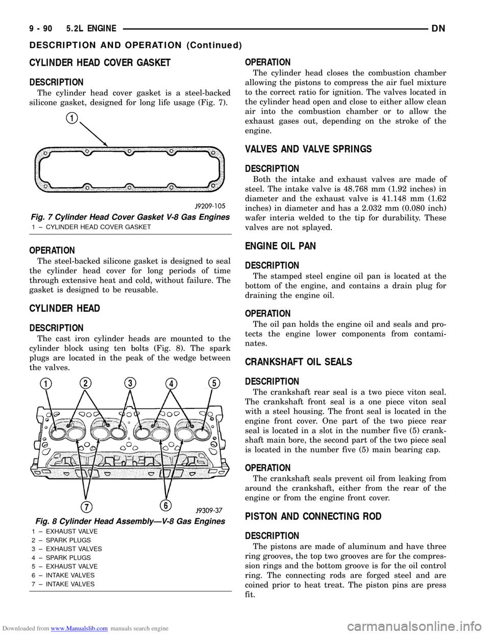
silicone gasket, designed for long life usage (Fig. 7).
OPERATION
The steel-backed silicone gasket is designed to seal
the cylinder head cover for long periods of time
through extensive heat and cold, without failure. The
gasket is designed to be reusable.
CYLINDER HEAD
DESCRIPTION
The cast iron cylinder heads are mounted to the
cylinder block using ten bolts (Fig. 8). The spark
plugs are located in the peak of the wedge between
the valves.
OPERATION
The cylinder head closes the combustion chamber
allowing the pistons to compress the air fuel mixture
to the correct ratio for ignition. The valves located in
the cylinder head open and close to either allow clean
air into the combustion chamber or to allow the
exhaust gases out, depending on the stroke of the
engine.
VALVES AND VALVE SPRINGS
DESCRIPTION
Both the intake and exhaust valves are made of
steel. The intake valve is 48.768 mm (1.92 inches) in
diameter and the exhaust valve is 41.148 mm (1.62
inches) in diameter and has a 2.032 mm (0.080 inch)
wafer interia welded to the tip for durability. These
valves are not splayed.
ENGINE OIL PAN
DESCRIPTION
The stamped steel engine oil pan is located at the
bottom of the engine, and contains a drain plug for
draining the engine oil.
OPERATION
The oil pan holds the engine oil and seals and pro-
tects the engine lower components from contami-
nates.
CRANKSHAFT OIL SEALS
DESCRIPTION
The crankshaft rear seal is a two piece viton seal.
The crankshaft front seal is a one piece viton seal
with a steel housing. The front seal is located in the
engine front cover. One part of the two piece rear
seal is located in a slot in the number five (5) crank-
shaft main bore, the second part of the two piece seal
is located in the number five (5) main bearing cap.
OPERATION
The crankshaft seals prevent oil from leaking from
around the crankshaft, either from the rear of the
engine or from the engine front cover.
PISTON AND CONNECTING ROD
DESCRIPTION
The pistons are made of aluminum and have three
ring grooves, the top two grooves are for the compres-
sion rings and the bottom groove is for the oil control
ring. The connecting rods are forged steel and are
coined prior to heat treat. The piston pins are press
fit.
Fig. 7 Cylinder Head Cover Gasket V-8 Gas Engines
1 ± CYLINDER HEAD COVER GASKET
Fig. 8 Cylinder Head AssemblyÐV-8 Gas Engines
1 ± EXHAUST VALVE
2 ± SPARK PLUGS
3 ± EXHAUST VALVES
4 ± SPARK PLUGS
5 ± EXHAUST VALVE
6 ± INTAKE VALVES
7 ± INTAKE VALVES
9 - 90 5.2L ENGINEDN
DESCRIPTION AND OPERATION (Continued)
Page 91 of 193
Downloaded from www.Manualslib.com manuals search engine CRANKSHAFT MAIN BEARINGS
DESCRIPTION
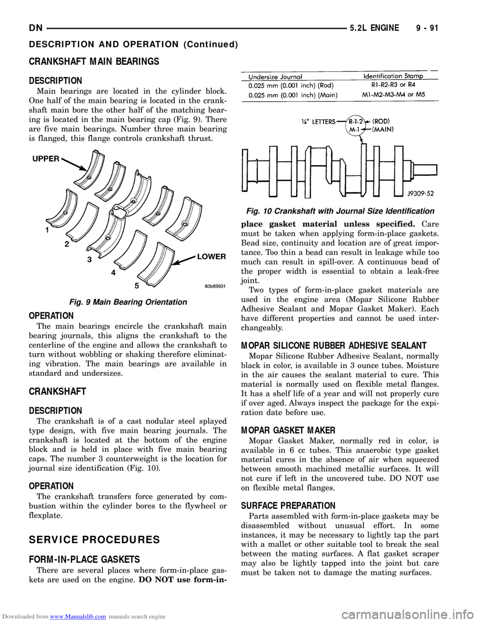
Main bearings are located in the cylinder block.
One half of the main bearing is located in the crank-
shaft main bore the other half of the matching bear-
ing is located in the main bearing cap (Fig. 9). There
are five main bearings. Number three main bearing
is flanged, this flange controls crankshaft thrust.
OPERATION
The main bearings encircle the crankshaft main
bearing journals, this aligns the crankshaft to the
centerline of the engine and allows the crankshaft to
turn without wobbling or shaking therefore eliminat-
ing vibration. The main bearings are available in
standard and undersizes.
CRANKSHAFT
DESCRIPTION
The crankshaft is of a cast nodular steel splayed
type design, with five main bearing journals. The
crankshaft is located at the bottom of the engine
block and is held in place with five main bearing
caps. The number 3 counterweight is the location for
journal size identification (Fig. 10).
OPERATION
The crankshaft transfers force generated by com-
bustion within the cylinder bores to the flywheel or
flexplate.
SERVICE PROCEDURES
FORM-IN-PLACE GASKETS
There are several places where form-in-place gas-
kets are used on the engine.DO NOT use form-in-place gasket material unless specified.Care
must be taken when applying form-in-place gaskets.
Bead size, continuity and location are of great impor-
tance. Too thin a bead can result in leakage while too
much can result in spill-over. A continuous bead of
the proper width is essential to obtain a leak-free
joint.
Two types of form-in-place gasket materials are
used in the engine area (Mopar Silicone Rubber
Adhesive Sealant and Mopar Gasket Maker). Each
have different properties and cannot be used inter-
changeably.
MOPAR SILICONE RUBBER ADHESIVE SEALANT
Mopar Silicone Rubber Adhesive Sealant, normally
black in color, is available in 3 ounce tubes. Moisture
in the air causes the sealant material to cure. This
material is normally used on flexible metal flanges.
It has a shelf life of a year and will not properly cure
if over aged. Always inspect the package for the expi-
ration date before use.
MOPAR GASKET MAKER
Mopar Gasket Maker, normally red in color, is
available in 6 cc tubes. This anaerobic type gasket
material cures in the absence of air when squeezed
between smooth machined metallic surfaces. It will
not cure if left in the uncovered tube. DO NOT use
on flexible metal flanges.
SURFACE PREPARATION
Parts assembled with form-in-place gaskets may be
disassembled without unusual effort. In some
instances, it may be necessary to lightly tap the part
with a mallet or other suitable tool to break the seal
between the mating surfaces. A flat gasket scraper
may also be lightly tapped into the joint but care
must be taken not to damage the mating surfaces.
Fig. 9 Main Bearing Orientation
Fig. 10 Crankshaft with Journal Size Identification
DN5.2L ENGINE 9 - 91
DESCRIPTION AND OPERATION (Continued)
Page 95 of 193
Downloaded from www.Manualslib.com manuals search engine (4) A controlled hone motor speed between 200 and
300 RPM is necessary to obtain the proper cross-
hatch angle. The number of up and down strokes per
minute can be regulated to get the desired 50É to 60É
angle. Faster up and down strokes increase the cross-
hatch angle.
(5) After honing, it is necessary that the block be
cleaned to remove all traces of abrasive. Use a brush
to wash parts with a solution of hot water and deter-
gent. Dry parts thoroughly. Use a clean, white, lint-
free cloth to check that the bore is clean. Oil the
bores after cleaning to prevent rusting.
HYDROSTATIC LOCK
When an engine is suspected of hydrostatic lock
(regardless of what caused the problem), follow the
steps below.
(1) Perform the Fuel Pressure Release Procedure
(refer to Group 14, Fuel System).
(2) Disconnect the battery negative cable.
(3) Inspect air cleaner, induction system and
intake manifold to ensure system is dry and clear of
foreign material.
(4) Place a shop towel around the spark plugs to
catch any fluid that may possibly be under pressure
in the cylinder head. Remove the plugs from the
engine.
CAUTION: DO NOT use the starter motor to rotate
the crankshaft. Severe damage could occur.
(5) With all spark plugs removed, rotate the crank-
shaft using a breaker bar and socket.
(6) Identify the fluid in the cylinders (i.e. coolant,
fuel, oil, etc.).
(7) Make sure all fluid has been removed from the
cylinders.
(8) Repair engine or components as necessary to
prevent this problem from occurring again.
(9) Squirt engine oil into the cylinders to lubricate
the walls. This will prevent damage on restart.
(10) Install new spark plugs.
(11) Drain engine oil. Remove and discard the oil
filter.
(12) Install the drain plug. Tighten the plug to 34
N´m (25 ft. lbs.) torque.
(13) Install a new oil filter.
(14) Fill engine crankcase with the specified
amount and grade of oil.
(15) Connect the negative cable to the battery.
(16) Start the engine and check for any leaks.
VALVE TIMING
(1) Turn crankshaft until the No.6 exhaust valve is
closing and No.6 intake valve is opening.(2) Insert a 6.350 mm (1/4 inch) spacer between
rocker arm pad and stem tip of No.1 intake valve.
Allow spring load to bleed tappet down giving in
effect a solid tappet.
(3) Install a dial indicator so plunger contacts
valve spring retainer as nearly perpendicular as pos-
sible. Zero the indicator.
(4) Rotate the crankshaft clockwise (normal run-
ning direction) until the valve has lifted 0.863 mm
(0.034 inch). The timing of the crankshaft should
now read from 10É before top dead center to 2É after
top dead center. Remove spacer.
CAUTION: DO NOT turn crankshaft any further
clockwise as valve spring might bottom and result
in serious damage.
If reading is not within specified limits:
²Check sprocket index marks.
²Inspect timing chain for wear.
²Check accuracy of DC mark on timing indicator.
VALVE SERVICE
VALVE CLEANING
Clean valves thoroughly. Discard burned, warped
and cracked valves.
Remove carbon and varnish deposits from inside of
valve guides with a reliable guide cleaner.
VALVE INSPECTION
Measure valve stems for wear. If wear exceeds
0.051 mm (0.002 inch), replace the valve.
VALVE GUIDES
Measure valve stem guide clearance as follows:
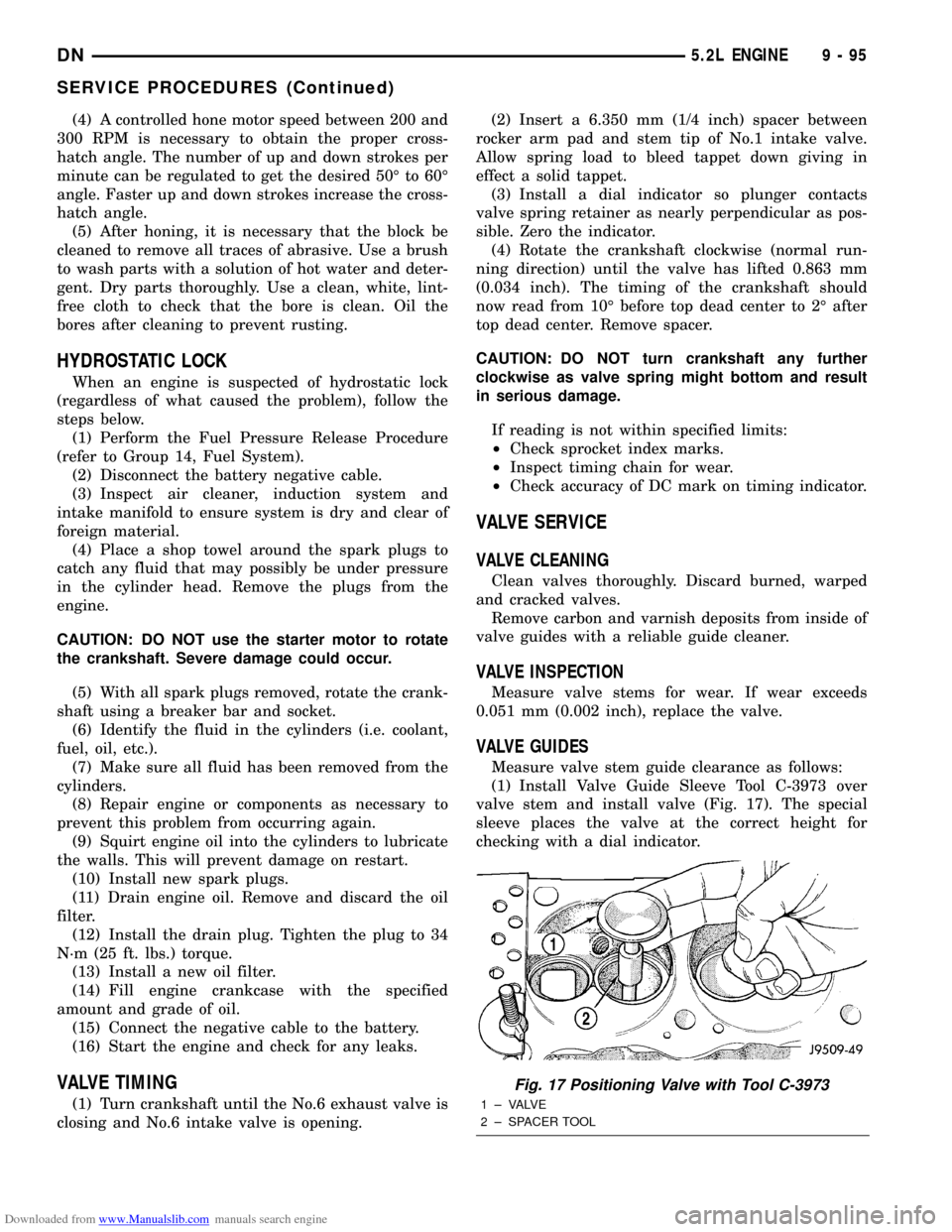
(1) Install Valve Guide Sleeve Tool C-3973 over
valve stem and install valve (Fig. 17). The special
sleeve places the valve at the correct height for
checking with a dial indicator.
Fig. 17 Positioning Valve with Tool C-3973
1 ± VALVE
2 ± SPACER TOOL
DN5.2L ENGINE 9 - 95
SERVICE PROCEDURES (Continued)
Page 117 of 193
Downloaded from www.Manualslib.com manuals search engine PISTON AND CONNECTING ROD ASSEMBLY
REMOVAL
(1) Remove the engine from the vehicle.
(2) Remove the cylinder head.
(3) Remove the oil pan.
(4) Remove top ridge of cylinder bores with a reli-
able ridge reamer before removing pistons from cyl-
inder block. Be sure to keep tops of pistons covered
during this operation.
(5) Be sure the connecting rod and connecting rod
cap are identified with the cylinder number. Remove
connecting rod cap. Install connecting rod bolt guide
set on connecting rod bolts.
(6) Pistons and connecting rods must be removed
from top of cylinder block. When removing piston and
connecting rod assemblies, rotate crankshaft to cen-
ter the connecting rod in the cylinder bore and at
BDC.Be careful not to nick crankshaft journals.
(7) After removal, install bearing cap on the mat-
ing rod.
INSTALLATION
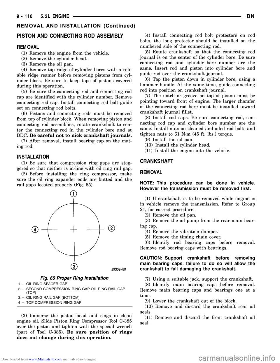
(1) Be sure that compression ring gaps are stag-
gered so that neither is in-line with oil ring rail gap.
(2) Before installing the ring compressor, make
sure the oil ring expander ends are butted and the
rail gaps located properly (Fig. 65).
(3) Immerse the piston head and rings in clean
engine oil. Slide Piston Ring Compressor Tool C-385
over the piston and tighten with the special wrench
(part of Tool C-385).Be sure position of rings
does not change during this operation.(4) Install connecting rod bolt protectors on rod
bolts, the long protector should be installed on the
numbered side of the connecting rod.
(5) Rotate crankshaft so that the connecting rod
journal is on the center of the cylinder bore. Be sure
connecting rod and cylinder bore number are the
same. Insert rod and piston into cylinder bore and
guide rod over the crankshaft journal.
(6) Tap the piston down in cylinder bore, using a
hammer handle. At the same time, guide connecting
rod into position on crankshaft journal.
(7) The notch or groove on top of piston must be
pointing toward front of engine. The larger chamfer
of the connecting rod bore must be installed toward
crankshaft journal fillet.
(8) Install rod caps. Be sure connecting rod, con-
necting rod cap and cylinder bore number are the
same. Install nuts on cleaned and oiled rod bolts and
tighten nuts to 61 N´m (45 ft. lbs.) torque.
(9) Install the oil pan.
(10) Install the cylinder head.
(11) Install the engine into the vehicle.CRANKSHAFT
REMOVAL
NOTE: This procedure can be done in vehicle.
However the transmission must be removed first.
(1) If crankshaft is to be removed while engine is
in vehicle remove the transmission. Refer to Group
21, for correct procedure.
(2) Remove the oil pan.
(3) Remove the oil pump from the rear main bear-
ing cap.
(4) Remove the vibration damper.
(5) Remove the timing chain cover.
(6) Identify rod bearing caps before removal.
Remove rod bearing caps with bearings.
CAUTION: Support crankshaft before removing
main bearing caps. failure to do so will allow the
crankshaft to fall damaging the crankshaft.
(7) Using a suitable jack, support the crankshaft.
(8) Identify main bearing caps before removal.
Remove main bearing caps and bearings one at a
time.
(9) Lower the crankshaft out of the block.
(10) Remove and discard the crankshaft rear oil
seals.
(11) Remove and discard the front crankshaft oil
seal.
Fig. 65 Proper Ring Installation
1 ± OIL RING SPACER GAP
2 ± SECOND COMPRESSION RING GAP OIL RING RAIL GAP
(TOP)
3 ± OIL RING RAIL GAP (BOTTOM)
4 ± TOP COMPRESSION RING GAP
9 - 116 5.2L ENGINEDN
REMOVAL AND INSTALLATION (Continued)
Page 137 of 193
Downloaded from www.Manualslib.com manuals search engine DESCRIPTION AND OPERATION
ENGINE
DESCRIPTION
The 5.9 Liter (360 CID) eight-cylinder engine is a
V-Type lightweight, single cam, overhead valve
engine with hydraulic roller tappets. This engine is
designed for unleaded fuel.
The engine lubrication system consists of a rotor
type oil pump and a full flow oil filter.
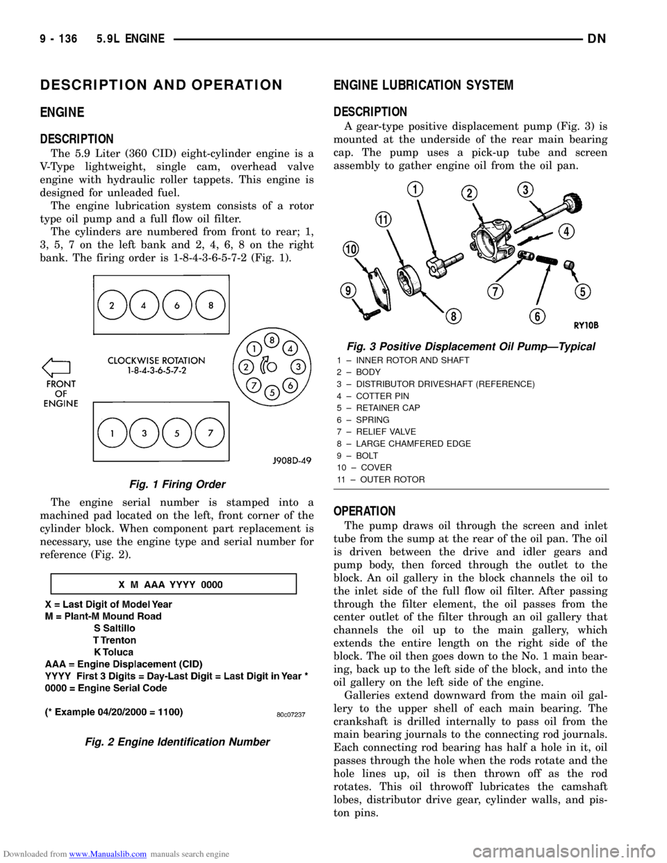
The cylinders are numbered from front to rear; 1,
3, 5, 7 on the left bank and 2, 4, 6, 8 on the right
bank. The firing order is 1-8-4-3-6-5-7-2 (Fig. 1).
The engine serial number is stamped into a
machined pad located on the left, front corner of the
cylinder block. When component part replacement is
necessary, use the engine type and serial number for
reference (Fig. 2).
ENGINE LUBRICATION SYSTEM
DESCRIPTION
A gear-type positive displacement pump (Fig. 3) is
mounted at the underside of the rear main bearing
cap. The pump uses a pick-up tube and screen
assembly to gather engine oil from the oil pan.
OPERATION
The pump draws oil through the screen and inlet
tube from the sump at the rear of the oil pan. The oil
is driven between the drive and idler gears and
pump body, then forced through the outlet to the
block. An oil gallery in the block channels the oil to
the inlet side of the full flow oil filter. After passing
through the filter element, the oil passes from the
center outlet of the filter through an oil gallery that
channels the oil up to the main gallery, which
extends the entire length on the right side of the
block. The oil then goes down to the No. 1 main bear-
ing, back up to the left side of the block, and into the
oil gallery on the left side of the engine.
Galleries extend downward from the main oil gal-
lery to the upper shell of each main bearing. The
crankshaft is drilled internally to pass oil from the
main bearing journals to the connecting rod journals.
Each connecting rod bearing has half a hole in it, oil
passes through the hole when the rods rotate and the
hole lines up, oil is then thrown off as the rod
rotates. This oil throwoff lubricates the camshaft
lobes, distributor drive gear, cylinder walls, and pis-
ton pins.
Fig. 1 Firing Order
Fig. 2 Engine Identification Number
Fig. 3 Positive Displacement Oil PumpÐTypical
1 ± INNER ROTOR AND SHAFT
2 ± BODY
3 ± DISTRIBUTOR DRIVESHAFT (REFERENCE)
4 ± COTTER PIN
5 ± RETAINER CAP
6 ± SPRING
7 ± RELIEF VALVE
8 ± LARGE CHAMFERED EDGE
9 ± BOLT
10 ± COVER
11 ± OUTER ROTOR
9 - 136 5.9L ENGINEDN
Page 141 of 193
Downloaded from www.Manualslib.com manuals search engine CYLINDER HEAD COVER GASKET
DESCRIPTION
The cylinder head cover gasket is a steel-backed
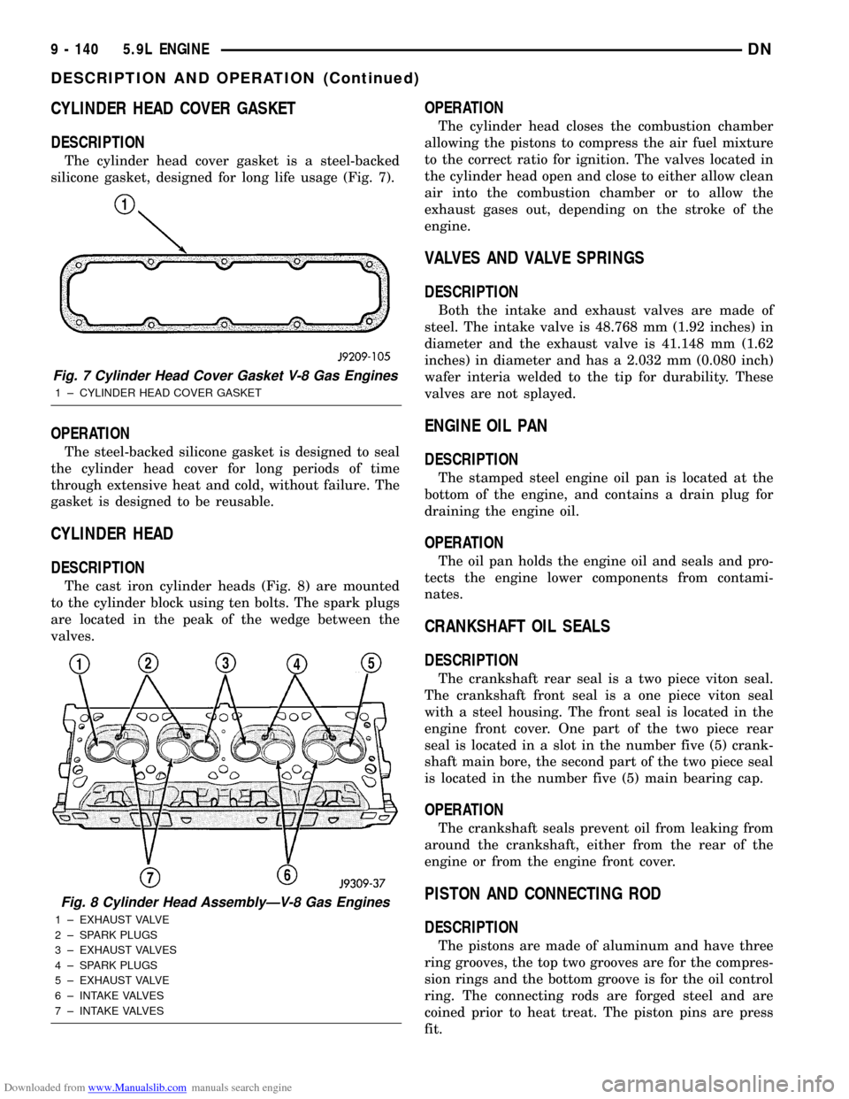
silicone gasket, designed for long life usage (Fig. 7).
OPERATION
The steel-backed silicone gasket is designed to seal
the cylinder head cover for long periods of time
through extensive heat and cold, without failure. The
gasket is designed to be reusable.
CYLINDER HEAD
DESCRIPTION
The cast iron cylinder heads (Fig. 8) are mounted
to the cylinder block using ten bolts. The spark plugs
are located in the peak of the wedge between the
valves.
OPERATION
The cylinder head closes the combustion chamber
allowing the pistons to compress the air fuel mixture
to the correct ratio for ignition. The valves located in
the cylinder head open and close to either allow clean
air into the combustion chamber or to allow the
exhaust gases out, depending on the stroke of the
engine.
VALVES AND VALVE SPRINGS
DESCRIPTION
Both the intake and exhaust valves are made of
steel. The intake valve is 48.768 mm (1.92 inches) in
diameter and the exhaust valve is 41.148 mm (1.62
inches) in diameter and has a 2.032 mm (0.080 inch)
wafer interia welded to the tip for durability. These
valves are not splayed.
ENGINE OIL PAN
DESCRIPTION
The stamped steel engine oil pan is located at the
bottom of the engine, and contains a drain plug for
draining the engine oil.
OPERATION
The oil pan holds the engine oil and seals and pro-
tects the engine lower components from contami-
nates.
CRANKSHAFT OIL SEALS
DESCRIPTION
The crankshaft rear seal is a two piece viton seal.
The crankshaft front seal is a one piece viton seal
with a steel housing. The front seal is located in the
engine front cover. One part of the two piece rear
seal is located in a slot in the number five (5) crank-
shaft main bore, the second part of the two piece seal
is located in the number five (5) main bearing cap.
OPERATION
The crankshaft seals prevent oil from leaking from
around the crankshaft, either from the rear of the
engine or from the engine front cover.
PISTON AND CONNECTING ROD
DESCRIPTION
The pistons are made of aluminum and have three
ring grooves, the top two grooves are for the compres-
sion rings and the bottom groove is for the oil control
ring. The connecting rods are forged steel and are
coined prior to heat treat. The piston pins are press
fit.
Fig. 7 Cylinder Head Cover Gasket V-8 Gas Engines
1 ± CYLINDER HEAD COVER GASKET
Fig. 8 Cylinder Head AssemblyÐV-8 Gas Engines
1 ± EXHAUST VALVE
2 ± SPARK PLUGS
3 ± EXHAUST VALVES
4 ± SPARK PLUGS
5 ± EXHAUST VALVE
6 ± INTAKE VALVES
7 ± INTAKE VALVES
9 - 140 5.9L ENGINEDN
DESCRIPTION AND OPERATION (Continued)
Page 153 of 193
Downloaded from www.Manualslib.com manuals search engine Damaged or worn threads can be repaired. Essen-
tially, this repair consists of:
²Drilling out worn or damaged threads.
²Tapping the hole with a special Heli-Coil Tap, or
equivalent.
²Installing an insert into the tapped hole to bring
the hole back to its original thread size.
CYLINDER BOREÐHONING
Before honing, stuff plenty of clean shop towels
under the bores and over the crankshaft to keep
abrasive materials from entering the crankshaft
area.
(1) Used carefully, the Cylinder Bore Sizing Hone
C-823, equipped with 220 grit stones, is the best tool
for this job. In addition to deglazing, it will reduce
taper and out-of-round, as well as removing light
scuffing, scoring and scratches. Usually, a few strokes
will clean up a bore and maintain the required lim-
its.
CAUTION: DO NOT use rigid type hones to remove
cylinder wall glaze.
(2) Deglazing of the cylinder walls may be done if
the cylinder bore is straight and round. Use a cylin-
der surfacing hone, Honing Tool C-3501, equipped
with 280 grit stones (C-3501-3810). about 20-60
strokes, depending on the bore condition, will be suf-
ficient to provide a satisfactory surface. Using honing
oil C-3501-3880, or a light honing oil, available from
major oil distributors.
CAUTION: DO NOT use engine or transmission oil,
mineral spirits, or kerosene.
(3) Honing should be done by moving the hone up
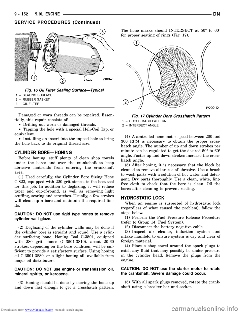
and down fast enough to get a crosshatch pattern.The hone marks should INTERSECT at 50É to 60É
for proper seating of rings (Fig. 17).
(4) A controlled hone motor speed between 200 and
300 RPM is necessary to obtain the proper cross-
hatch angle. The number of up and down strokes per
minute can be regulated to get the desired 50É to 60É
angle. Faster up and down strokes increase the cross-
hatch angle.
(5) After honing, it is necessary that the block be
cleaned to remove all traces of abrasive. Use a brush
to wash parts with a solution of hot water and deter-
gent. Dry parts thoroughly. Use a clean, white, lint-
free cloth to check that the bore is clean. Oil the
bores after cleaning to prevent rusting.
HYDROSTATIC LOCK
When an engine is suspected of hydrostatic lock
(regardless of what caused the problem), follow the
steps below.
(1) Perform the Fuel Pressure Release Procedure
(refer to Group 14, Fuel System).
(2) Disconnect the battery negative cable.
(3) Inspect air cleaner, induction system and
intake manifold to ensure system is dry and clear of
foreign material.
(4) Place a shop towel around the spark plugs to
catch any fluid that may possibly be under pressure
in the cylinder head. Remove the plugs from the
engine.
CAUTION: DO NOT use the starter motor to rotate
the crankshaft. Severe damage could occur.
(5) With all spark plugs removed, rotate the crank-
shaft using a breaker bar and socket.
Fig. 16 Oil Filter Sealing SurfaceÐTypical
1 ± SEALING SURFACE
2 ± RUBBER GASKET
3 ± OIL FILTER
Fig. 17 Cylinder Bore Crosshatch Pattern
1 ± CROSSHATCH PATTERN
2 ± INTERSECT ANGLE
9 - 152 5.9L ENGINEDN
SERVICE PROCEDURES (Continued)