Pin out chart DODGE DURANGO 2000 1.G Workshop Manual
[x] Cancel search | Manufacturer: DODGE, Model Year: 2000, Model line: DURANGO, Model: DODGE DURANGO 2000 1.GPages: 193, PDF Size: 5.65 MB
Page 5 of 193
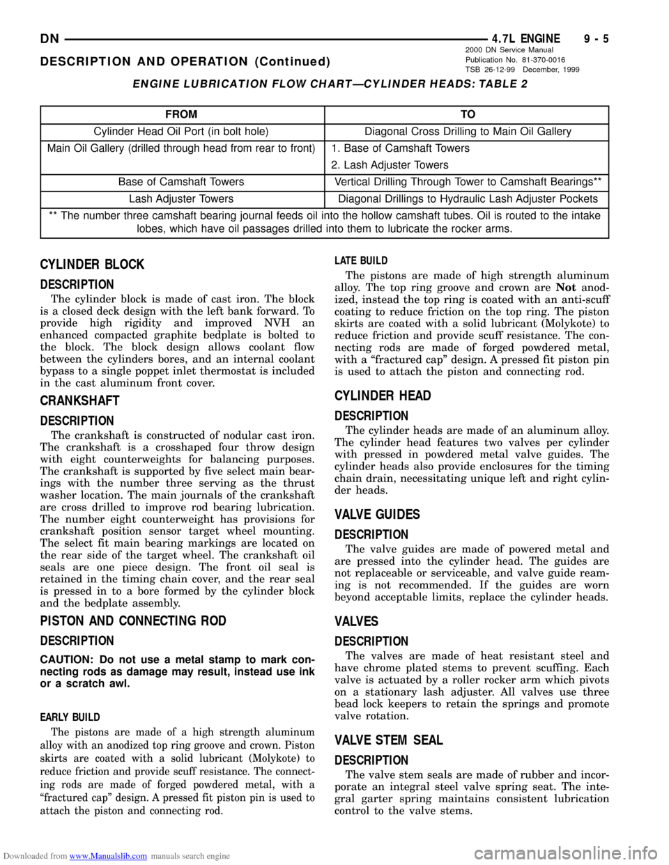
Downloaded from www.Manualslib.com manuals search engine ENGINE LUBRICATION FLOW CHARTÐCYLINDER HEADS: TABLE 2
FROM TO
Cylinder Head Oil Port (in bolt hole) Diagonal Cross Drilling to Main Oil Gallery
Main Oil Gallery (drilled through head from rear to front)1. Base of Camshaft Towers
2. Lash Adjuster Towers
Base of Camshaft Towers Vertical Drilling Through Tower to Camshaft Bearings**
Lash Adjuster Towers Diagonal Drillings to Hydraulic Lash Adjuster Pockets
** The number three camshaft bearing journal feeds oil into the hollow camshaft tubes. Oil is routed to the intake
lobes, which have oil passages drilled into them to lubricate the rocker arms.
CYLINDER BLOCK
DESCRIPTION
The cylinder block is made of cast iron. The block
is a closed deck design with the left bank forward. To
provide high rigidity and improved NVH an
enhanced compacted graphite bedplate is bolted to
the block. The block design allows coolant flow
between the cylinders bores, and an internal coolant
bypass to a single poppet inlet thermostat is included
in the cast aluminum front cover.
CRANKSHAFT
DESCRIPTION
The crankshaft is constructed of nodular cast iron.
The crankshaft is a crosshaped four throw design
with eight counterweights for balancing purposes.
The crankshaft is supported by five select main bear-
ings with the number three serving as the thrust
washer location. The main journals of the crankshaft
are cross drilled to improve rod bearing lubrication.
The number eight counterweight has provisions for
crankshaft position sensor target wheel mounting.
The select fit main bearing markings are located on
the rear side of the target wheel. The crankshaft oil
seals are one piece design. The front oil seal is
retained in the timing chain cover, and the rear seal
is pressed in to a bore formed by the cylinder block
and the bedplate assembly.
PISTON AND CONNECTING ROD
DESCRIPTION
CAUTION: Do not use a metal stamp to mark con-
necting rods as damage may result, instead use ink
or a scratch awl.
EARLY BUILD
The pistons are made of a high strength aluminum
alloy with an anodized top ring groove and crown. Piston
skirts are coated with a solid lubricant (Molykote) to
reduce friction and provide scuff resistance. The connect-
ing rods are made of forged powdered metal, with a
ªfractured capº design. A pressed fit piston pin is used to
attach the piston and connecting rod.
LATE BUILD
The pistons are made of high strength aluminum
alloy. The top ring groove and crown areNotanod-
ized, instead the top ring is coated with an anti-scuff
coating to reduce friction on the top ring. The piston
skirts are coated with a solid lubricant (Molykote) to
reduce friction and provide scuff resistance. The con-
necting rods are made of forged powdered metal,
with a ªfractured capº design. A pressed fit piston pin
is used to attach the piston and connecting rod.
CYLINDER HEAD
DESCRIPTION
The cylinder heads are made of an aluminum alloy.
The cylinder head features two valves per cylinder
with pressed in powdered metal valve guides. The
cylinder heads also provide enclosures for the timing
chain drain, necessitating unique left and right cylin-
der heads.
VALVE GUIDES
DESCRIPTION
The valve guides are made of powered metal and
are pressed into the cylinder head. The guides are
not replaceable or serviceable, and valve guide ream-
ing is not recommended. If the guides are worn
beyond acceptable limits, replace the cylinder heads.
VALVES
DESCRIPTION
The valves are made of heat resistant steel and
have chrome plated stems to prevent scuffing. Each
valve is actuated by a roller rocker arm which pivots
on a stationary lash adjuster. All valves use three
bead lock keepers to retain the springs and promote
valve rotation.
VALVE STEM SEAL
DESCRIPTION
The valve stem seals are made of rubber and incor-
porate an integral steel valve spring seat. The inte-
gral garter spring maintains consistent lubrication
control to the valve stems.
DN4.7L ENGINE 9 - 5
DESCRIPTION AND OPERATION (Continued)
2000 DN Service Manual
Publication No. 81-370-0016
TSB 26-12-99 December, 1999
Page 13 of 193
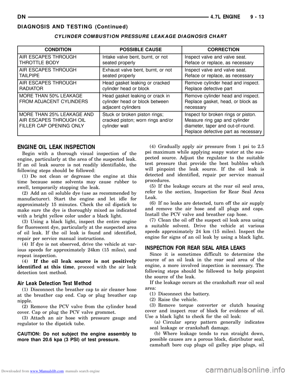
Downloaded from www.Manualslib.com manuals search engine CYLINDER COMBUSTION PRESSURE LEAKAGE DIAGNOSIS CHART
CONDITION POSSIBLE CAUSE CORRECTION
AIR ESCAPES THROUGH
THROTTLE BODYIntake valve bent, burnt, or not
seated properlyInspect valve and valve seat.
Reface or replace, as necessary
AIR ESCAPES THROUGH
TAILPIPEExhaust valve bent, burnt, or not
seated properlyInspect valve and valve seat.
Reface or replace, as necessary
AIR ESCAPES THROUGH
RADIATORHead gasket leaking or cracked
cylinder head or blockRemove cylinder head and inspect.
Replace defective part
MORE THAN 50% LEAKAGE
FROM ADJACENT CYLINDERSHead gasket leaking or crack in
cylinder head or block between
adjacent cylindersRemove cylinder head and inspect.
Replace gasket, head, or block as
necessary
MORE THAN 25% LEAKAGE AND
AIR ESCAPES THROUGH OIL
FILLER CAP OPENING ONLYStuck or broken piston rings;
cracked piston; worn rings and/or
cylinder wallInspect for broken rings or piston.
Measure ring gap and cylinder
diameter, taper and out-of-round.
Replace defective part as necessary
ENGINE OIL LEAK INSPECTION
Begin with a thorough visual inspection of the
engine, particularly at the area of the suspected leak.
If an oil leak source is not readily identifiable, the
following steps should be followed:
(1) Do not clean or degrease the engine at this
time because some solvents may cause rubber to
swell, temporarily stopping the leak.
(2) Add an oil soluble dye (use as recommended by
manufacturer). Start the engine and let idle for
approximately 15 minutes. Check the oil dipstick to
make sure the dye is thoroughly mixed as indicated
with a bright yellow color under a black light.
(3) Using a black light, inspect the entire engine
for fluorescent dye, particularly at the suspected area
of oil leak. If the oil leak is found and identified,
repair per service manual instructions.
(4) If dye is not observed, drive the vehicle at var-
ious speeds for approximately 24km (15 miles), and
repeat inspection.
(4)If the oil leak source is not positively
identified at this time, proceed with the air leak
detection test method.
Air Leak Detection Test Method
(1) Disconnect the breather cap to air cleaner hose
at the breather cap end. Cap or plug breather cap
nipple.
(2) Remove the PCV valve from the cylinder head
cover. Cap or plug the PCV valve grommet.
(3) Attach an air hose with pressure gauge and
regulator to the dipstick tube.
CAUTION: Do not subject the engine assembly to
more than 20.6 kpa (3 PSI) of test pressure.(4) Gradually apply air pressure from 1 psi to 2.5
psi maximum while applying soapy water at the sus-
pected source. Adjust the regulator to the suitable
test pressure that provide the best bubbles which
will pinpoint the leak source. If the oil leak is
detected and identified, repair per service manual
procedures.
(5) If the leakage occurs at the rear oil seal area,
refer to the section, Inspection for Rear Seal Area
Leak.
(6) If no leaks are detected, turn off the air supply
and remove the air hose and all plugs and caps.
Install the PCV valve and breather cap hose.
(7) Clean the oil off the suspect oil leak area using
a suitable solvent. Drive the vehicle at various
speeds approximately 24 km (15 miles). Inspect the
engine for signs of an oil leak by using a black light.
INSPECTION FOR REAR SEAL AREA LEAKS
Since it is sometimes difficult to determine the
source of an oil leak in the rear seal area of the
engine, a more involved inspection is necessary. The
following steps should be followed to help pinpoint
the source of the leak.
If the leakage occurs at the crankshaft rear oil seal
area:
(1) Disconnect the battery.
(2) Raise the vehicle.
(3) Remove torque converter or clutch housing
cover and inspect rear of block for evidence of oil.
Use a black light to check for the oil leak:
(a) Circular spray pattern generally indicates
seal leakage or crankshaft damage.
(b) Where leakage tends to run straight down,
possible causes are a porous block, distributor seal,
camshaft bore cup plugs oil galley pipe plugs, oil
DN4.7L ENGINE 9 - 13
DIAGNOSIS AND TESTING (Continued)
Page 61 of 193
Downloaded from www.Manualslib.com manuals search engine INSTALLATION
(1) Lubricate camshaft journals with clean engine
oil.
NOTE: Position the right side camshaft so that the
camshaft sprocket dowel is near the 10 o'clock
position, This will place the camshaft at the neutral
position easing the installation of the camshaft
bearing caps.
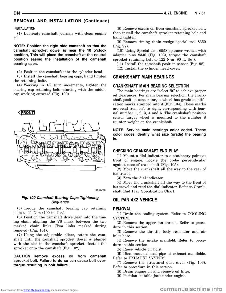
(2) Position the camshaft into the cylinder head.
(3) Install the camshaft bearing caps, hand tighten
the retaining bolts.
(4) Working in 1/2 turn increments, tighten the
bearing cap retaining bolts starting with the middle
cap working outward (Fig. 100).
(5) Torque the camshaft bearing cap retaining
bolts to 11 N´m (100 in. lbs.).
(6) Position the camshaft drive gear into the tim-
ing chain aligning the V8 mark between the two
marked chain links (Two links marked during
removal) (Fig. 101).
(7) Using the adjustable pliers, rotate the cam-
shaft until the camshaft sprocket dowel is aligned
with the slot in the camshaft sprocket. Install the
sprocket onto the camshaft (Fig. 102).
CAUTION: Remove excess oil from camshaft
sprocket bolt. Failure to do so can cause bolt over-
torque resulting in bolt failure.(8) Remove excess oil from camshaft sprocket bolt,
then install the camshaft sprocket retaining bolt and
hand tighten.
(9) Remove timing chain wedge special tool 8350
(Fig. 97).
(10) Using Special Tool 6958 spanner wrench with
adapter pins 8346 (Fig. 103), torque the camshaft
sprocket retaining bolt to 122 N´m (90 ft. lbs.).
(11) Install the camshaft position sensor (Fig. 98).
(12) Install the cylinder head cover.
CRANKSHAFT MAIN BEARINGS
CRANKSHAFT MAIN BEARING SELECTION
The main bearings are ªselect fitº to achieve proper
oil clearances. For main bearing selection, the crank-
shaft position sensor target wheel has grade identifi-
cation marks stamped into it (Fig. 104). These marks
are read from left to right, corresponding with jour-
nal number 1, 2, 3, 4 and 5. The crankshaft position
sensor target wheel is mounted to the number 8
counter weight on the crankshaft.
NOTE: Service main bearings color coded. These
color codes identify what size (grade) the bearing
is.
CHECKING CRANKSHAFT END PLAY
(1) Mount a dial indicator to a stationary point at
front of engine. Locate the probe perpendicular
against nose of crankshaft (Fig. 105).
(2) Move the crankshaft all the way to the rear of
it's travel.
(3) Zero the dial indicator.
(4) Move the crankshaft all the way to the front of
it's travel and read the dial indicator. Refer to Crank-
shaft End Play Specification Chart.
OIL PAN 4X2 VEHICLE
REMOVAL
(1) Drain the cooling system. Refer to COOLING
SYSTEM.
(2) Remove the upper fan shroud. Refer to proce-
dure in this section.
(3) Remove the throttle body resonator and air
inlet hose.
(4) Remove the intake manifold. Refer to proce-
dure in this section.
(5) Raise vehicle on hoist.
(6) Disconnect exhaust pipe at exhaust manifolds.
Refer to EXHAUST SYSTEM.
(7) Remove the structural dust cover (Fig. 106).
Refer to procedure in this section.
(8) Drain engine oil and remove oil filter.
(9) Position suitable jack under engine.
Fig. 100 Camshaft Bearing Caps Tightening
Sequence
DN4.7L ENGINE 9 - 61
REMOVAL AND INSTALLATION (Continued)
Page 126 of 193
Downloaded from www.Manualslib.com manuals search engine Clean oil pan in solvent and wipe dry with a clean
cloth.
Clean oil screen and pipe thoroughly in clean sol-
vent. Inspect condition of screen.
INSPECTION
Inspect oil drain plug and plug hole for stripped or
damaged threads. Repair as necessary.
Inspect oil pan mounting flange for bends or distor-
tion. Straighten flange, if necessary.
OIL PUMP
INSPECTION
Mating surface of the oil pump cover should be
smooth. Replace pump assembly if cover is scratched
or grooved.
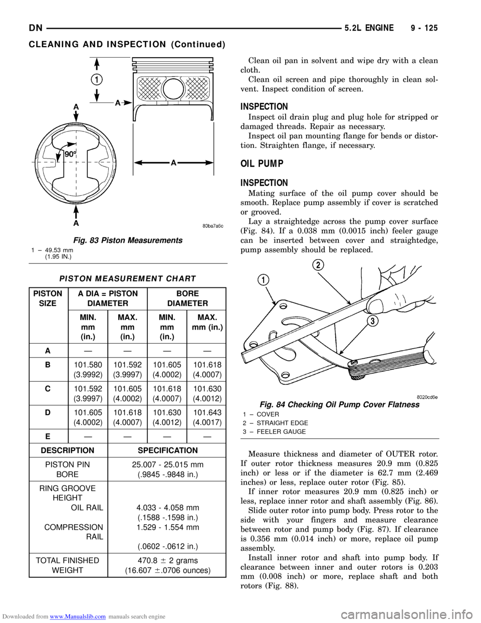
Lay a straightedge across the pump cover surface
(Fig. 84). If a 0.038 mm (0.0015 inch) feeler gauge
can be inserted between cover and straightedge,
pump assembly should be replaced.
Measure thickness and diameter of OUTER rotor.
If outer rotor thickness measures 20.9 mm (0.825
inch) or less or if the diameter is 62.7 mm (2.469
inches) or less, replace outer rotor (Fig. 85).
If inner rotor measures 20.9 mm (0.825 inch) or
less, replace inner rotor and shaft assembly (Fig. 86).
Slide outer rotor into pump body. Press rotor to the
side with your fingers and measure clearance
between rotor and pump body (Fig. 87). If clearance
is 0.356 mm (0.014 inch) or more, replace oil pump
assembly.
Install inner rotor and shaft into pump body. If
clearance between inner and outer rotors is 0.203
mm (0.008 inch) or more, replace shaft and both
rotors (Fig. 88).
Fig. 83 Piston Measurements
1 ± 49.53 mm
(1.95 IN.)
PISTON MEASUREMENT CHART
PISTON A DIA = PISTON BORE
SIZE DIAMETER DIAMETER
MIN. MAX. MIN. MAX.
mm
(in.)mm
(in.)mm
(in.)mm (in.)
AÐÐÐ Ð
B101.580 101.592 101.605 101.618
(3.9992) (3.9997) (4.0002) (4.0007)
C101.592 101.605 101.618 101.630
(3.9997) (4.0002) (4.0007) (4.0012)
D101.605 101.618 101.630 101.643
(4.0002) (4.0007) (4.0012) (4.0017)
EÐÐÐ Ð
DESCRIPTION SPECIFICATION
PISTON PIN 25.007 - 25.015 mm
BORE (.9845 -.9848 in.)
RING GROOVE
HEIGHT
OIL RAIL 4.033 - 4.058 mm
(.1588 -.1598 in.)
COMPRESSION
RAIL1.529 - 1.554 mm
(.0602 -.0612 in.)
TOTAL FINISHED 470.862 grams
WEIGHT (16.6076.0706 ounces)
Fig. 84 Checking Oil Pump Cover Flatness
1 ± COVER
2 ± STRAIGHT EDGE
3 ± FEELER GAUGE
DN5.2L ENGINE 9 - 125
CLEANING AND INSPECTION (Continued)
Page 132 of 193
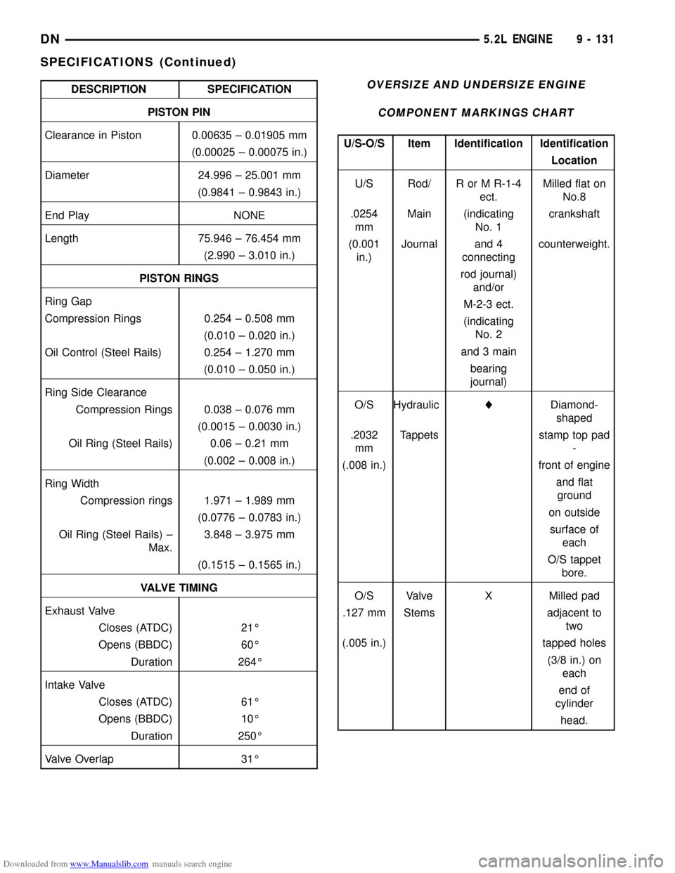
Downloaded from www.Manualslib.com manuals search engine DESCRIPTION SPECIFICATION
PISTON PIN
Clearance in Piston 0.00635 ± 0.01905 mm
(0.00025 ± 0.00075 in.)
Diameter 24.996 ± 25.001 mm
(0.9841 ± 0.9843 in.)
End Play NONE
Length 75.946 ± 76.454 mm
(2.990 ± 3.010 in.)
PISTON RINGS
Ring Gap
Compression Rings 0.254 ± 0.508 mm
(0.010 ± 0.020 in.)
Oil Control (Steel Rails) 0.254 ± 1.270 mm
(0.010 ± 0.050 in.)
Ring Side Clearance
Compression Rings 0.038 ± 0.076 mm
(0.0015 ± 0.0030 in.)
Oil Ring (Steel Rails) 0.06 ± 0.21 mm
(0.002 ± 0.008 in.)
Ring Width
Compression rings 1.971 ± 1.989 mm
(0.0776 ± 0.0783 in.)
Oil Ring (Steel Rails) ±
Max.3.848 ± 3.975 mm
(0.1515 ± 0.1565 in.)
VALVE TIMING
Exhaust Valve
Closes (ATDC) 21É
Opens (BBDC) 60É
Duration 264É
Intake Valve
Closes (ATDC) 61É
Opens (BBDC) 10É
Duration 250É
Valve Overlap 31ÉOVERSIZE AND UNDERSIZE ENGINE
COMPONENT MARKINGS CHART
U/S-O/S Item Identification Identification
Location
U/S Rod/ R or M R-1-4
ect.Milled flat on
No.8
.0254
mmMain (indicating
No. 1crankshaft
(0.001
in.)Journal and 4
connectingcounterweight.
rod journal)
and/or
M-2-3 ect.
(indicating
No. 2
and 3 main
bearing
journal)
O/S HydrauliclDiamond-
shaped
.2032
mmTappets stamp top pad
-
(.008 in.) front of engine
and flat
ground
on outside
surface of
each
O/S tappet
bore.
O/S Valve X Milled pad
.127 mm Stems adjacent to
two
(.005 in.) tapped holes
(3/8 in.) on
each
end of
cylinder
head.
DN5.2L ENGINE 9 - 131
SPECIFICATIONS (Continued)
Page 148 of 193
Downloaded from www.Manualslib.com manuals search engine All gauge pressure indications should be equal,
with no more than 25% leakage.
FOR EXAMPLE:At 552 kPa (80 psi) input pres-
sure, a minimum of 414 kPa (60 psi) should be main-
tained in the cylinder.
Refer to the Cylinder Combustion Pressure Leak-
age Test Diagnosis chart.
INSPECTION (ENGINE OIL LEAKS IN GENERAL)
Begin with a through visual inspection of the
engine, particularly at the area of the suspected leak.
If an oil leak source is not readily identifiable, the
following steps should be followed:
(1) Do not clean or degrease the engine at this
time because some solvents may cause rubber to
swell, temporarily stopping the leak.
(2) Add an oil-soluble dye (use as recommended by
manufacturer). Start the engine and let idle for
approximately 15 minutes. Check the oil dipstick to
be sure the dye is thoroughly mixed as indicated
with a bright yellow color under a black light source.
(3) Using a black light, inspect the entire engine
for fluorescent dye, particularly at the suspected area
of oil leak. If the oil leak is found and identified,
repair per service manual instructions.
(4) If dye is not observed, drive the vehicle at var-
ious speeds for approximately 24km (15 miles), and
repeat previous step.
(5) If the oil leak source is not positively identified
at this time, proceed with the air leak detection test
method as follows:
(6) Disconnect the breather cap to air cleaner hose
at the breather cap end. Cap or plug breather cap
nipple.
(7) Remove the PCV valve from the cylinder head
cover. Cap or plug the PCV valve grommet.
(8) Attach an air hose with pressure gauge and
regulator to the dipstick tube.
CAUTION: Do not subject the engine assembly to
more than 20.6 kpa (3 PSI) of test pressure.
(9) Gradually apply air pressure from 1 psi to 2.5
psi maximum while applying soapy water at the sus-
pected source. Adjust the regulator to the suitable
test pressure that provide the best bubbles which
will pinpoint the leak source. If the oil leak is
detected and identified, repair per service manual
procedures.
(10) If the leakage occurs at the rear oil seal area,
refer to the section, Inspection for Rear Seal Area
Leak.
(11) If no leaks are detected, turn off the air sup-
ply and remove the air hose and all plugs and caps.
Install the PCV valve and breather cap hose. Proceed
to next step.(12) Clean the oil off the suspect oil leak area
using a suitable solvent. Drive the vehicle at various
speeds approximately 24 km (15 miles). Inspect the
engine for signs of an oil leak by using a black light.
REAR SEAL AREA LEAKSÐINSPECTION
Since it is sometimes difficult to determine the
source of an oil leak in the rear seal area of the
engine, a more involved inspection is necessary. The
following steps should be followed to help pinpoint
the source of the leak.
If the leakage occurs at the crankshaft rear oil seal
area:
(1) Disconnect the battery.
(2) Raise the vehicle.
(3) Remove torque converter or clutch housing
cover and inspect rear of block for evidence of oil.
Use a black light to check for the oil leak:
(a) Circular spray pattern generally indicates
seal leakage or crankshaft damage.
(b) Where leakage tends to run straight down,
possible causes are a porous block, distributor seal,
camshaft bore cup plugs, oil galley pipe plugs, oil
filter runoff, and main bearing cap to cylinder
block mating surfaces. See Group 9, Engines, for
proper repair procedures of these items.
(4) If no leaks are detected, pressurized the crank-
case as outlined in the section, Inspection (Engine oil
Leaks in general)
CAUTION: Do not exceed 20.6 kPa (3 psi).
(5) If the leak is not detected, very slowly turn the
crankshaft and watch for leakage. If a leak is
detected between the crankshaft and seal while
slowly turning the crankshaft, it is possible the
crankshaft seal surface is damaged. The seal area on
the crankshaft could have minor nicks or scratches
that can be polished out with emery cloth.
CAUTION: Use extreme caution when crankshaft
polishing is necessary to remove minor nicks or
scratches. The crankshaft seal flange is specially
machined to complement the function of the rear oil
seal.
(6) For bubbles that remain steady with shaft
rotation, no further inspection can be done until dis-
assembled. Refer to the service DiagnosisÐMechani-
cal, under the Oil Leak row, for components
inspections on possible causes and corrections.
(7) After the oil leak root cause and appropriate
corrective action have been identified, Refer to Group
9, EnginesÐCrankshaft Rear Oil Seals, for proper
replacement procedures.
DN5.9L ENGINE 9 - 147
DIAGNOSIS AND TESTING (Continued)
Page 158 of 193
Downloaded from www.Manualslib.com manuals search engine CONNECTING ROD BEARINGSÐFITTING
Fit all rods on a bank until completed. DO NOT
alternate from one bank to another, because connect-
ing rods and pistons are not interchangeable from
one bank to another.
The bearing caps are not interchangeable and
should be marked at removal to ensure correct
assembly.
Each bearing cap has a small V-groove across the
parting face. When installing the lower bearing shell,
make certain that the V-groove in the shell is in line
with the V-groove in the cap. This provides lubrica-
tion of the cylinder wall in the opposite bank.The bearing shells must be installed so that the
tangs are in the machined grooves in the rods and
caps.
Limits of taper or out-of-round on any crankshaft
journals should be held to 0.025 mm (0.001 inch).
Bearings are available in 0.025 mm (0.001 inch),
0.051 mm (0.002 inch), 0.076 mm (0.003 inch), 0.254
mm (0.010 inch) and 0.305 mm (0.012 inch) under-
size.Install the bearings in pairs. DO NOT use a
new bearing half with an old bearing half. DO
NOT file the rods or bearing caps.
CRANKSHAFT MAIN BEARINGSÐFITTING
Bearing caps are not interchangeable and should
be marked at removal to ensure correct assembly.
Upper and lower bearing halves are NOT inter-
changeable. Lower main bearing halves of No.2 and 4
are interchangeable.
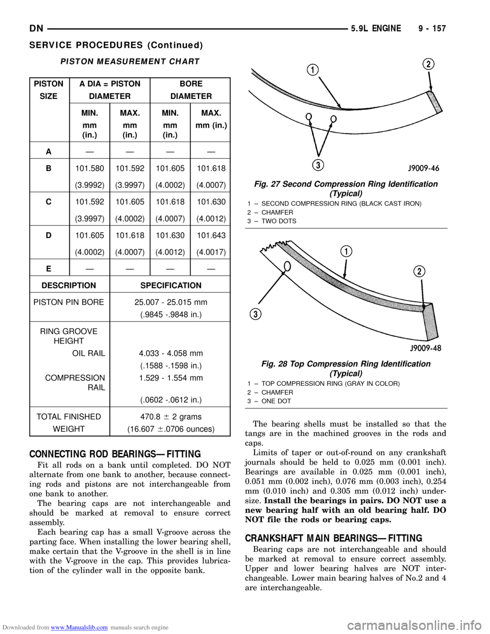
PISTON MEASUREMENT CHART
PISTON A DIA = PISTON BORE
SIZE DIAMETER DIAMETER
MIN. MAX. MIN. MAX.
mm
(in.)mm
(in.)mm
(in.)mm (in.)
AÐÐÐ Ð
B101.580 101.592 101.605 101.618
(3.9992) (3.9997) (4.0002) (4.0007)
C101.592 101.605 101.618 101.630
(3.9997) (4.0002) (4.0007) (4.0012)
D101.605 101.618 101.630 101.643
(4.0002) (4.0007) (4.0012) (4.0017)
EÐÐÐ Ð
DESCRIPTION SPECIFICATION
PISTON PIN BORE 25.007 - 25.015 mm
(.9845 -.9848 in.)
RING GROOVE
HEIGHT
OIL RAIL 4.033 - 4.058 mm
(.1588 -.1598 in.)
COMPRESSION
RAIL1.529 - 1.554 mm
(.0602 -.0612 in.)
TOTAL FINISHED 470.862 grams
WEIGHT (16.6076.0706 ounces)
Fig. 27 Second Compression Ring Identification
(Typical)
1 ± SECOND COMPRESSION RING (BLACK CAST IRON)
2 ± CHAMFER
3 ± TWO DOTS
Fig. 28 Top Compression Ring Identification
(Typical)
1 ± TOP COMPRESSION RING (GRAY IN COLOR)
2 ± CHAMFER
3 ± ONE DOT
DN5.9L ENGINE 9 - 157
SERVICE PROCEDURES (Continued)
Page 184 of 193
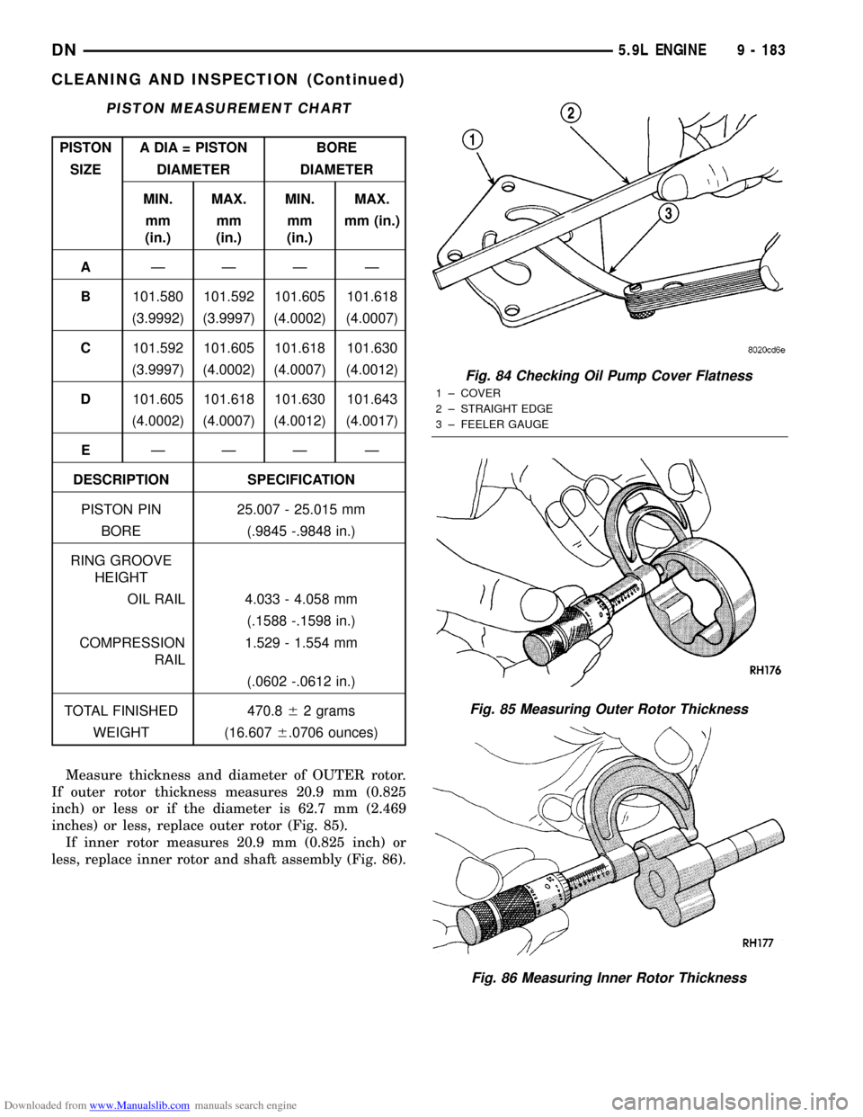
Downloaded from www.Manualslib.com manuals search engine Measure thickness and diameter of OUTER rotor.
If outer rotor thickness measures 20.9 mm (0.825
inch) or less or if the diameter is 62.7 mm (2.469
inches) or less, replace outer rotor (Fig. 85).
If inner rotor measures 20.9 mm (0.825 inch) or
less, replace inner rotor and shaft assembly (Fig. 86).
PISTON MEASUREMENT CHART
PISTON A DIA = PISTON BORE
SIZE DIAMETER DIAMETER
MIN. MAX. MIN. MAX.
mm
(in.)mm
(in.)mm
(in.)mm (in.)
AÐÐÐ Ð
B101.580 101.592 101.605 101.618
(3.9992) (3.9997) (4.0002) (4.0007)
C101.592 101.605 101.618 101.630
(3.9997) (4.0002) (4.0007) (4.0012)
D101.605 101.618 101.630 101.643
(4.0002) (4.0007) (4.0012) (4.0017)
EÐÐÐ Ð
DESCRIPTION SPECIFICATION
PISTON PIN 25.007 - 25.015 mm
BORE (.9845 -.9848 in.)
RING GROOVE
HEIGHT
OIL RAIL 4.033 - 4.058 mm
(.1588 -.1598 in.)
COMPRESSION
RAIL1.529 - 1.554 mm
(.0602 -.0612 in.)
TOTAL FINISHED 470.862 grams
WEIGHT (16.6076.0706 ounces)
Fig. 84 Checking Oil Pump Cover Flatness
1 ± COVER
2 ± STRAIGHT EDGE
3 ± FEELER GAUGE
Fig. 85 Measuring Outer Rotor Thickness
Fig. 86 Measuring Inner Rotor Thickness
DN5.9L ENGINE 9 - 183
CLEANING AND INSPECTION (Continued)
Page 189 of 193
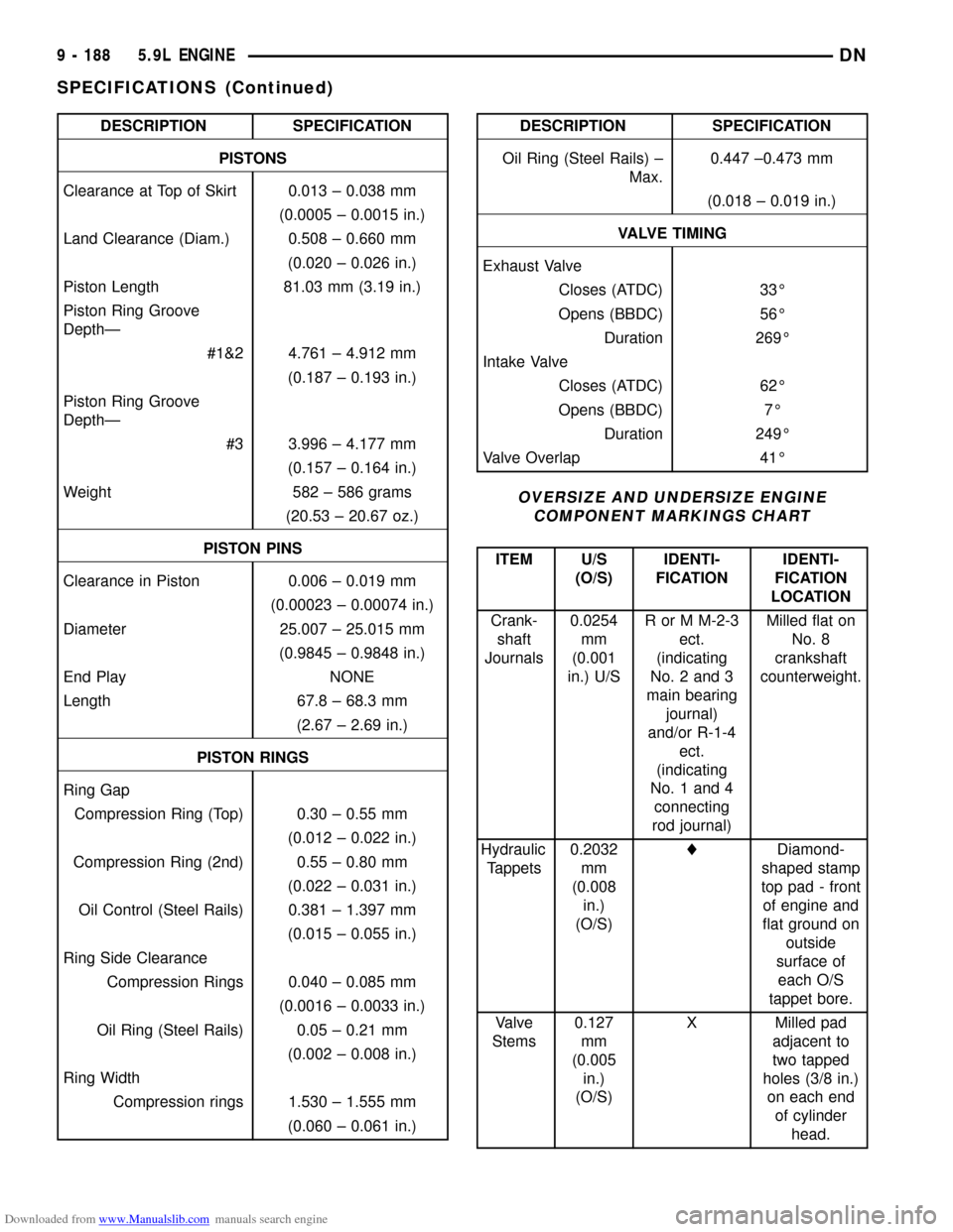
Downloaded from www.Manualslib.com manuals search engine DESCRIPTION SPECIFICATION
PISTONS
Clearance at Top of Skirt 0.013 ± 0.038 mm
(0.0005 ± 0.0015 in.)
Land Clearance (Diam.) 0.508 ± 0.660 mm
(0.020 ± 0.026 in.)
Piston Length 81.03 mm (3.19 in.)
Piston Ring Groove
DepthÐ
#1&2 4.761 ± 4.912 mm
(0.187 ± 0.193 in.)
Piston Ring Groove
DepthÐ
#3 3.996 ± 4.177 mm
(0.157 ± 0.164 in.)
Weight 582 ± 586 grams
(20.53 ± 20.67 oz.)
PISTON PINS
Clearance in Piston 0.006 ± 0.019 mm
(0.00023 ± 0.00074 in.)
Diameter 25.007 ± 25.015 mm
(0.9845 ± 0.9848 in.)
End Play NONE
Length 67.8 ± 68.3 mm
(2.67 ± 2.69 in.)
PISTON RINGS
Ring Gap
Compression Ring (Top) 0.30 ± 0.55 mm
(0.012 ± 0.022 in.)
Compression Ring (2nd) 0.55 ± 0.80 mm
(0.022 ± 0.031 in.)
Oil Control (Steel Rails) 0.381 ± 1.397 mm
(0.015 ± 0.055 in.)
Ring Side Clearance
Compression Rings 0.040 ± 0.085 mm
(0.0016 ± 0.0033 in.)
Oil Ring (Steel Rails) 0.05 ± 0.21 mm
(0.002 ± 0.008 in.)
Ring Width
Compression rings 1.530 ± 1.555 mm
(0.060 ± 0.061 in.)DESCRIPTION SPECIFICATION
Oil Ring (Steel Rails) ±
Max.0.447 ±0.473 mm
(0.018 ± 0.019 in.)
VALVE TIMING
Exhaust Valve
Closes (ATDC) 33É
Opens (BBDC) 56É
Duration 269É
Intake Valve
Closes (ATDC) 62É
Opens (BBDC) 7É
Duration 249É
Valve Overlap 41É
OVERSIZE AND UNDERSIZE ENGINE
COMPONENT MARKINGS CHART
ITEM U/S
(O/S)IDENTI-
FICATIONIDENTI-
FICATION
LOCATION
Crank-
shaft
Journals0.0254
mm
(0.001
in.) U/SR or M M-2-3
ect.
(indicating
No. 2 and 3
main bearing
journal)
and/or R-1-4
ect.
(indicating
No. 1 and 4
connecting
rod journal)Milled flat on
No. 8
crankshaft
counterweight.
Hydraulic
Tappets0.2032
mm
(0.008
in.)
(O/S)lDiamond-
shaped stamp
top pad - front
of engine and
flat ground on
outside
surface of
each O/S
tappet bore.
Valve
Stems0.127
mm
(0.005
in.)
(O/S)X Milled pad
adjacent to
two tapped
holes (3/8 in.)
on each end
of cylinder
head.
9 - 188 5.9L ENGINEDN
SPECIFICATIONS (Continued)