spark plugs replace DODGE DURANGO 2000 1.G Workshop Manual
[x] Cancel search | Manufacturer: DODGE, Model Year: 2000, Model line: DURANGO, Model: DODGE DURANGO 2000 1.GPages: 193, PDF Size: 5.65 MB
Page 9 of 193
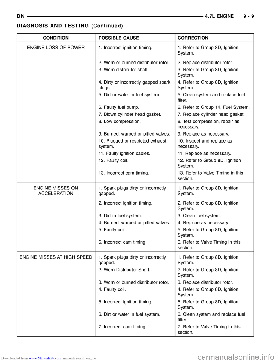
Downloaded from www.Manualslib.com manuals search engine CONDITION POSSIBLE CAUSE CORRECTION
ENGINE LOSS OF POWER 1. Incorrect ignition timing. 1. Refer to Group 8D, Ignition
System.
2. Worn or burned distributor rotor. 2. Replace distributor rotor.
3. Worn distributor shaft. 3. Refer to Group 8D, Ignition
System.
4. Dirty or incorrectly gapped spark
plugs.4. Refer to Group 8D, Ignition
System.
5. Dirt or water in fuel system. 5. Clean system and replace fuel
filter.
6. Faulty fuel pump. 6. Refer to Group 14, Fuel System.
7. Blown cylinder head gasket. 7. Replace cylinder head gasket.
8. Low compression. 8. Test compression, repair as
necessary.
9. Burned, warped or pitted valves. 9. Replace as necessary.
10. Plugged or restricted exhaust
system.10. Inspect and replace as
necessary.
11. Faulty ignition cables. 11. Replace as necessary.
12. Faulty coil. 12. Refer to Group 8D, Ignition
System.
13. Incorrect cam timing. 13. Refer to Valve Timing in this
section.
ENGINE MISSES ON
ACCELERATION1. Spark plugs dirty or incorrectly
gapped.1. Refer to Group 8D, Ignition
System.
2. Incorrect ignition timing. 2. Refer to Group 8D, Ignition
System.
3. Dirt in fuel system. 3. Clean fuel system.
4. Burned, warped or pitted valves. 4. Replcae as necessary.
5. Faulty coil. 5. Refer to Group 8D, Ignition
System.
6. Incorrect cam timing. 6. Refer to Valve Timing in this
section.
ENGINE MISSES AT HIGH SPEED 1. Spark plugs dirty or incorrectly
gapped.1. Refer to Group 8D, Ignition
System.
2. Worn Distributor Shaft. 2. Refer to Group 8D, Ignition
System.
3. Worn or burned distributor rotor. 3. Replace distributor rotor.
4. Faulty coil. 4. Refer to Group 8D, Ignition
System.
5. Incorrect ignition timing. 5. Refer to Group 8D, Ignition
System.
6. Dirt or water in fuel system. 6. Clean system and replace fuel
filter.
7. Incorrect cam timing. 7. Refer to Valve Timing in this
section.
DN4.7L ENGINE 9 - 9
DIAGNOSIS AND TESTING (Continued)
Page 11 of 193
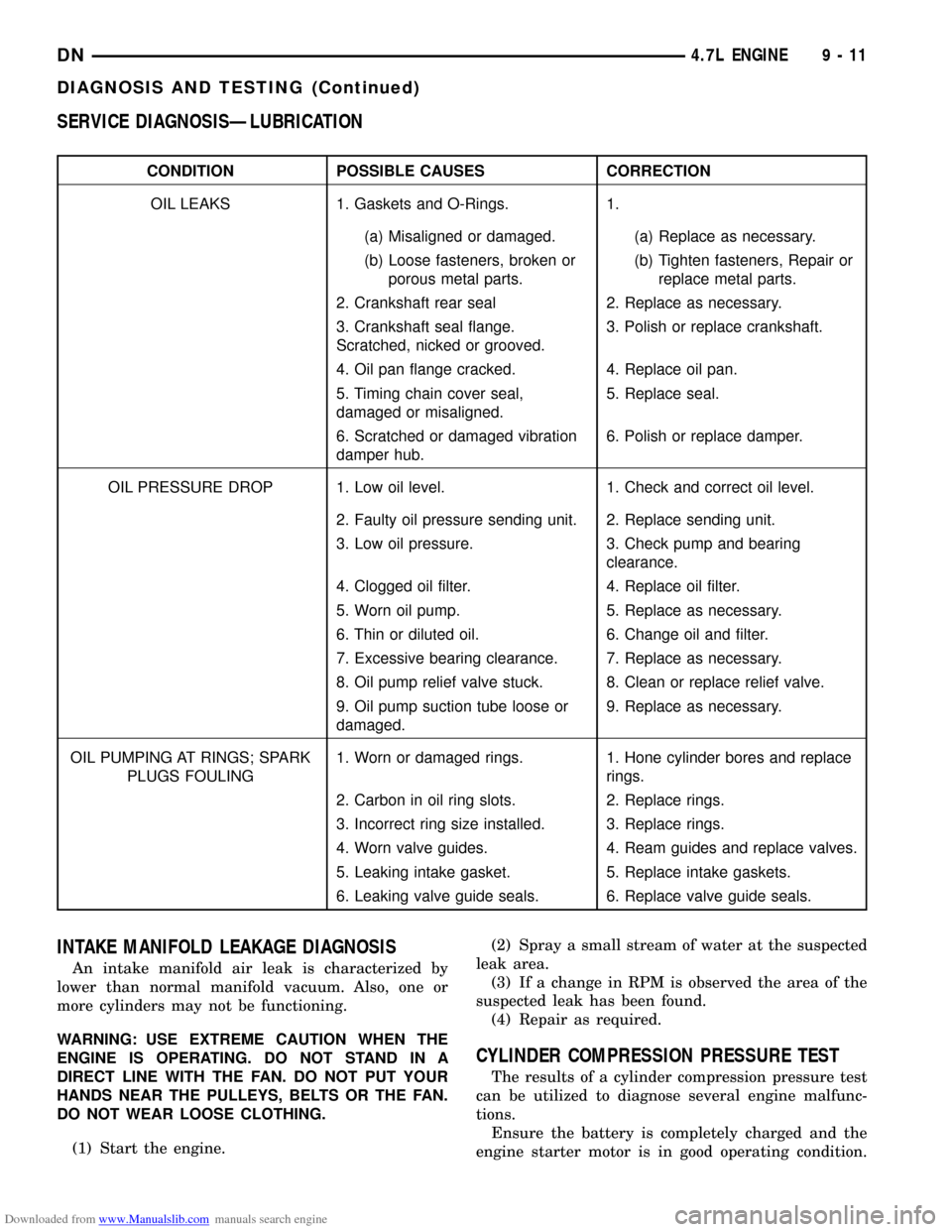
Downloaded from www.Manualslib.com manuals search engine SERVICE DIAGNOSISÐLUBRICATION
CONDITION POSSIBLE CAUSES CORRECTION
OIL LEAKS 1. Gaskets and O-Rings. 1.
(a) Misaligned or damaged. (a) Replace as necessary.
(b) Loose fasteners, broken or
porous metal parts.(b) Tighten fasteners, Repair or
replace metal parts.
2. Crankshaft rear seal 2. Replace as necessary.
3. Crankshaft seal flange.
Scratched, nicked or grooved.3. Polish or replace crankshaft.
4. Oil pan flange cracked. 4. Replace oil pan.
5. Timing chain cover seal,
damaged or misaligned.5. Replace seal.
6. Scratched or damaged vibration
damper hub.6. Polish or replace damper.
OIL PRESSURE DROP 1. Low oil level. 1. Check and correct oil level.
2. Faulty oil pressure sending unit. 2. Replace sending unit.
3. Low oil pressure. 3. Check pump and bearing
clearance.
4. Clogged oil filter. 4. Replace oil filter.
5. Worn oil pump. 5. Replace as necessary.
6. Thin or diluted oil. 6. Change oil and filter.
7. Excessive bearing clearance. 7. Replace as necessary.
8. Oil pump relief valve stuck. 8. Clean or replace relief valve.
9. Oil pump suction tube loose or
damaged.9. Replace as necessary.
OIL PUMPING AT RINGS; SPARK
PLUGS FOULING1. Worn or damaged rings. 1. Hone cylinder bores and replace
rings.
2. Carbon in oil ring slots. 2. Replace rings.
3. Incorrect ring size installed. 3. Replace rings.
4. Worn valve guides. 4. Ream guides and replace valves.
5. Leaking intake gasket. 5. Replace intake gaskets.
6. Leaking valve guide seals. 6. Replace valve guide seals.
INTAKE MANIFOLD LEAKAGE DIAGNOSIS
An intake manifold air leak is characterized by
lower than normal manifold vacuum. Also, one or
more cylinders may not be functioning.
WARNING: USE EXTREME CAUTION WHEN THE
ENGINE IS OPERATING. DO NOT STAND IN A
DIRECT LINE WITH THE FAN. DO NOT PUT YOUR
HANDS NEAR THE PULLEYS, BELTS OR THE FAN.
DO NOT WEAR LOOSE CLOTHING.
(1) Start the engine.(2) Spray a small stream of water at the suspected
leak area.
(3) If a change in RPM is observed the area of the
suspected leak has been found.
(4) Repair as required.
CYLINDER COMPRESSION PRESSURE TEST
The results of a cylinder compression pressure test
can be utilized to diagnose several engine malfunc-
tions.
Ensure the battery is completely charged and the
engine starter motor is in good operating condition.
DN4.7L ENGINE 9 - 11
DIAGNOSIS AND TESTING (Continued)
Page 19 of 193

Downloaded from www.Manualslib.com manuals search engine (6) Identify the fluid in the cylinders (i.e. coolant,
fuel, oil, etc.).
(7) Make sure all fluid has been removed from the
cylinders.
(8) Repair engine or components as necessary to
prevent this problem from occurring again.
(9) Squirt engine oil into the cylinders to lubricate
the walls. This will prevent damage on restart.
(10) Install new spark plugs.
(11) Drain engine oil. Remove and discard the oil
filter.
(12) Install the drain plug. Tighten the plug to 34
N´m (25 ft. lbs.) torque.
(13) Install a new oil filter.
(14) Fill engine crankcase with the specified
amount and grade of oil.
(15) Connect the negative cable to the battery.
(16) Start the engine and check for any leaks.
VALVE SERVICE
REFACING
NOTE: Valve seats that are worn or burned can be
reworked, provided that correct angle and seat
width are maintained. Otherwise the cylinder head
must be replaced.
NOTE: When refacing valves and valve seats, it is
important that the correct size valve guide pilot be
used for reseating stones. A true and complete sur-
face must be obtained.
(1) Using a suitable dial indicator measure the
center of the valve seat Total run out must not
exceed 0.051 mm (0.002 in).
(2) Apply a small amount of Prussian blue to the
valve seat, insert the valve into the cylinder head,
while applying light pressure on the valve rotate the
valve. Remove the valve and examine the valve face.
If the blue is transferred below the top edge of the
valve face, lower the valve seat using a 15 degree
stone. If the blue is transferred to the bottom edge of
the valve face, raise the valve seat using a 65 degree
stone.
(3) When the seat is properly positioned the width
of the intake seat must be 1.75 ± 2.36 mm (0.0689 ±
0.0928 in.) and the exhaust seat must be 1.71 ± 2.32
mm (0.0673 ± 0.0911 in.).
(4) Check the valve spring installed height after
refacing the valve and seat. The installed height for
both intake and exhaust valve springs must not
exceed 41.44 mm (1.6315 in.).
(5) The valve seat and valve face must maintain a
face angle of 44.5 ± 45 degrees angle.
ENGINE TIMINGÐVERIFICATION
CAUTION: The 4.7L is a non free-wheeling design
engine. Therefore, correct engine timing is critical.
NOTE: Components referred to as left hand or right
hand are as viewed from the drivers position inside
the vehicle.
NOTE: The blue link plates on the chains and the
dots on the camshaft drive sprockets may not line
up during the timing verification procedure. The
blue link plates are lined up with the sprocket dots
only when re-timing the complete timing drive.
Once the timing drive is rotated blue link-to-dot
alignment is no longer valid.
Engine base timing can be verified by the following
procedure:
(1) Remove the cylinder head covers. Refer to the
procedure in this section.
(2) Using a mirror, locate the TDC arrow on the
front cover (Fig. 11). Rotate the crankshaft until the
mark on the crankshaft damper is aligned with the
TDC arrow on the front cover. The engine is now at
TDC.
Fig. 10 Valve Assembly Configuration
1 ± VALVE LOCKS (3±BEAD)
2 ± RETAINER
3 ± VALVE STEM OIL SEAL
4 ± INTAKE VALVE
5 ± EXHAUST VALVE
6 ± VALVE SPRING
DN4.7L ENGINE 9 - 19
SERVICE PROCEDURES (Continued)
Page 92 of 193

Downloaded from www.Manualslib.com manuals search engine Scrape or wire brush all gasket surfaces to remove
all loose material. Inspect stamped parts to ensure
gasket rails are flat. Flatten rails with a hammer on
a flat plate, if required. Gasket surfaces must be free
of oil and dirt. Make sure the old gasket material is
removed from blind attaching holes.
GASKET APPLICATION
Assembling parts using a form-in-place gasket
requires care.
Mopar Silicone Rubber Adhesive Sealant should be
applied in a continuous bead approximately 3 mm
(0.12 inch) in diameter. All mounting holes must be
circled. For corner sealing,a3or6mm(1/8 or 1/4
inch) drop is placed in the center of the gasket con-
tact area. Uncured sealant may be removed with a
shop towel. Components should be torqued in place
while the sealant is still wet to the touch (within 10
minutes). The use of a locating dowel is recom-
mended during assembly to prevent smearing the
material off location.
Mopar Gasket Maker should be applied sparingly
to one gasket surface. The sealant diameter should
be 1.00 mm (0.04 inch) or less. Be certain the mate-
rial surrounds each mounting hole. Excess material
can easily be wiped off. Components should be
torqued in place within 15 minutes. The use of a
locating dowel is recommended during assembly to
prevent smearing the material off location.
ENGINE PERFORMANCE
It is important that the vehicle is operating to its
optimum performance level to maintain fuel economy
and the lowest emission levels. If vehicle is not oper-
ating to these standards, refer to Engine Diagnosis
outlined in this section. The following procedures can
assist in achieving the proper engine diagnosis.
(1) Test cranking amperage draw. Refer to Electri-
cal Group 8B, Cold Cranking Test.
(2) Check intake manifold bolt torque.
(3) Perform cylinder compression test. Refer to
Cylinder Compression Pressure Test in the Engine
Diagnosis area of this section.
(4) Clean or replace spark plugs as necessary and
adjust gap as specified in Electrical Group 8D.
Tighten to specifications.
(5) Test resistance of spark plug cables. Refer to
Electrical Group 8D, Spark Plug Cables.
(6) Inspect the primary wires. Test coil output volt-
age and primary resistance. Replace parts as neces-
sary. Refer to Electrical Group 8D, for specifications.
(7) Test fuel pump for pressure. Refer to Group 14,
Fuel System Specifications.
(8) The air filter elements should be replaced as
specified in Lubrication and Maintenance, Group 0.(9) Inspect crankcase ventilation system as out
lined in Group 0, Lubrication and Maintenance. For
emission controls see Group 25, Emission Controls
for service procedures.
(10) Road test vehicle as a final test.
ENGINE OIL
WARNING: NEW OR USED ENGINE OIL CAN BE
IRRITATING TO THE SKIN. AVOID PROLONGED OR
REPEATED SKIN CONTACT WITH ENGINE OIL.
CONTAMINANTS IN USED ENGINE OIL, CAUSED BY
INTERNAL COMBUSTION, CAN BE HAZARDOUS TO
YOUR HEALTH. THOROUGHLY WASH EXPOSED
SKIN WITH SOAP AND WATER. DO NOT WASH
SKIN WITH GASOLINE, DIESEL FUEL, THINNER, OR
SOLVENTS, HEALTH PROBLEMS CAN RESULT. DO
NOT POLLUTE, DISPOSE OF USED ENGINE OIL
PROPERLY.
ENGINE OIL SPECIFICATION
CAUTION: Do not use non-detergent or straight
mineral oil when adding or changing crankcase
lubricant. Engine failure can result.
API SERVICE GRADE CERTIFIED
In gasoline engines, use an engine oil that is API
Service Grade Certified (Fig. 11). Standard engine oil
identification notations have been adopted to aid in
the proper selection of engine oil. The identifying
notations are located on the label of engine oil plastic
bottles and the top of engine oil cans. MOPAR only
provides engine oil that conforms to this certification.
SAE VISCOSITY
An SAE viscosity grade is used to specify the vis-
cosity of engine oil. SAE 10W-30 specifies a multiple
viscosity engine oil. These are specified with a dual
SAE viscosity grade which indicates the cold-to-hot
temperature viscosity range. When choosing an
engine oil, consider the range of temperatures the
vehicle will be operated in before the next oil change.
Select an engine oil that is best suited to your area's
Fig. 11 Engine Oil Container Standard Notations
9 - 92 5.2L ENGINEDN
SERVICE PROCEDURES (Continued)
Page 95 of 193

Downloaded from www.Manualslib.com manuals search engine (4) A controlled hone motor speed between 200 and
300 RPM is necessary to obtain the proper cross-
hatch angle. The number of up and down strokes per
minute can be regulated to get the desired 50É to 60É
angle. Faster up and down strokes increase the cross-
hatch angle.
(5) After honing, it is necessary that the block be
cleaned to remove all traces of abrasive. Use a brush
to wash parts with a solution of hot water and deter-
gent. Dry parts thoroughly. Use a clean, white, lint-
free cloth to check that the bore is clean. Oil the
bores after cleaning to prevent rusting.
HYDROSTATIC LOCK
When an engine is suspected of hydrostatic lock
(regardless of what caused the problem), follow the
steps below.
(1) Perform the Fuel Pressure Release Procedure
(refer to Group 14, Fuel System).
(2) Disconnect the battery negative cable.
(3) Inspect air cleaner, induction system and
intake manifold to ensure system is dry and clear of
foreign material.
(4) Place a shop towel around the spark plugs to
catch any fluid that may possibly be under pressure
in the cylinder head. Remove the plugs from the
engine.
CAUTION: DO NOT use the starter motor to rotate
the crankshaft. Severe damage could occur.
(5) With all spark plugs removed, rotate the crank-
shaft using a breaker bar and socket.
(6) Identify the fluid in the cylinders (i.e. coolant,
fuel, oil, etc.).
(7) Make sure all fluid has been removed from the
cylinders.
(8) Repair engine or components as necessary to
prevent this problem from occurring again.
(9) Squirt engine oil into the cylinders to lubricate
the walls. This will prevent damage on restart.
(10) Install new spark plugs.
(11) Drain engine oil. Remove and discard the oil
filter.
(12) Install the drain plug. Tighten the plug to 34
N´m (25 ft. lbs.) torque.
(13) Install a new oil filter.
(14) Fill engine crankcase with the specified
amount and grade of oil.
(15) Connect the negative cable to the battery.
(16) Start the engine and check for any leaks.
VALVE TIMING
(1) Turn crankshaft until the No.6 exhaust valve is
closing and No.6 intake valve is opening.(2) Insert a 6.350 mm (1/4 inch) spacer between
rocker arm pad and stem tip of No.1 intake valve.
Allow spring load to bleed tappet down giving in
effect a solid tappet.
(3) Install a dial indicator so plunger contacts
valve spring retainer as nearly perpendicular as pos-
sible. Zero the indicator.
(4) Rotate the crankshaft clockwise (normal run-
ning direction) until the valve has lifted 0.863 mm
(0.034 inch). The timing of the crankshaft should
now read from 10É before top dead center to 2É after
top dead center. Remove spacer.
CAUTION: DO NOT turn crankshaft any further
clockwise as valve spring might bottom and result
in serious damage.
If reading is not within specified limits:
²Check sprocket index marks.
²Inspect timing chain for wear.
²Check accuracy of DC mark on timing indicator.
VALVE SERVICE
VALVE CLEANING
Clean valves thoroughly. Discard burned, warped
and cracked valves.
Remove carbon and varnish deposits from inside of
valve guides with a reliable guide cleaner.
VALVE INSPECTION
Measure valve stems for wear. If wear exceeds
0.051 mm (0.002 inch), replace the valve.
VALVE GUIDES
Measure valve stem guide clearance as follows:
(1) Install Valve Guide Sleeve Tool C-3973 over
valve stem and install valve (Fig. 17). The special
sleeve places the valve at the correct height for
checking with a dial indicator.
Fig. 17 Positioning Valve with Tool C-3973
1 ± VALVE
2 ± SPACER TOOL
DN5.2L ENGINE 9 - 95
SERVICE PROCEDURES (Continued)
Page 107 of 193

Downloaded from www.Manualslib.com manuals search engine (2) Position the cylinder head cover onto the gas-
ket. Tighten the bolts to 11 N´m (95 in. lbs.) torque.
(3) Install closed crankcase ventilation system and
evaporation control system.
(4) Install the air inlet hose.
(5) Connect the negative cable to the battery.
ROCKER ARMS AND PUSH RODS
REMOVAL
(1) Remove cylinder head cover and gasket. Refer
to Cylinder Head Cover in this section for correct
procedure.
(2) Remove the rocker arm bolts and pivots (Fig.
44). Place them on a bench in the same order as
removed.
(3) Remove the push rods and place them on a
bench in the same order as removed.
INSTALLATION
(1) Rotate the crankshaft until the ªV8º mark lines
up with the TDC mark on the timing chain case
cover. This mark is located 147É ATDC from the No.1
firing position.
(2) Install the push rods in the same order as
removed.
(3) Install rocker arm and pivot assemblies in the
same order as removed. Tighten the rocker arm bolts
to 28 N´m (21 ft. lbs.) torque.
CAUTION: DO NOT rotate or crank the engine dur-
ing or immediately after rocker arm installation.
Allow the hydraulic roller tappets adequate time to
bleed down (about 5 minutes).
(4) Install cylinder head cover.
VALVE SPRING AND STEM SEAL
REPLACEMENT-IN VEHICLE
(1) Remove the air cleaner.
(2) Remove cylinder head covers and spark plugs.(3) Remove coil wire from distributor and secure to
good ground to prevent engine from starting.
(4) Using suitable socket and flex handle at crank-
shaft retaining bolt, turn engine so the No.1 piston is
at TDC on the compression stroke.
(5) Remove rocker arms.
(6) With air hose attached to an adapter installed
in No.1 spark plug hole, apply 620-689 kPa (90-100
psi) air pressure.
(7) Using Valve Spring Compressor Tool
MD-998772A with adaptor 6716A, compress valve
spring and remove retainer valve locks and valve
spring.
(8) Install seals on the exhaust valve stem and
position down against valve guides.
(9) The intake valve stem seals should be pushed
firmly and squarely over the valve guide using the
valve stem as a guide. DO NOT force seal against top
of guide. When installing the valve retainer locks,
compress the spring only enough to install the locks.
(10) Follow the same procedure on the remaining 7
cylinders using the firing sequence 1-8-4-3-6-5-7-2.
Make sure piston in cylinder is at TDC on the valve
spring that is being removed.
(11) Remove adapter from the No.1 spark plug
hole and install spark plugs.
(12) Install rocker arms.
(13) Install covers and coil wire to distributor.
(14) Install air cleaner.
(15) Road test vehicle.
CYLINDER HEAD
REMOVAL
(1) Disconnect the battery negative cable.
(2) Drain cooling system Refer to COOLING SYS-
TEM.
(3) Remove the intake manifold-to-generator
bracket support rod. Remove the generator.
(4) Remove closed crankcase ventilation system.
(5) Disconnect the evaporation control system.
(6) Remove the air cleaner assembly and air inlet
hose.
(7) Perform fuel system pressure release proce-
dure. Refer to FUEL SYSTEM.
(8) Disconnect the fuel supply line.
(9) Disconnect accelerator linkage and if so
equipped, the speed control and transmission kick-
down cables.
(10) Remove distributor cap and wires.
(11) Disconnect the coil wires.
(12) Disconnect heat indicator sending unit wire.
(13) Disconnect heater hoses and bypass hose.
(14) Remove cylinder head covers and gaskets.
Fig. 44 Rocker Arms
1 ± ROCKER ARMS
2 ± CYLINDER HEAD
DN5.2L ENGINE 9 - 107
REMOVAL AND INSTALLATION (Continued)
Page 108 of 193

Downloaded from www.Manualslib.com manuals search engine (15) Remove intake manifold and throttle body as
an assembly. Discard the flange side gaskets and the
front and rear cross-over gaskets.
(16) Remove exhaust manifolds.
(17) Remove rocker arm assemblies and push rods.
Identify to ensure installation in original locations.
(18) Remove the head bolts from each cylinder
head and remove cylinder heads. Discard the cylin-
der head gasket.
(19) Remove spark plugs.
INSTALLATION
(1) Position the new cylinder head gaskets onto
the cylinder block.
(2) Position the cylinder heads onto head gaskets
and cylinder block.
(3) Starting at top center, tighten all cylinder head
bolts, in sequence, to 68 N´m (50 ft. lbs.) torque (Fig.
45). Repeat procedure, tighten all cylinder head bolts
to 143 N´m (105 ft. lbs.) torque. Repeat procedure to
confirm that all bolts are at 143 N´m (105 ft. lbs.)
torque.
CAUTION: When tightening the rocker arm bolts,
make sure the piston in that cylinder is NOT at
TDC. Contact between the valves and piston could
occur.
(4) Install push rods and rocker arm assemblies in
their original position. Tighten the bolts to 28 N´m
(21 ft. lbs.) torque.
(5) Install the intake manifold and throttle body
assembly.
(6) Install exhaust manifolds. Tighten the bolts
and nuts to 34 N´m (25 ft. lbs.) torque.
(7) Adjust spark plugs to specifications. Refer to
IGNITION SYSTEM. Install the plugs and tighten to
41 N´m (30 ft. lbs.) torque.
(8) Install coil wires.
(9) Connect heat indicator sending unit wire.(10) Connect the heater hoses and bypass hose.
(11) Install distributor cap and wires.
(12) Connect the accelerator linkage and if so
equipped, the speed control and transmission kick-
down cables.
(13) Install the fuel supply line.
(14) Install the generator and drive belt. Tighten
generator mounting bolt to 41 N´m (30 ft. lbs.)
torque.
(15) Install the intake manifold-to-generator
bracket support rod. Tighten the bolts.
(16) Place the cylinder head cover gaskets in posi-
tion and install cylinder head covers. Tighten the
bolts to 11 N´m (95 in. lbs.) torque.
(17) Install closed crankcase ventilation system.
(18) Connect the evaporation control system.
(19) Install the air cleaner assembly and air inlet
hose.
(20) Install the heat shields. Tighten the bolts to
41 N´m (30 ft. lbs.) torque.
(21) Fill cooling system.
(22) Connect the battery negative cable.
VALVES AND VALVE SPRINGS
REMOVAL
(1) Remove the cylinder head. Refer to Cylinder
Head in this section for correct procedure.
(2) Compress valve springs using Valve Spring
Compressor Tool MD- 998772A and adapter 6716A.
(3) Remove valve retaining locks, valve spring
retainers, valve stem seals and valve springs.
(4) Before removing valves, remove any burrs from
valve stem lock grooves to prevent damage to the
valve guides. Identify valves to ensure installation in
original location.
INSTALLATION
(1) Clean valves thoroughly. Discard burned,
warped and cracked valves.
(2) Remove carbon and varnish deposits from
inside of valve guides with a reliable guide cleaner.
(3) Measure valve stems for wear. If wear exceeds
0.051 mm (0.002 inch), replace the valve.
(4) Coat valve stems with lubrication oil and insert
them in cylinder head.
(5) If valves or seats are reground, check valve
stem height. If valve is too long, replace cylinder
head.
(6) Install new seals on all valve guides. Install
valve springs and valve retainers.
(7) Compress valve springs with Valve Spring
Compressor Tool MD-998772A and adapter 6716A,
install locks and release tool. If valves and/or seats
are ground, measure the installed height of springs.
Make sure the measurement is taken from bottom ofFig. 45 Cylinder Head Bolt Tightening Sequence
9 - 108 5.2L ENGINEDN
REMOVAL AND INSTALLATION (Continued)
Page 143 of 193
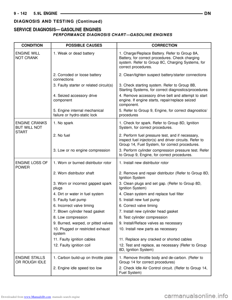
Downloaded from www.Manualslib.com manuals search engine SERVICE DIAGNOSISÐGASOLINE ENGINES
PERFORMANCE DIAGNOSIS CHARTÐGASOLINE ENGINES
CONDITION POSSIBLE CAUSES CORRECTION
ENGINE WILL
NOT CRANK1. Weak or dead battery 1. Charge/Replace Battery. Refer to Group 8A,
Battery, for correct procedures. Check charging
system. Refer to Group 8C, Charging Systems, for
correct procedures.
2. Corroded or loose battery
connections2. Clean/tighten suspect battery/starter connections
3. Faulty starter or related circuit(s) 3. Check starting system. Refer to Group 8B,
Starting Systems, for correct diagnostics/procedures
4. Seized accessory drive
component4. Remove accessory drive belt and attempt to start
engine. If engine starts, repair/replace seized
component.
5. Engine internal mechanical
failure or hydro-static lock5. Refer to Group 9, Engine, for correct diagnostics/
procedures
ENGINE CRANKS
BUT WILL NOT
START1. No spark 1. Check for spark. Refer to Group 8D, Ignition
System, for correct procedures.
2. No fuel 2. Perform fuel pressure test, and if necessary,
inspect fuel injector(s) and driver circuits. Refer to
Group 14, Fuel System, for correct procedures.
3. Low or no engine compression 3. Perform cylinder compression pressure test. Refer
to Group 9, Engine, for correct procedures.
ENGINE LOSS OF
POWER1. Worn or burned distributor rotor 1. Install new distributor rotor
2. Worn distributor shaft 2. Remove and repair distributor (Refer to Group 8D,
Ignition System
3. Worn or incorrect gapped spark
plugs3. Clean plugs and set gap. (Refer to Group 8D,
Ignition System)
4. Dirt or water in fuel system 4. Clean system and replace fuel filter
5. Faulty fuel pump 5. Install new fuel pump
6. Incorrect valve timing 6. Correct valve timing
7. Blown cylinder head gasket 7. Install new cylinder head gasket
8. Low compression 8. Test cylinder compression
9. Burned, warped, or pitted valves 9. Install/Reface valves as necessary
10. Plugged or restricted exhaust
system10. Install new parts as necessary
11. Faulty ignition cables 11. Replace any cracked or shorted cables
12. Faulty ignition coil 12. Test and replace, as necessary (Refer to Group
8D, Ignition System)
ENGINE STALLS
OR ROUGH IDLE1. Carbon build-up on throttle plate 1. Remove throttle body and de-carbon. (Refer to
Group 14 for correct procedures)
2. Engine idle speed too low 2. Check Idle Air Control circuit. (Refer to Group 14,
Fuel System)
9 - 142 5.9L ENGINEDN
DIAGNOSIS AND TESTING (Continued)
Page 144 of 193
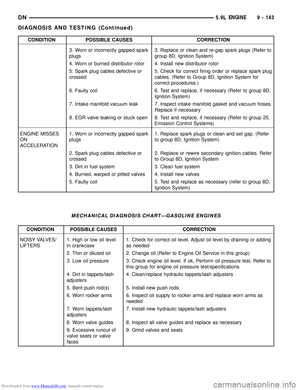
Downloaded from www.Manualslib.com manuals search engine CONDITION POSSIBLE CAUSES CORRECTION
3. Worn or incorrectly gapped spark
plugs3. Replace or clean and re-gap spark plugs (Refer to
group 8D, Ignition System)
4. Worn or burned distributor rotor 4. Install new distributor rotor
5. Spark plug cables defective or
crossed5. Check for correct firing order or replace spark plug
cables. (Refer to Group 8D, Ignition System for
correct procedures.)
6. Faulty coil 6. Test and replace, if necessary (Refer to group 8D,
Ignition System)
7. Intake manifold vacuum leak 7. Inspect intake manifold gasket and vacuum hoses.
Replace if necessary
8. EGR valve leaking or stuck open 8. Test and replace, if necessary (Refer to group 25,
Emission Control Systems)
ENGINE MISSES
ON
ACCELERATION1. Worn or incorrectly gapped spark
plugs1. Replace spark plugs or clean and set gap. (Refer
to group 8D, Ignition System)
2. Spark plug cables defective or
crossed2. Replace or rewire secondary ignition cables. Refer
to Group 8D, Ignition System
3. Dirt in fuel system 3. Clean fuel system
4. Burned, warped or pitted valves 4. Install new valves
5. Faulty coil 5. Test and replace as necessary (refer to group 8D,
Ignition System)
MECHANICAL DIAGNOSIS CHARTÐGASOLINE ENGINES
CONDITION POSSIBLE CAUSES CORRECTION
NOISY VALVES/
LIFTERS1. High or low oil level
in crankcase1. Check for correct oil level. Adjust oil level by draining or adding
as needed
2. Thin or diluted oil 2. Change oil (Refer to Engine Oil Service in this group)
3. Low oil pressure 3. Check engine oil level. If ok, Perform oil pressure test. Refer to
this group for engine oil pressure test/specifications
4. Dirt in tappets/lash
adjusters4. Clean/replace hydraulic tappets/lash adjusters
5. Bent push rod(s) 5. Install new push rods
6. Worn rocker arms 6. Inspect oil supply to rocker arms and replace worn arms as
needed
7. Worn tappets/lash
adjusters7. Install new hydraulic tappets/lash adjusters
8. Worn valve guides 8. Inspect all valve guides and replace as necessary
9. Excessive runout of
valve seats or valve
faces9. Grind valves and seats
DN5.9L ENGINE 9 - 143
DIAGNOSIS AND TESTING (Continued)
Page 146 of 193
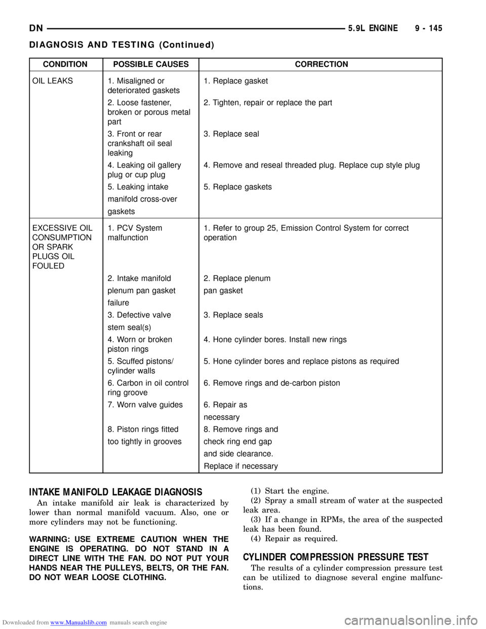
Downloaded from www.Manualslib.com manuals search engine CONDITION POSSIBLE CAUSES CORRECTION
OIL LEAKS 1. Misaligned or
deteriorated gaskets1. Replace gasket
2. Loose fastener,
broken or porous metal
part2. Tighten, repair or replace the part
3. Front or rear
crankshaft oil seal
leaking3. Replace seal
4. Leaking oil gallery
plug or cup plug4. Remove and reseal threaded plug. Replace cup style plug
5. Leaking intake 5. Replace gaskets
manifold cross-over
gaskets
EXCESSIVE OIL
CONSUMPTION
OR SPARK
PLUGS OIL
FOULED1. PCV System
malfunction1. Refer to group 25, Emission Control System for correct
operation
2. Intake manifold 2. Replace plenum
plenum pan gasket pan gasket
failure
3. Defective valve 3. Replace seals
stem seal(s)
4. Worn or broken
piston rings4. Hone cylinder bores. Install new rings
5. Scuffed pistons/
cylinder walls5. Hone cylinder bores and replace pistons as required
6. Carbon in oil control
ring groove6. Remove rings and de-carbon piston
7. Worn valve guides 6. Repair as
necessary
8. Piston rings fitted 8. Remove rings and
too tightly in grooves check ring end gap
and side clearance.
Replace if necessary
INTAKE MANIFOLD LEAKAGE DIAGNOSIS
An intake manifold air leak is characterized by
lower than normal manifold vacuum. Also, one or
more cylinders may not be functioning.
WARNING: USE EXTREME CAUTION WHEN THE
ENGINE IS OPERATING. DO NOT STAND IN A
DIRECT LINE WITH THE FAN. DO NOT PUT YOUR
HANDS NEAR THE PULLEYS, BELTS, OR THE FAN.
DO NOT WEAR LOOSE CLOTHING.(1) Start the engine.
(2) Spray a small stream of water at the suspected
leak area.
(3) If a change in RPMs, the area of the suspected
leak has been found.
(4) Repair as required.
CYLINDER COMPRESSION PRESSURE TEST
The results of a cylinder compression pressure test
can be utilized to diagnose several engine malfunc-
tions.
DN5.9L ENGINE 9 - 145
DIAGNOSIS AND TESTING (Continued)