DODGE DURANGO 2006 2.G Owners Manual
DURANGO 2006 2.G
DODGE
DODGE
https://www.carmanualsonline.info/img/12/5605/w960_5605-0.png
DODGE DURANGO 2006 2.G Owners Manual
Trending: fuel additives, ground clearance, CD player, adding oil, clutch, change wheel, fuel reserve
Page 371 of 440
FUSE BLOCK
CAUTION!
When replacing a blown fuse, it is important to use
only a fuse having the correct amperage rating. The
use of a fuse with a rating other than indicated may
result in a dangerous electrical system overload. If a
properly rated fuse continues to blow, it suggests a
problem in the circuit that must be corrected.
NOTE:If you are leaving your vehicle dormant for
longer than 21 days you may want to take steps to protect
your battery. You may do this by disconnecting the
battery or by disconnecting the two ignition-off draw
(I.O.D.) fuses located in the Auxiliary Power Distribution
Center (PDC) located in the engine compartment. The
I.O.D. cavities include a snap-in retainer that allows thefuse to be disconnected, without removing it from the
fuse block. Pressing the I.O.D. fuse back into the cavity
reconnects it.
Interior Fuses
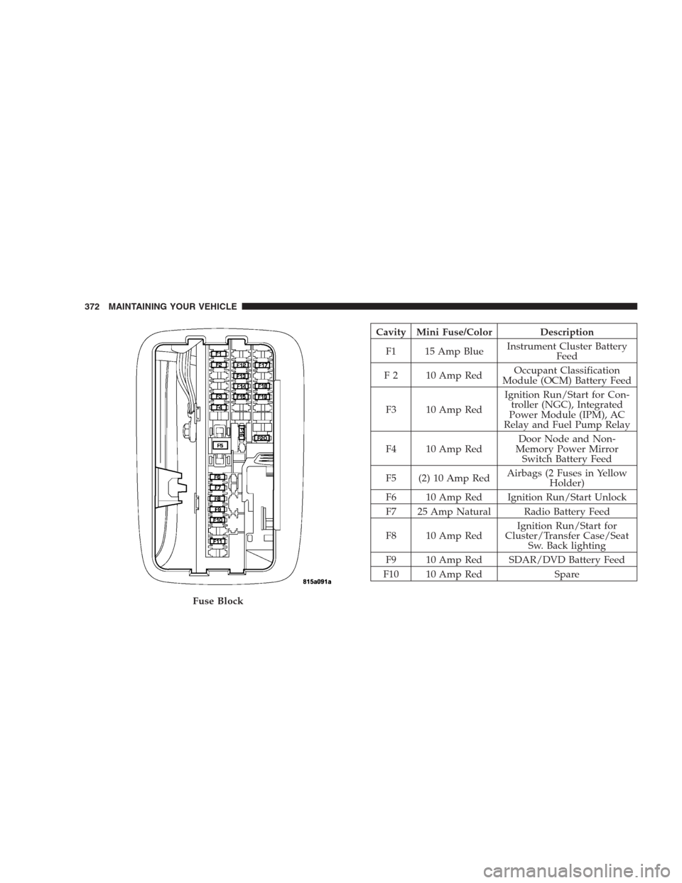
The fuse block contains blade-type mini-fuses, relays, and
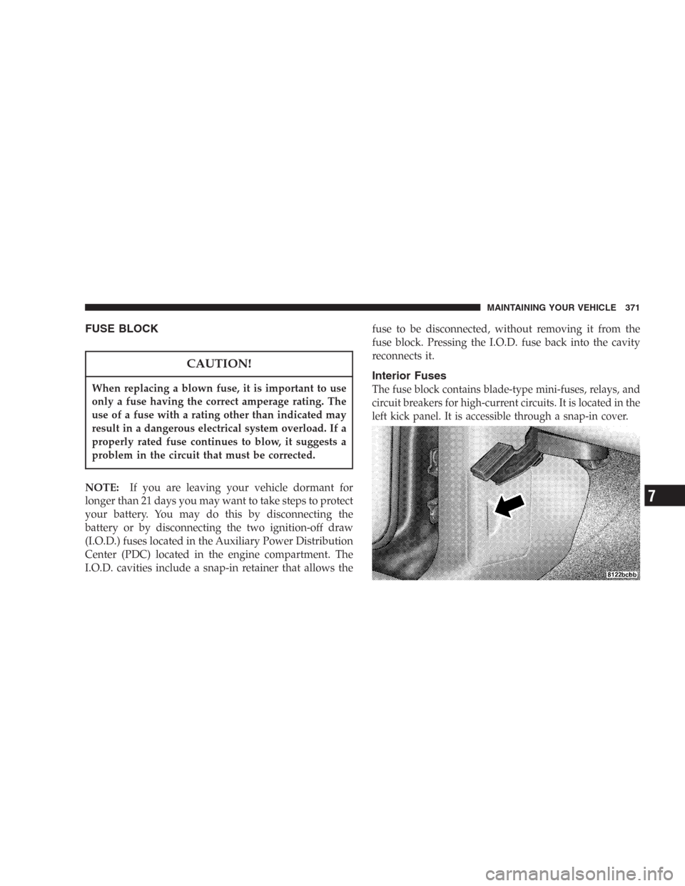
circuit breakers for high-current circuits. It is located in the
left kick panel. It is accessible through a snap-in cover.
MAINTAINING YOUR VEHICLE 371
7
Page 372 of 440
Cavity Mini Fuse/Color Description
F1 15 Amp BlueInstrument Cluster Battery
Feed
F 2 10 Amp RedOccupant Classification
Module (OCM) Battery Feed
F3 10 Amp RedIgnition Run/Start for Con-
troller (NGC), Integrated
Power Module (IPM), AC
Relay and Fuel Pump Relay
F4 10 Amp RedDoor Node and Non-
Memory Power Mirror
Switch Battery Feed
F5 (2) 10 Amp RedAirbags (2 Fuses in Yellow
Holder)
F6 10 Amp Red Ignition Run/Start Unlock
F7 25 Amp Natural Radio Battery Feed
F8 10 Amp RedIgnition Run/Start for
Cluster/Transfer Case/Seat
Sw. Back lighting
F9 10 Amp Red SDAR/DVD Battery Feed
F10 10 Amp Red Spare
Fuse Block
372 MAINTAINING YOUR VEHICLE
Page 373 of 440
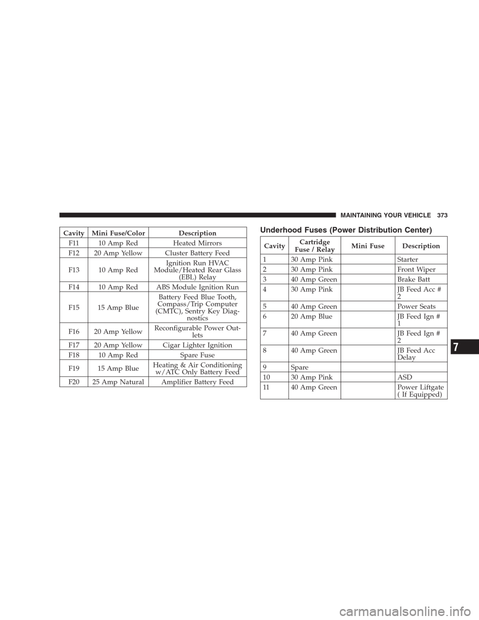
Cavity Mini Fuse/Color Description
F11 10 Amp Red Heated Mirrors
F12 20 Amp Yellow Cluster Battery Feed
F13 10 Amp RedIgnition Run HVAC
Module/Heated Rear Glass
(EBL) Relay
F14 10 Amp Red ABS Module Ignition Run
F15 15 Amp BlueBattery Feed Blue Tooth,
Compass/Trip Computer
(CMTC), Sentry Key Diag-
nostics
F16 20 Amp YellowReconfigurable Power Out-
lets
F17 20 Amp Yellow Cigar Lighter Ignition
F18 10 Amp Red Spare Fuse
F19 15 Amp BlueHeating & Air Conditioning
w/ATC Only Battery Feed
F20 25 Amp Natural Amplifier Battery FeedUnderhood Fuses (Power Distribution Center)
CavityCartridge
Fuse / RelayMini Fuse Description
1 30 Amp Pink Starter
2 30 Amp Pink Front Wiper
3 40 Amp Green Brake Batt
4 30 Amp Pink JB Feed Acc #
2
5 40 Amp Green Power Seats
6 20 Amp Blue JB Feed Ign #
1
7 40 Amp Green JB Feed Ign #
2
8 40 Amp Green JB Feed Acc
Delay
9 Spare
10 30 Amp Pink ASD
11 40 Amp Green Power Liftgate
( If Equipped)
MAINTAINING YOUR VEHICLE 373
7
Page 374 of 440
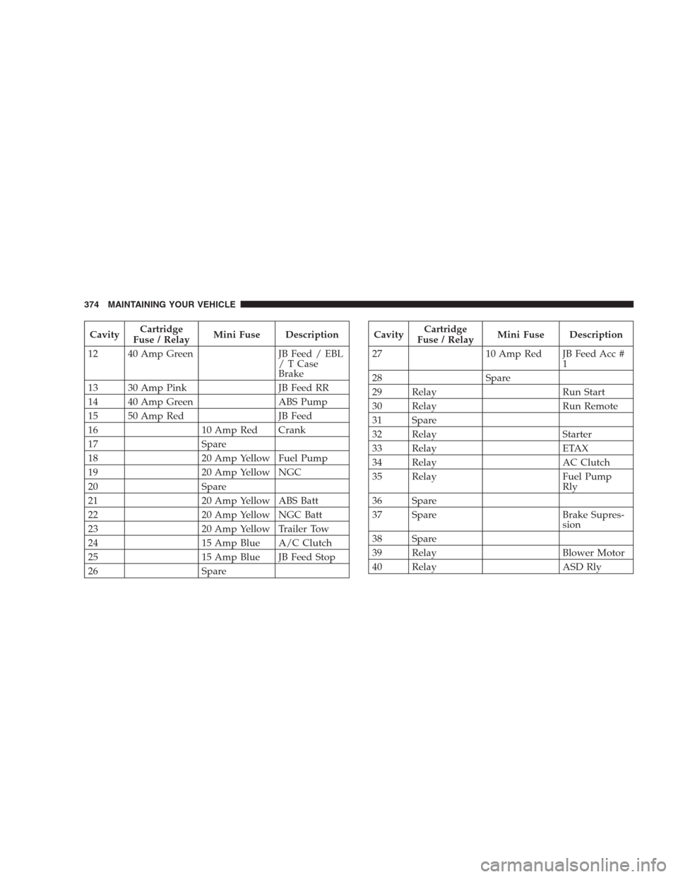
CavityCartridge
Fuse / RelayMini Fuse Description
12 40 Amp Green JB Feed / EBL
/TCase
Brake
13 30 Amp Pink JB Feed RR
14 40 Amp Green ABS Pump
15 50 Amp Red JB Feed
16 10 Amp Red Crank
17 Spare
18 20 Amp Yellow Fuel Pump
19 20 Amp Yellow NGC
20 Spare
21 20 Amp Yellow ABS Batt
22 20 Amp Yellow NGC Batt
23 20 Amp Yellow Trailer Tow
24 15 Amp Blue A/C Clutch
25 15 Amp Blue JB Feed Stop
26 SpareCavityCartridge
Fuse / RelayMini Fuse Description
27 10 Amp Red JB Feed Acc #
1
28 Spare
29 Relay Run Start
30 Relay Run Remote
31 Spare
32 Relay Starter
33 Relay ETAX
34 Relay AC Clutch
35 Relay Fuel Pump
Rly
36 Spare
37 Spare Brake Supres-
sion
38 Spare
39 Relay Blower Motor
40 Relay ASD Rly
374 MAINTAINING YOUR VEHICLE
Page 375 of 440
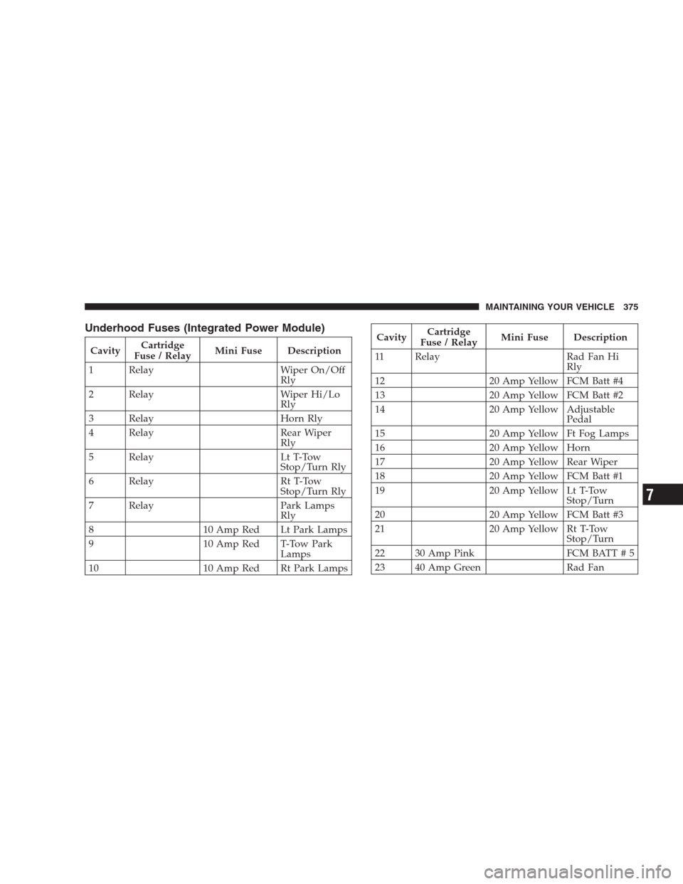
Underhood Fuses (Integrated Power Module)
CavityCartridge
Fuse / RelayMini Fuse Description
1 Relay Wiper On/Off
Rly
2 Relay Wiper Hi/Lo
Rly
3 Relay Horn Rly
4 Relay Rear Wiper
Rly
5 Relay Lt T-Tow
Stop/Turn Rly
6 Relay Rt T-Tow
Stop/Turn Rly
7 Relay Park Lamps
Rly
8 10 Amp Red Lt Park Lamps
9 10 Amp Red T-Tow Park
Lamps
10 10 Amp Red Rt Park Lamps
CavityCartridge
Fuse / RelayMini Fuse Description
11 Relay Rad Fan Hi
Rly
12 20 Amp Yellow FCM Batt #4
13 20 Amp Yellow FCM Batt #2
14 20 Amp Yellow Adjustable
Pedal
15 20 Amp Yellow Ft Fog Lamps
16 20 Amp Yellow Horn
17 20 Amp Yellow Rear Wiper
18 20 Amp Yellow FCM Batt #1
19 20 Amp Yellow Lt T-Tow
Stop/Turn
20 20 Amp Yellow FCM Batt #3
21 20 Amp Yellow Rt T-Tow
Stop/Turn
22 30 Amp Pink FCM BATT # 5
23 40 Amp Green Rad Fan
MAINTAINING YOUR VEHICLE 375
7
Page 376 of 440
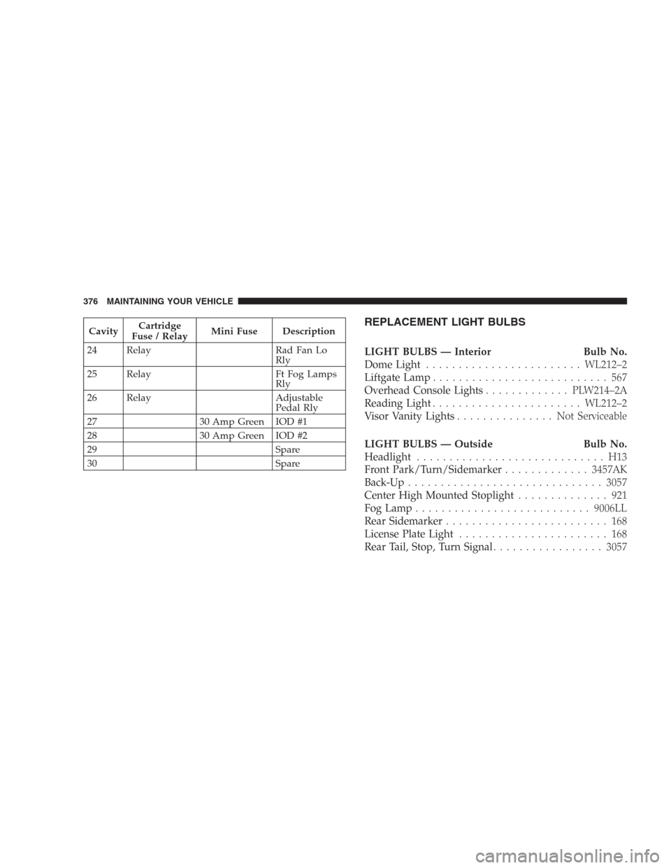
CavityCartridge
Fuse / RelayMini Fuse Description
24 Relay Rad Fan Lo
Rly
25 Relay Ft Fog Lamps
Rly
26 Relay Adjustable
Pedal Rly
27 30 Amp Green IOD #1
28 30 Amp Green IOD #2
29 Spare
30 SpareREPLACEMENT LIGHT BULBS
LIGHT BULBS — Interior Bulb No.
Dome Light........................WL212–2
Liftgate Lamp........................... 567
Overhead Console Lights............. PLW214–2A
Reading Light.......................WL212–2
Visor Vanity Lights............... NotServiceable
LIGHT BULBS — Outside Bulb No.
Headlight............................. H13
Front Park/Turn/Sidemarker.............3457AK
Back-Up..............................3057
Center High Mounted Stoplight.............. 921
Fog Lamp...........................9006LL
Rear Sidemarker......................... 168
License Plate Light....................... 168
Rear Tail, Stop, Turn Signal.................3057
376 MAINTAINING YOUR VEHICLE
Page 377 of 440
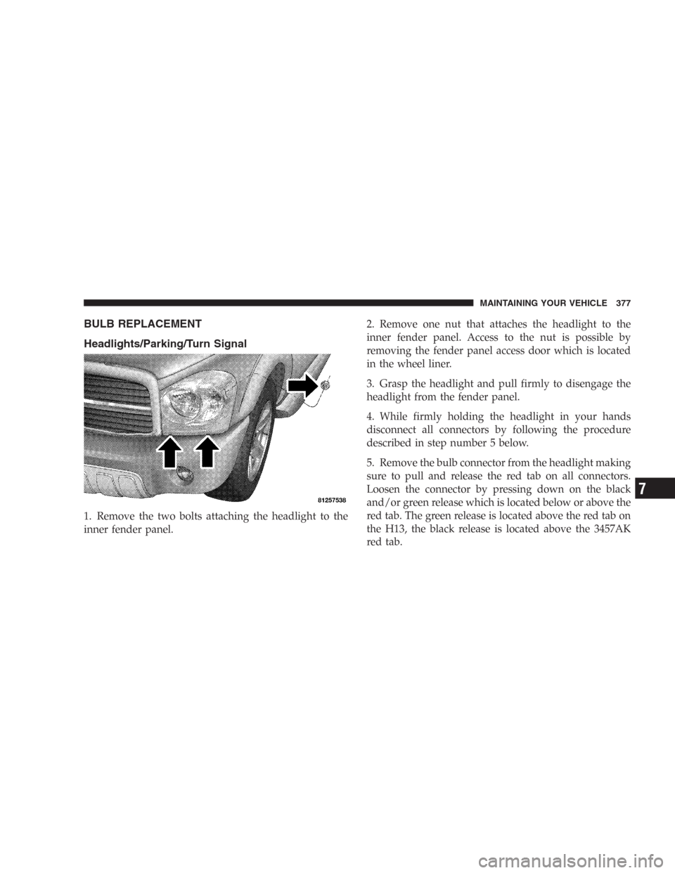
BULB REPLACEMENT
Headlights/Parking/Turn Signal
1. Remove the two bolts attaching the headlight to the
inner fender panel.2. Remove one nut that attaches the headlight to the
inner fender panel. Access to the nut is possible by
removing the fender panel access door which is located
in the wheel liner.
3. Grasp the headlight and pull firmly to disengage the
headlight from the fender panel.
4. While firmly holding the headlight in your hands
disconnect all connectors by following the procedure
described in step number 5 below.
5. Remove the bulb connector from the headlight making
sure to pull and release the red tab on all connectors.
Loosen the connector by pressing down on the black
and/or green release which is located below or above the
red tab. The green release is located above the red tab on
the H13, the black release is located above the 3457AK
red tab.
MAINTAINING YOUR VEHICLE 377
7
Page 378 of 440
6. Twist and remove socket from lamp.
7. Remove bulb from socket and replace.
NOTE:These are Halogen bulbs. Take care not to touch
the bulb with your fingers. Body oils from your fingers
could cause excessive heat build-up which reduces bulb
life.
Rear Side Marker, Tail Lights, Turn Signals And
Backup Lights — Replacement
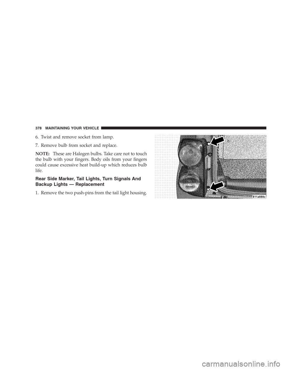
1. Remove the two push-pins from the tail light housing.
378 MAINTAINING YOUR VEHICLE
Page 379 of 440
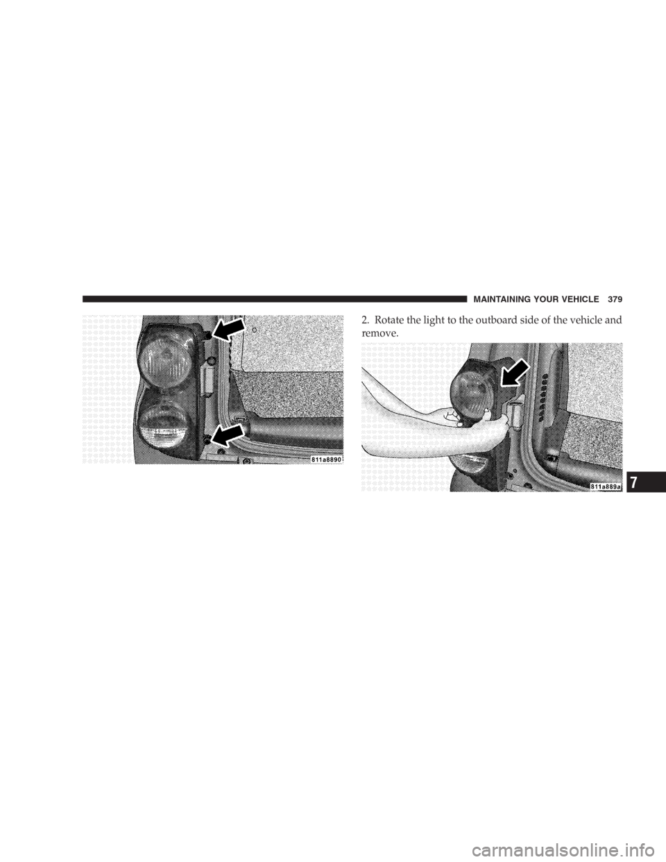
2. Rotate the light to the outboard side of the vehicle and
remove.
MAINTAINING YOUR VEHICLE 379
7
Page 380 of 440
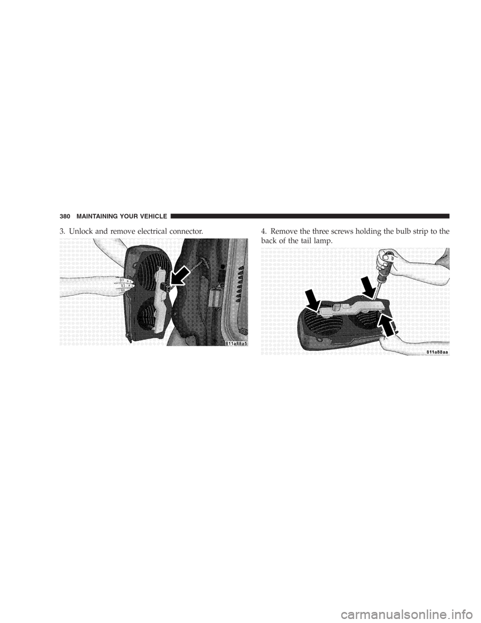
3. Unlock and remove electrical connector. 4. Remove the three screws holding the bulb strip to the
back of the tail lamp.
380 MAINTAINING YOUR VEHICLE
Trending: change language, octane, recreational towing, fuse, engine coolant, emergency towing, clock setting

