lock DODGE DURANGO 2012 3.G Owner's Manual
[x] Cancel search | Manufacturer: DODGE, Model Year: 2012, Model line: DURANGO, Model: DODGE DURANGO 2012 3.GPages: 140, PDF Size: 4.3 MB
Page 93 of 140
- Electronic Stability Control (ESC) Activation/Malfunction Indicator Light
• If the “ESC Activation/Malfunction Indicator Light” comes on continuously withthe engine running, a malfunction has been detected in the ESC system. If this
light remains on after several ignition cycles, and the vehicle has been driven
several miles (kilometers) at speeds greater than 30 mph (48 km/h), we
recommend you drive to the nearest service center and have the vehicle serviced
immediately.
• The “ESC Activation/Malfunction Indicator Light” starts to flash as soon as the tires lose traction and the ESC system becomes active. If the light begins to flash
during acceleration, ease up on the accelerator and apply as little throttle as
possible. Be sure to adapt your speed and driving to the prevailing road conditions.
The light also flashes when TCS is active. To improve the vehicle's traction when
starting off in deep snow, sand or gravel, it may be desirable to switch the ESC
system to Partial Off mode by momentarily pressing the ESC Off
switch located
below the climate controls, on the switch panel.
- Charging System Light
• This light shows the status of the electrical charging system. If the charging system light remains on, it means that the vehicle is experiencing a problem with
the charging system.
• We recommend you do not continue driving if the charging system light is on. Have the vehicle serviced immediately.
- Oil Pressure Warning Light
• This light indicates low engine oil pressure. If the light turns on while driving, stopthe vehicle and shut off the engine as soon as possible. A chime will sound for four
minutes when this light turns on.
• We recommend you do not operate the vehicle or engine damage will occur. Have the vehicle serviced immediately.
- Anti-Lock Brake (ABS) Light
• This light monitors the Anti-Lock Brake System (ABS).
• If the light is not on during starting, stays on, or turns on while driving, werecommend you drive to the nearest service center and have the vehicle serviced
immediately.
- Electronic Throttle Control (ETC) Light
• This light informs you of a problem with the Electronic Throttle Control (ETC)system.
• If a problem is detected, the light will come on while the engine is running. Cycle the ignition key when the vehicle has completely stopped and the shift lever is
placed in the PARK position; the light should turn off.
• If the light remains lit with the engine running, your vehicle will usually be drivable; however, see an authorized service center immediately. If the light is
flashing when the engine is running, immediate service is required and you may
experience reduced performance, an elevated/rough idle or engine stall and your
vehicle may require towing.
WHAT TO DO IN EMERGENCIES
91
Page 94 of 140
- Air Bag Warning Light
• If the light is not on during starting, stays on, or turns on while driving, have thevehicle serviced by an authorized service center immediately.
Fuel Cap/Loose Gas Cap Message
• If a “gas cap” message (shown as Check Gascap) appears, tighten the gas capuntil a “clicking” sound is heard.
• If the message continues to appear for more than three days after tightening the gas cap, have the vehicle serviced by an authorized service center immediately.
Oil Change Indicator
Message
• If an “oil change” message (shown as Oil Change Due) appears and a single chime sounds, it is time for your next required oil change.
Resetting The Light After Servicing
Vehicles Equipped With Keyless Enter-N-Go™ • Without pressing the brake pedal, push the ENGINE START/STOP button and cycle the ignition to the ON/RUN position (Do not start the engine.)
• Fully depress the accelerator pedal, slowly, three times within 10 seconds.
• Without pressing the brake pedal, push the ENGINE START/STOP button once to return the ignition to the OFF/LOCK position.
Vehicles Not Equipped With Keyless Enter-N-Go™
• Turn the ignition switch to the ON/RUN position (Do not start the engine.)
• Fully depress the accelerator pedal, slowly, three times within 10 seconds.
• Turn the ignition switch to the OFF/LOCK position.
IF YOUR ENGINE OVERHEATS
• In any of the following situations, you can reduce the potential for overheating by taking the appropriate action.
• On the highways — slow down.
• In city traffic — while stopped, place the transmission in NEUTRAL, but do not increase engine idle speed.
NOTE: There are steps that you can take to slow down an impending overheat
condition:
• If your air conditioner (A/C) is on, turn it off. The A/C system adds heat to the engine cooling system and turning the A/C off can help remove this heat.
• You can also turn the temperature control to maximum heat, the mode control to floor and the blower control to high. This allows the heater core to act as a
supplement to the radiator and aids in removing heat from the engine cooling
system.
WHAT TO DO IN EMERGENCIES
92
Page 99 of 140
Preparations For Jacking
1. Park the vehicle on a firm level surface, away from traffic for your safety.
2. Turn the engine off, place the transmission in PARK, fully depress the pedal tothe floor to set the parking brake, and activate the Hazard Warning flashers.
3. Block both the front and rear of the wheel diagonally opposite of the jacking position.
NOTE: Passengers should not remain in the
vehicle when the vehicle is being jacked.
Jacking Instructions
1. Loosen the lug nuts on the road wheel one turn while still on the ground, but
do not remove.
2. Determine the jacking location on the side of the vehicle. Attach the jack
tool with the hook, the extension and
the lug wrench to the jack as shown.
Jack Warning Label
WHAT TO DO IN EMERGENCIES
97
Page 101 of 140
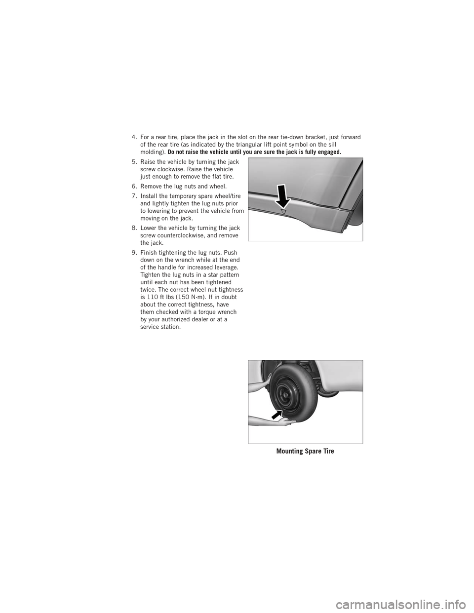
4. For a rear tire, place the jack in the slot on the rear tie-down bracket, just forwardof the rear tire (as indicated by the triangular lift point symbol on the sill
molding). Do not raise the vehicle until you are sure the jack is fully engaged.
5. Raise the vehicle by turning the jack screw clockwise. Raise the vehicle
just enough to remove the flat tire.
6. Remove the lug nuts and wheel.
7. Install the temporary spare wheel/tire and lightly tighten the lug nuts prior
to lowering to prevent the vehicle from
moving on the jack.
8. Lower the vehicle by turning the jack screw counterclockwise, and remove
the jack.
9. Finish tightening the lug nuts. Push down on the wrench while at the end
of the handle for increased leverage.
Tighten the lug nuts in a star pattern
until each nut has been tightened
twice. The correct wheel nut tightness
is 110 ft lbs (150 N·m). If in doubt
about the correct tightness, have
them checked with a torque wrench
by your authorized dealer or at a
service station.
Mounting Spare Tire
WHAT TO DO IN EMERGENCIES
99
Page 102 of 140
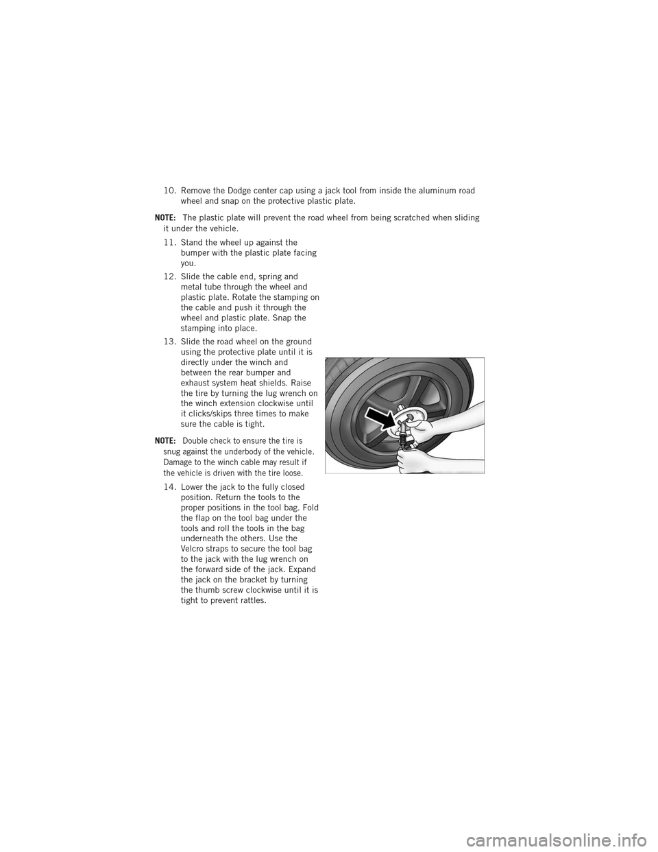
10. Remove the Dodge center cap using a jack tool from inside the aluminum roadwheel and snap on the protective plastic plate.
NOTE: The plastic plate will prevent the road wheel from being scratched when sliding
it under the vehicle.
11. Stand the wheel up against the bumper with the plastic plate facing
you.
12. Slide the cable end, spring and metal tube through the wheel and
plastic plate. Rotate the stamping on
the cable and push it through the
wheel and plastic plate. Snap the
stamping into place.
13. Slide the road wheel on the ground using the protective plate until it is
directly under the winch and
between the rear bumper and
exhaust system heat shields. Raise
the tire by turning the lug wrench on
the winch extension clockwise until
it clicks/skips three times to make
sure the cable is tight.
NOTE:
Double check to ensure the tire is
snug against the underbody of the vehicle.
Damage to the winch cable may result if
the vehicle is driven with the tire loose.
14. Lower the jack to the fully closed position. Return the tools to the
proper positions in the tool bag. Fold
the flap on the tool bag under the
tools and roll the tools in the bag
underneath the others. Use the
Velcro straps to secure the tool bag
to the jack with the lug wrench on
the forward side of the jack. Expand
the jack on the bracket by turning
the thumb screw clockwise until it is
tight to prevent rattles.
WHAT TO DO IN EMERGENCIES
100
Page 103 of 140
15. Reinstall the plastic plug into the floor of the cargo area. Roll up and store theJack, Tool Kit and Tire Changing Instructions. Reinstall the cover for the jack in
the rear storage bin.
NOTE: The plastic thumb screw being on the right and the position of the lug wrench
before the velcro straps go around the fully closed jack.
16. Remove the blocks/rocks from the opposite tire.
17. Have the aluminum road wheel and tire repaired as soon as possible and
properly secure the spare tire, jack
and tool kit.
Road Tire Installation
1. Mount the road tire on the axle.
2. Install the remaining lug nuts with thecone shaped end of the nut toward
the wheel. Lightly tighten the lug
nuts.
3. Lower the vehicle to the ground by turning the jack handle
counterclockwise.
4. Finish tightening the lug nuts. Push down on the wrench while at the end of the handle for increased leverage. Tighten the lug nuts in a star pattern until each nut
has been tightened twice. The correct tightness of each lug nut is 110 ft/lbs
(150 N·m). If in doubt about the correct tightness, have them checked with a
torque wrench by your authorized dealer or service station.
5. After 25 miles (40 km) check the lug nut torque with a torque wrench to ensure that all lug nuts are properly seated against the wheel.
CAUTION!
• Do not use power tools to winch the tire up or down. Impact type tools candamage the winch mechanism.
• Do not attempt to raise the vehicle by jacking on locations other than those indicated in the Jacking Instructions for this vehicle.
• Be sure to mount the spare tire with the valve stem facing outward. The vehicle could be damaged if the spare tire is mounted incorrectly.
WHAT TO DO IN EMERGENCIES
101
Page 104 of 140
WARNING!
• Do not attempt to change a tire on the side of the vehicle close to movingtraffic. Pull far enough off the road to avoid the danger of being hit when
operating the jack or changing the wheel.
• Being under a jacked-up vehicle is dangerous. The vehicle could slip off the jack and fall on you. You could be crushed. Never put any part of your body
under a vehicle that is on a jack. If you need to get under a raised vehicle,
take it to a service center where it can be raised on a lift.
• The jack is designed to be used as a tool for changing tires only. The jack should not be used to lift the vehicle for service purposes. The vehicle should
be jacked on a firm level surface only. Avoid ice or slippery areas.
• Always park on a firm, level surface as far from the edge of the roadway as possible before raising the vehicle.
• Turn on the Hazard Warning flasher.
• Block the wheel diagonally opposite the wheel to be raised.
• Set the parking brake firmly and set the automatic transmission in PARK.
• Never start or run the engine with the vehicle on a jack.
• Do not let anyone sit in the vehicle when it is on a jack.
• Do not get under the vehicle when it is on a jack.
• Only use the jack in the positions indicated and for lifting this vehicle during a tire change.
• If working on or near a roadway, be extremely careful of motor traffic.
• To assure that spare tires, flat or inflated, are securely stowed, spares must be stowed with the valve stem facing the ground.
• Carefully follow these tire changing warnings to help prevent personal injury or damage to your vehicle:
• Raising the vehicle higher than necessary can make the vehicle less stable. It could slip off the jack and hurt someone near it. Raise the vehicle only
enough to remove the tire.
• To avoid the risk of forcing the vehicle off the jack, do not fully tighten the wheel nuts until the vehicle has been lowered. Failure to follow this warning
may result in personal injury.
• Do not use power tools to winch the tire up or down. Impact-type tools may damage the winch mechanism.
• A loose tire or jack, thrown forward in a collision or hard stop could endanger the occupants of the vehicle. Always stow the jack parts and the spare tire in
the places provided.
• To avoid the risk of forcing the vehicle off the jack, do not tighten the lug nuts fully until the vehicle is lowered to the ground.
WHAT TO DO IN EMERGENCIES
102
Page 111 of 140
OPENING THE HOOD
• Pull the hood release lever locatedbelow the steering wheel at the base of
the instrument panel.
• Reach into the opening beneath the center of the hood and move the safety
latch lever while lifting the hood at the
same time.
WARNING!
Be sure the hood is fully latched before driving your vehicle. If the hood is not
fully latched, it could open when the vehicle is in motion and block your vision.
Failure to follow this warning could result in serious injury or death.
FUEL DOOR RELEASE
• The fuel door release button is locatedon the instrument panel below the
headlight switch.
• Push the button once and release to open the fuel door.
MAINTAINING YOUR VEHICLE
109
Page 121 of 140
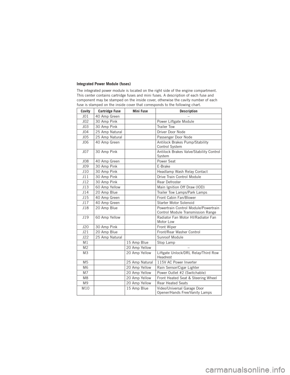
Integrated Power Module (fuses)
The integrated power module is located on the right side of the engine compartment.
This center contains cartridge fuses and mini fuses. A description of each fuse and
component may be stamped on the inside cover, otherwise the cavity number of each
fuse is stamped on the inside cover that corresponds to the following chart.
Cavity Cartridge Fuse Mini FuseDescription
J01 40 Amp Green –
J02 30 Amp Pink Power Liftgate Module
J03 30 Amp Pink Trailer Tow
J04 25 Amp Natural Driver Door Node
J05 25 Amp Natural Passenger Door Node
J06 40 Amp Green Antilock Brakes Pump/Stability
Control System
J07 30 Amp Pink Antilock Brakes Valve/Stability Control
System
J08 40 Amp Green Power Seat
J09 30 Amp Pink E-Brake
J10 30 Amp Pink Headlamp Wash Relay Contact
J11 30 Amp Pink Drive Train Control Module
J12 30 Amp Pink Rear Defroster
J13 60 Amp Yellow Main Ignition Off Draw (IOD)
J14 20 Amp Blue Trailer Tow Lamps/Park Lamps
J15 40 Amp Green Front Cabin Fan/Blower
J17 40 Amp Green Starter Motor Solenoid
J18 20 Amp Blue Powertrain Control Module/Powertrain
Control Module Transmission Range
J19 60 Amp Yellow Radiator Fan Motor HI/Radiator Fan
Motor Low
J20 30 Amp Pink Front Wiper
J21 20 Amp Blue Front/Rear Washer Control
J22 25 Amp Natural Sunroof Module
M1 15 Amp Blue Stop Lamp
M2 20 Amp Yellow –
M3 20 Amp Yellow Liftgate Unlock/DRL Relay/Third Row
Headrest
M5 25 Amp Natural 115V AC Power Inverter
M6 20 Amp Yellow Rain Sensor/Cigar Lighter
M7 20 Amp Yellow Power Outlet #2 (Switchable)
M8 20 Amp Yellow Front Heated Seat & Steering Wheel
M9 20 Amp Yellow Rear Heated Seats
M10 15 Amp Blue Video/Universal Garage Door
Opener/Hands Free/Vanity Lamps
MAINTAINING YOUR VEHICLE
119
Page 122 of 140
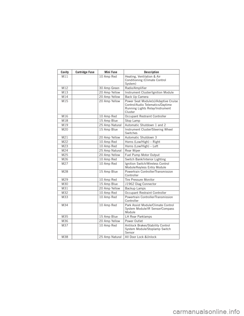
Cavity Cartridge Fuse Mini FuseDescription
M11 10 Amp Red Heating, Ventilation & Air
Conditioning (Climate Control
System)
M12 30 Amp Green Radio/Amplifier
M13 20 Amp Yellow Instrument Cluster/Ignition Module
M14 20 Amp Yellow Back Up Camera
M15 20 Amp Yellow Power Seat Module(s)/Adaptive Cruise
Control/Audio Telematics/Daytime
Running Lights Relay/Instrument
Cluster
M16 10 Amp Red Occupant Restraint Controller
M18 15 Amp Blue Stop Lamp
M19 25 Amp Natural Automatic Shutdown 1 and 2
M20 15 Amp Blue Instrument Cluster/Steering Wheel
Switches
M21 20 Amp Yellow Automatic Shutdown 3
M22 10 Amp Red Horns (Low/High) – Right
M23 10 Amp Red Horns (Low/High) – Left
M24 25 Amp Natural Rear Wiper
M25 20 Amp Yellow Fuel Pump Motor Output
M26 10 Amp Red Switch Bank/Interior Lighting
M27 10 Amp Red Ignition Switch/Wireless Control
Module/Keyless Entry Module
M28 15 Amp Blue Powertrain Controller/Transmission
Controller
M29 10 Amp Red Tire Pressure Monitor
M30 15 Amp Blue J1962 Diag Connector
M31 20 Amp Yellow Backup Lamps
M32 10 Amp Red Occupant Restraint Controller
M33 10 Amp Red Powertrain Controller/Transmission
Controller
M34 10 Amp Red Park Assist Module/Climate Control
System Module/IR Sensor/Compass
Module
M35 15 Amp Blue LH Rear Parklamps
M36 20 Amp Yellow Power Outlet
M37 10 Amp Red Antilock Brakes/Stability Control
System Module/Stoplamp Switch
Sensor
M38 25 Amp Natural All Door Lock &Unlock
MAINTAINING YOUR VEHICLE
120