ECU DODGE DURANGO 2013 3.G User Guide
[x] Cancel search | Manufacturer: DODGE, Model Year: 2013, Model line: DURANGO, Model: DODGE DURANGO 2013 3.GPages: 140, PDF Size: 4.38 MB
Page 11 of 140
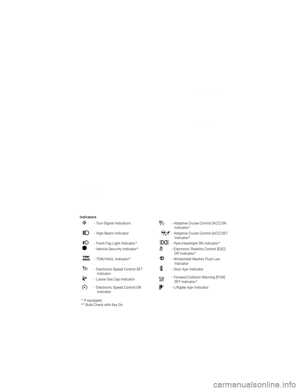
Indicators
- Turn Signal Indicators- Adaptive Cruise Control (ACC) ONIndicator*
- High Beam Indicator- Adaptive Cruise Control (ACC) SETIndicator*
- Front Fog Light Indicator*- Park/Headlight ON Indicator*
- Vehicle Security Indicator*- Electronic Stability Control (ESC)Off Indicator*
- TOW/HAUL Indicator*- Windshield Washer Fluid LowIndicator
- Electronic Speed Control SETIndicator- Door Ajar Indicator
- Loose Gas Cap Indicator- Forward Collision Warning (FCW)OFF Indicator*
- Electronic Speed Control ONIndicator- Liftgate Ajar Indicator
* If equipped
** Bulb Check with Key On
CONTROLS AT A GLANCE
9
Page 14 of 140
WARNING!
• Never use the PARK position as a substitute for the parking brake. Always apply theparking brake fully when parked to guard against vehicle movement and possible
injury or damage.
• When leaving the vehicle, always remove the key fob from the ignition and lock your
vehicle.
• Never leave children alone in a vehicle, or with access to an unlocked vehicle.
Allowing children to be in a vehicle unattended is dangerous for a number of reasons.
A child or others could be seriously or fatally injured. Children should be warned not
to touch the parking brake, brake pedal or the shift lever.
• Do not leave the key fob in or near the vehicle, or in a location accessible to children,
and do not leave a vehicle equipped with Keyless Enter-N-Go™ in the ACC or ON/RUN
mode. A child could operate power windows, other controls, or move the vehicle.
REMOTE START
• Press the REMOTE START buttonx2on the Key Fob twice within five seconds. Pressing
the REMOTE START button a third time shuts the engine off.
• To drive the vehicle, with a valid Keyless Enter-N-Go™ Key Fob within 5 ft (1.5m) of the driver's side of the vehicle, grab the front driver door handle to unlock the driver's door
automatically, then press the Start/Stop switch. Or press the UNLOCK button, insert the
Key Fob in the ignition and turn to the ON/RUN position.
• With remote start, the engine will only run for 15 minutes (timeout) unless the ignition is placed in the ON/RUN position.
• The vehicle must be started with the Key Fob after two consecutive timeouts.
WARNING!
• Do not start or run an engine in a closed garage or confined area. Exhaust gas contains Carbon Monoxide (CO) which is odorless and colorless. Carbon Monoxide is
poisonous and can cause you or others to be severely injured or killed when inhaled.
• Keep Key Fob transmitters away from children. Operation of the Remote Start
System, windows, door locks or other controls could cause you and others to be
severely injured or killed.
GETTING STARTED
12
Page 16 of 140
• If a Key Fob is detected in the vehicle when locking the vehicle using the power door lockswitch, the doors and liftgate will unlock and the horn will chirp three times. On the third
attempt, your Key Fob can be locked inside the vehicle.
•
After pressing the Keyless Enter-N-Go™ LOCK button, you must wait 2 seconds before you
can lock or unlock the vehicle using the door handle. This is done to allow you to check if the
vehicle is locked by pulling the door handle, without the vehicle reacting and unlocking.
• If a Keyless Enter-N-Go™ door handle has not been used for 72 hours, the Keyless Enter-N-Go™ feature for that handle may time out. Pulling the deactivated front door
handle will reactivate the door handle's Keyless Enter-N-Go™ feature.
Lock or Unlock the Liftgate
• With a valid Keyless Enter-N-Go™ Key Fob within 3 ft. (1.0m) of the liftgate, press the
button located to the right of the liftgate
handle to unlock the liftgate. Press the
button a second time to lock the liftgate.
NOTE:
Refer to your Owner's Manual on the DVD for
further information.
Installing And Removing The ENGINE START/STOP Button
Installing The Button
• Remove the Key Fob from the ignition switch.
• Insert the ENGINE START/STOP button into the ignition switch with the lettering facing up and readable.
• Press firmly on the center of the button to secure it into position.
Removing The Button
• The ENGINE START/STOP button can be removed from the ignition switch for Key
Fob use.
•
Insert the metal part of the emergency key
under the chrome bezel at the 6 o’clock
position and gently pry the button loose.
NOTE:
The ENGINE START/STOP button should only
be removed or inserted with the ignition in
the LOCK position (OFF position for Keyless
Enter-N-Go™).
GETTING STARTED
14
Page 20 of 140
WARNING!
• Relying on the air bags alone could lead to more severe injuries in a collision. The airbags work with your seat belt to restrain you properly. In some collisions, the air bags
won't deploy at all. Always wear your seat belts even though you have air bags.
• Being too close to the steering wheel or instrument panel during Advanced Front Air
Bag deployment could cause serious injury, including death. Air bags need room to
inflate. Sit back, comfortably extending your arms to reach the steering wheel or
instrument panel.
• Supplemental Side Air Bag Inflatable Curtains and Supplemental Seat-Mounted Side
Air Bags need room to inflate. Do not lean against the door or window. Sit upright in
the center of the seat.
•
Being too close to the Supplemental Side Air Bag Inflatable Curtain and/or Seat-
Mounted Side Air Bag during deployment could cause you to be severely injured or killed.
• Do not drive your vehicle after the air bags have deployed. If you are involved in
another collision, the air bags will not be in place to protect you.
• After any collision, the vehicle should be taken to an authorized dealer immediately.
CHILD RESTRAINTS
• Children 12 years and under should ride properly buckled up in a rear seat, if available. According to crash statistics, children are safer when properly restrained in the rear
seats rather than in the front.
• Every state in the United States and all Canadian provinces require that small children ride in proper restraint systems. This is the law, and you can be prosecuted for ignoring it.
NOTE:
• For additional information, refer to www.seatcheck.org or call 1–866–SEAT-CHECK (1–866–732–8243).
•
Canadian residents, should refer to Transport Canada’s website for additional
informationhttp://www.tc.gc.ca/eng/roadsafety/safedrivers-childsafety-index-53.htm.
Installing The LATCH - Compatible Child Restraint System
• Your vehicle's second row passenger seats are equipped with the child restraint anchor- age system called LATCH, which stands for Lower Anchors and Tether for CHildren.
• Second and third row seating positions have lower anchorages that are capable of accommodating LATCH-compatible child seats having flexible, webbing-mounted lower
attachments.
• Child seats with fixed lower attachments must be installed in the outboard positions only.
• The vehicle's seat belt must be used for the center position.
GETTING STARTED
18
Page 22 of 140
Installing The Child Restraint Using The Vehicle Seat Belts
•
To install a child restraint, first pull enough of the seat belt webbing from the retractor to route
it through the belt path of the child restraint and slide the seat belt latch plate into the buckle.
• Next, extract all the seat belt webbing out of the retractor and then allow the belt to retract into the retractor. Finally, pull on any excess webbing to tighten the lap portion
around the child restraint. Any seat belt system will loosen with time, so check the belt
occasionally, and pull it tight if necessary.
• Once you have completed securing the child restraint with the seat belt, secure the top tether strap. The tether strap should be attached to the tether anchor on the rear of the
seatback (behind the gap panel) using the most direct path. DO NOT USEthe cargo tie
down loops located on the load floor.
WARNING!
• In a collision, an unrestrained child, even a tiny baby, can become a projectile inside the vehicle. The force required to hold even an infant on your lap could become so
great that you could not hold the child, no matter how strong you are. The child and
others could be severely injured or killed. Any child riding in your vehicle should be in
a proper restraint for the child's size.
• Improper installation of a child restraint to the LATCH anchorages can lead to failure
of an infant or child restraint. The child could be severely injured or killed. Follow the
manufacturer’s directions exactly when installing an infant or child restraint.
• An incorrectly anchored tether strap could lead to increased head motion and
possible injury to the child. Use only the anchor positions directly behind the child
seat to secure a child restraint top tether strap.
• Rearward-facing child seats must never be used in the front seat of a vehicle with a
front passenger air bag. An air bag deployment could cause severe injury or death to
infants in this position.
GETTING STARTED
20
Page 42 of 140
POWER SUNROOF
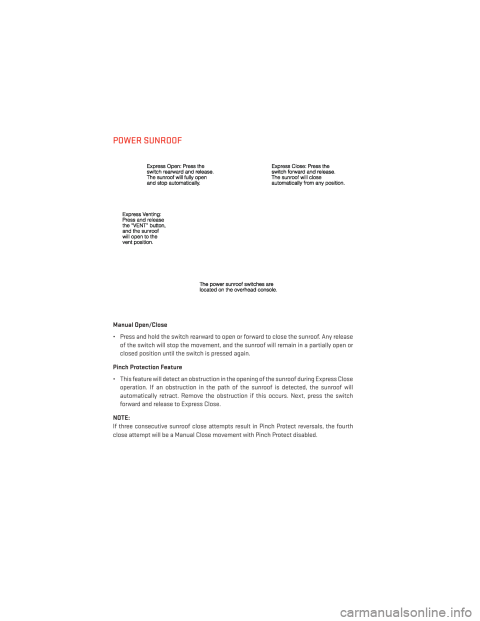
Manual Open/Close
• Press and hold the switch rearward to open or forward to close the sunroof. Any releaseof the switch will stop the movement, and the sunroof will remain in a partially open or
closed position until the switch is pressed again.
Pinch Protection Feature
• This feature will detect an obstruction in the opening of the sunroof during Express Close operation. If an obstruction in the path of the sunroof is detected, the sunroof will
automatically retract. Remove the obstruction if this occurs. Next, press the switch
forward and release to Express Close.
NOTE:
If three consecutive sunroof close attempts result in Pinch Protect reversals, the fourth
close attempt will be a Manual Close movement with Pinch Protect disabled.
OPERATING YOUR VEHICLE
40
Page 43 of 140
WARNING!
• Never leave children unattended in a vehicle, and do not leave the key in the ignitionswitch (or leave the ignition of a vehicle equipped with Keyless Enter-N-Go™ in the
ACC or ON/Run position). Occupants, particularly unattended children, can become
entrapped by the power sunroof while operating the power sunroof switch. Such
entrapment may result in serious injury or death.
• In a collision, there is a greater risk of being thrown from a vehicle with an open
sunroof. You could also be severely injured or killed. Always fasten your seat belt
properly and make sure all passengers are properly secured.
• Do not allow small children to operate the sunroof. Never allow your fingers, other
body parts, or any object to project through the sunroof opening. Injury may result.
WIND BUFFETING
• Wind buffeting can be described as a helicopter-type percussion sound. If buffetingoccurs with the rear windows open, adjust the front and rear windows together.
• If buffeting occurs with the sunroof open, adjust the sunroof opening, or adjust any window. This will minimize buffeting.
OPERATING YOUR VEHICLE
41
Page 84 of 140
UNIVERSAL GARAGE DOOR OPENER (HomeLink®)
•HomeLink® replaces up to three hand-held transmitters that operate devices such as
garage door openers, motorized gates, lighting or home security systems. The HomeLink®
unit is powered by your vehicles 12 Volt battery.
• The HomeLink® buttons that are located in the overhead console or sunvisor designate the three different HomeLink® channels.
• The HomeLink® indicator is located above the center button.
Before You Begin Programming HomeLink®
•
Be sure that your vehicle is parked outside of
the garage before you begin programming.
•For more efficient programming and accu-
rate transmission of the radio-frequency
signal it is recommended that a new battery
be placed in the hand-held transmitter of
the device that is being programmed to the
HomeLink® system.
•Erase all channels before you begin pro-
gramming. To erase the channels, place the
ignition switch into the ON/RUN position,
then press and hold the two outside
HomeLink® buttons (I and III) for up to
20 seconds or until the red indicator flashes.
NOTE:
• Erasing all channels should only be performed when programming HomeLink® for the
first time. Do not erase channels when programming additional buttons.
• If you have any problems, or require assistance, please call toll-free 1–800–355– 3515 or, on the Internet at www.HomeLink.com for information or assistance.
Programming A Rolling Code
• For programming Garage Door Openers that were manufactured after 1995. These Garage Door Openers can be identified by the “LEARN” or “TRAIN” button located where
the hanging antenna is attached to the Garage Door Opener. It is NOT the button that is
normally used to open and close the door. The name and color of the button may vary by
manufacturer.
• Place the ignition switch into the ON/RUN position.
• Place the hand-held transmitter 1 to 3 in (3 to 8 cm) away from the HomeLink® button you wish to program while keeping the HomeLink® indicator light in view.
• Simultaneously press and hold both the HomeLink® button you want to program and the hand-held transmitter button.
ELECTRONICS
82
Page 86 of 140
Using HomeLink®
•T
o operate, press and release the programmed HomeLink® button. Activation will now occur
for the programmed device (i.e., garage door opener, gate operator, security system, entry door
lock, home/office lighting, etc.,). The hand-held transmitter of the device may also be used at
any time.
WARNING!
• Your motorized door or gate will open and close while you are programming the
universal transceiver. Do not program the transceiver if people or pets are in the path
of the door or gate.
• Do not run your vehicle in a closed garage or confined area while programming the transceiver. Exhaust gas from your vehicle contains Carbon Monoxide (CO) which is
odorless and colorless. Carbon Monoxide is poisonous when inhaled and can cause
you and others to be severely injured or killed.
POWER INVERTER
• There is a 115 Volt, 150 Watt power inverteroutlet located on the back of the center
console. This outlet can power cellular
phones, electronics and other low power
devices requiring power up to 150 Watts.
• Press the switch located in the switch bank on the lower instrument panel to
turn the power inverter on. The indicator
light will turn on to indicate the inverter is
producing AC power.
•
Press the switch again to turn the power
inverter off. The indicator light will turn off.
NOTE:
The power inverter is designed with built-in
overload protection. If the power rating of
150 Watts is exceeded, the power inverter will
automatically shut down. Once the electrical device has been removed from the outlet, the
inverter should automatically reset. If the power rating exceeds approximately 170 Watts, the
power inverter may have to be reset manually. To reset the inverter manually, unplug the device
and plug it in again. To avoid overloading the circuit, check the power ratings on electrical devices
prior to using the inverter.
ELECTRONICS
84
Page 107 of 140
14. Lower the jack to the fully closed position. Return the tools to the proper positions in thetool bag. Fold the flap on the tool bag under the tools and roll the tools in the bag
underneath the others. Use the Velcro straps to secure the tool bag to the jack with the
lug wrench on the forward side of the jack. Expand the jack on the bracket by turning the
thumb screw clockwise until it is tight to prevent rattles.
15.
Reinstall the plastic plug into the floor of
the cargo area. Roll up and store the Jack,
Tool Kit and Tire Changing Instructions.
Reinstall the cover for the jack in the rear
storage bin.
NOTE:
The plastic thumb screw being on the right
and the position of the lug wrench before the
velcro straps go around the fully closed jack.
16.
Remove the blocks/rocks from the oppo-
site tire.
17.Have the aluminum road wheel and tire
repaired as soon as possible and properly
secure the spare tire, jack and tool kit.
Road Tire Installation
1. Mount the road tire on the axle.
2. Install the remaining lug nuts with the cone shaped end of the nut toward the
wheel. Lightly tighten the lug nuts.
3. Lower the vehicle to the ground by turning the jack handle counterclockwise.
4. Finish tightening the lug nuts. Push down on the wrench while at the end of the handle for increased leverage. Tighten the lug nuts in a star pattern until each nut has been
tightened twice. The correct tightness of each lug nut is 110 ft/lbs (150 N·m). If in doubt
about the correct tightness, have them checked with a torque wrench by your authorized
dealer or service station.
5. After 25 miles (40 km) check the lug nut torque with a torque wrench to ensure that all lug nuts are properly seated against the wheel.
CAUTION!
• Do not use power tools to winch the tire up or down. Impact type tools can damage the winch mechanism.
• Do not attempt to raise the vehicle by jacking on locations other than those indicated
in the Jacking Instructions for this vehicle.
• Be sure to mount the spare tire with the valve stem facing outward. The vehicle could
be damaged if the spare tire is mounted incorrectly.
WHAT TO DO IN EMERGENCIES
105