instrument cluster DODGE DURANGO 2013 3.G User Guide
[x] Cancel search | Manufacturer: DODGE, Model Year: 2013, Model line: DURANGO, Model: DODGE DURANGO 2013 3.GPages: 140, PDF Size: 4.38 MB
Page 3 of 140
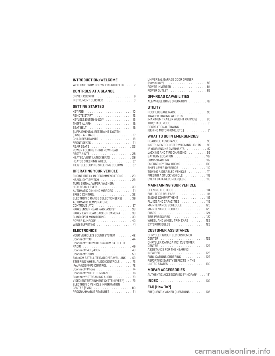
INTRODUCTION/WELCOME
WELCOME FROM CHRYSLER GROUP LLC . . . 2
CONTROLS AT A GLANCE
DRIVER COCKPIT................6
INSTRUMENT CLUSTER .............8
GETTING STARTED
KEYFOB .....................10
REMOTE START.................12
KEYLESS ENTER-N-GO™ ............13
THEFT ALARM .................16
SEATBELT ...................16
SUPPLEMENTAL RESTRAINT SYSTEM
(SRS)—AIRBAGS ................17
CHILD RESTRAINTS ..............18
FRONT SEATS ..................21
REARSEATS ..................23
POWER FOLDING THIRD ROW HEAD
RESTRAINTS ..................25
HEATED/VENTILATED SEATS .........26
HEATED STEERING WHEEL ..........27
TILT/TELESCOPING STEERING COLUMN . . . 27
OPERATING YOUR VEHICLE
ENGINE BREAK-IN RECOMMENDATIONS . . . 29
HEADLIGHT SWITCH ..............29
TURN SIGNAL/WIPER/WASHER/
HIGH BEAM LEVER ...............30
AUTOMATIC DIMMING MIRRORS ........31
SPEED CONTROL ...............32
ELECTRONIC RANGE SELECTION (ERS) . . . 36
AUTOMATIC TEMPERATURE
CONTROLS (ATC) ................37
PARKSENSE® REAR PARK ASSIST ......38
PARKVIEW® REAR BACK-UP CAMERA ....39
BLIND SPOT MONITORING ...........39
POWER SUNROOF ...............40
WIND BUFFETING ................41
ELECTRONICS
YOUR VEHICLE'S SOUND SYSTEM ......42
Uconnect® 130 .................44
Uconnect® 130 WITH SiriusXM SATELLITE
RADIO ......................46
Uconnect® 430/430N .............48
Uconnect® 730N ................58
SiriusXM SATELLITE RADIO/TRAVEL LINK . . 69
STEERING WHEEL AUDIO CONTROLS .....72
iPod®/USB/MP3 CONTROL ..........72
Uconnect® Phone ................74
Uconnect® VOICE COMMAND .........76
Bluetooth® STREAMING AUDIO ........79
VIDEO ENTERTAINMENT SYSTEM (VES™) . . . 79
ELECTRONIC VEHICLE INFORMATION
CENTER (EVIC) .................80
PROGRAMMABLE FEATURES .........81UNIVERSAL GARAGE DOOR OPENER
(HomeLink®)
..................82
POWER INVERTER ...............84
POWER OUTLET ................85
OFF-ROAD CAPABILITIES
ALL-WHEEL DRIVE OPERATION ........87
UTILITY
ROOF LUGGAGE RACK.............89
TRAILER TOWING WEIGHTS
(MAXIMUM TRAILER WEIGHT RATINGS) . . . 90
TOW/HAUL MODE ...............91
RECREATIONAL TOWING
(BEHIND MOTORHOME, ETC.) .........91
WHAT TO DO IN EMERGENCIES
ROADSIDE ASSISTANCE............93
INSTRUMENT CLUSTER WARNING LIGHTS . . 93
IF YOUR ENGINE OVERHEATS .........97
JACKING AND TIRE CHANGING ........98
BATTERY LOCATION ..............107
JUMP-STARTING ...............107
EMERGENCY TOW HOOKS ..........109
SHIFT LEVER OVERRIDE ...........110
TOWING A DISABLED VEHICLE ........111
FREEING A STUCK VEHICLE .........112
EVENT DATA RECORDER (EDR) ........113
MAINTAINING YOUR VEHICLE
OPENING THE HOOD..............114
FUEL DOOR RELEASE .............114
ENGINE COMPARTMENT ...........116
FLUIDS AND CAPACITIES ...........118
MAINTENANCE SCHEDULE .........120
MAINTENANCE RECORD ...........123
FUSES .....................124
TIRE PRESSURES ...............127
WHEEL AND WHEEL TRIM CARE ......128
EXTERIOR BULBS ..............128
CUSTOMER ASSISTANCE
CHRYSLER GROUP LLC CUSTOMER
CENTER....................129
CHRYSLER CANADA INC. CUSTOMER
CENTER ....................129
ASSISTANCE FOR THE HEARING
IMPAIRED ...................129
PUBLICATIONS ORDERING ..........129
REPORTING SAFETY DEFECTS IN THE
UNITEDSTATES ................130
MOPAR ACCESSORIES
AUTHENTIC ACCESSORIES BY MOPAR® . . . 131
INDEX....................132
FAQ (How To?)
FREQUENTLY ASKED QUESTIONS ......135
TABLE OF CONTENTS
Page 9 of 140

A. Headlight Switch pg. 29
B. Turn Signal/Wiper/Washer/High BeamsLever (behind steering wheel) pg. 30
C. Instrument Cluster pg. 8
D. Electronic Vehicle Information Center (EVIC) Display pg. 8
E. Ignition Switch (behind steering wheel) pg. 15
F. Audio System (touch-screen-radio shown) pg. 42
G. Climate Controls pg. 37 H. SWITCH PANEL
• Electronic Stability Control pg. 95
• Tow/Haul pg. 91
• Heated Steering Wheel pg. 27
• Hazard Switch
• Power Inverter pg. 84
• ParkSense® pg. 38
• Power Folding Third Row HeadRestraints pg. 25
I. Transmission Gear Selector J. Power Outlet pg. 85
K. Speed Control pg. 32
L. EVIC Controls pg. 80
M. Fuel Door Release pg. 114
N. Parking Brake Release
O. Power Mirrors
P. Power Windows
Q. Power Door Locks
R. Driver's Memory Buttons pg. 21
CONTROLS AT A GLANCE
7
Page 10 of 140
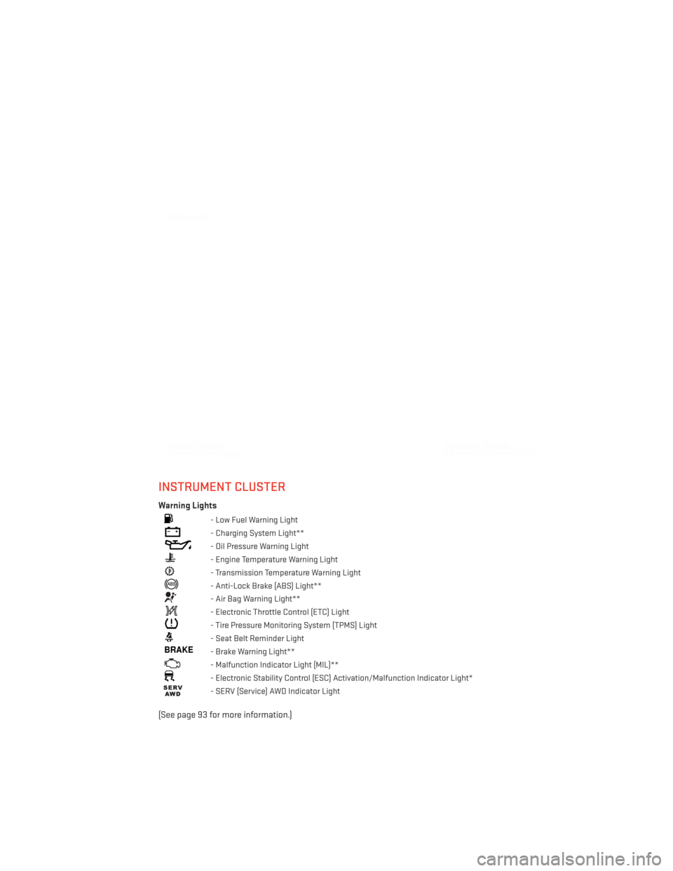
INSTRUMENT CLUSTER
Warning Lights
- Low Fuel Warning Light
- Charging System Light**
- Oil Pressure Warning Light
- Engine Temperature Warning Light
- Transmission Temperature Warning Light
- Anti-Lock Brake (ABS) Light**
- Air Bag Warning Light**
- Electronic Throttle Control (ETC) Light
- Tire Pressure Monitoring System (TPMS) Light
- Seat Belt Reminder Light
BRAKE- Brake Warning Light**
- Malfunction Indicator Light (MIL)**
- Electronic Stability Control (ESC) Activation/Malfunction Indicator Light*
- SERV (Service) AWD Indicator Light
(See page 93 for more information.)
CONTROLS AT A GLANCE
8
Page 34 of 140
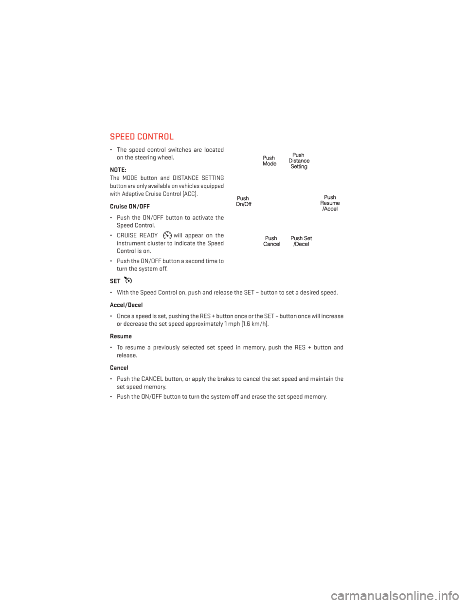
SPEED CONTROL
• The speed control switches are locatedon the steering wheel.
NOTE:
The MODE button and DISTANCE SETTING
button are only available on vehicles equipped
with Adaptive Cruise Control (ACC).
Cruise ON/OFF
• Push the ON/OFF button to activate the Speed Control.
• CRUISE READY
will appear on the
instrument cluster to indicate the Speed
Control is on.
• Push the ON/OFF button a second time to turn the system off.
SET
• With the Speed Control on, push and release the SET – button to set a desired speed.
Accel/Decel
• Once a speed is set, pushing the RES + button once or the SET – button once will increase or decrease the set speed approximately 1 mph (1.6 km/h).
Resume
• To resume a previously selected set speed in memory, push the RES + button and release.
Cancel
• Push the CANCEL button, or apply the brakes to cancel the set speed and maintain the set speed memory.
• Push the ON/OFF button to turn the system off and erase the set speed memory.
OPERATING YOUR VEHICLE
32
Page 38 of 140
ELECTRONIC RANGE SELECTION (ERS)
•Electronic Range Select (ERS) allows you to
limit the highest available transmission
gear, and can be activated during any driv-
ing condition. When towing a trailer, using
ERS shift control will help you maximize
both performance and engine braking.
• To switch from DRIVE mode to ERS mode, tap the shift lever to the left (-) once. The
instrument cluster will display the current
gear and the transmission will not upshift
beyond that gear. Tapping the shift lever
to the left (-) or right (+) will decrease or
increase the top available gear. To disable
ERS, simply hold the shift lever to the
right (+) until “D” is again displayed in the
instrument cluster.
• Switching between ERS and DRIVE mode can be done at any vehicle speed.
• Refer to your Owner's Manual on the DVD for further details.
OPERATING YOUR VEHICLE
36
Page 41 of 140
Cleaning the ParkSense® Sensors
• If “CLEAN PARK ASSIST SENSORS” appears in the Electronic Vehicle Information Center(EVIC), clean the ParkSense® sensors with water, car wash soap and a soft cloth. Do not
use rough or hard cloths. Do not scratch or poke the sensors. Otherwise, you could
damage the sensors.
NOTE:
When the Instrument Cluster reads either Clean Sensor or Blinded, please clean off the
bumper sensors to see if the condition is corrected.
PARKVIEW® REAR BACK-UP CAMERA
• You can see an on-screen image of the rear of your vehicle whenever the shift lever is put into REVERSE. The ParkView® Rear Back-Up Camera image will be displayed on the radio
display screen, located on the center stack of the instrument panel.
• If the radio display screen appears foggy, clean the camera lens located on the liftgate.
WARNING!
Drivers must be careful when backing up; even when using the ParkView® Rear Back-Up
Camera. Always check carefully behind your vehicle, and be sure to check for pedestrians,
animals, other vehicles, obstructions, or blind spots before backing up. You must continue
to pay attention while backing up. Failure to do so can result in serious injury or death.
BLIND SPOT MONITORING
• The Blind Spot Monitoring (BSM) system uses two radar-based sensors, located inside the rear bumper fascia, to detect Highway licensable vehicles (automobiles, trucks,
motorcycles etc.) that enter the blind spot zones from the rear/front/side of the vehicle.
• The Blind Spot Monitoring (BSM) system warning light, located in the outside mirrors, will illuminate if a vehicle moves into a blind spot zone.
• The BSM system can also be configured to sound an audible (chime) alert and mute the radio to notify you of objects that have entered the detection zones.
• Refer to your owner's manual on the DVD for further details.
OPERATING YOUR VEHICLE
39
Page 82 of 140
Operation Of The Remote
•
The remote control operates similarly to any DVD remote you have used before and allows
the rear seat passengers to change stations, tracks, discs and audio/video modes.
• The remote control is designed to control either channel by using the selector switch located on the right side of the remote.
• Pressing the power button will turn the VES™ system ON/OFF.
• Pressing the MODE button causes the Mode Selection menu to appear on the VES™ screen. Use the remote control arrow buttons to scroll through the available modes, then
press ENTER to select the desired mode.
Auxiliary Audio/Video Input Jacks
• The Aux jacks are located on the rear of the center console.
• Connect the video game or other external media devices to the AUX jacks following the color coding for VES™ jacks.
• Using either the touch-screen radio or remote control, select AUX from the Rear VES™ Control or Mode Selection screen.
• Refer to your vehicle's Owners Manual on the DVD for further details.
ELECTRONIC VEHICLE INFORMATION CENTER (EVIC)
• The EVIC features a driver interactive display that is located in the instrument cluster. Pressing the controls on the left side of the steering wheel allows the driver to select
vehicle information and Personal Settings. For additional information, refer to Program-
mable Features in this guide.
• Press and release the UP
button to
scroll upward through the main menus
(Fuel Economy, Vehicle Speed Trip Info,
Tire PSI, Vehicle Info, Messages, Units,
System Setup) and sub menus.
• Press and release the DOWN
button
to scroll downward through the main
menus and sub menus.
•
Press and release the SELECTbutton
for access to main menus, sub menus or to
select a personal setting in the setup menu.
• Press the BACK button to scroll back to a previous menu or sub menu.
NOTE:
Refer to the Driver Cockpit image in Controls At A Glance to see EVIC Display and EVIC
Controls location.
ELECTRONICS
80
Page 93 of 140
TOW/HAUL MODE
• When driving in hilly areas, towing a trailer, carrying a heavy load, etc., and frequenttransmission shifting occurs, press the TOW/HAUL switch to select TOW/HAUL mode.
This will improve performance and reduce the potential for transmission overheating or
failure due to excessive shifting. When operating in TOW/HAUL mode, transmission
upshifts are delayed, and the transmission will automatically downshift (for engine
braking) during steady braking maneuvers.
•
The “TOW/HAUL Indicator Light” will illumi-
nate in the instrument cluster to indicate
that TOW/HAUL mode has been activated.
Pressing the switch a second time restores
normal operation. If the TOW/HAUL mode
is desired, the switch must be pressed each
time the engine is started.
RECREATIONAL TOWING (BEHIND MOTORHOME, ETC.)
Rear-Wheel Drive Models
• Recreational towing is not allowed.
All-Wheel Drive Models (Single-Speed Transfer Case)
• Recreational towing is not allowed. This model does not have a NEUTRAL position in the
transfer case.
All-Wheel Drive Models (Two-Speed Transfer Case)
NOTE:
The transfer case must be in the NEUTRAL position, and the transmission must be in the
PARK position for recreational towing.
UTILITY
91
Page 95 of 140
ROADSIDE ASSISTANCE
•Dial toll-free 1-800-521-2779 for U.S. Residents or 1-800-363-4869 for Canadian Residents.
•Provide your name, vehicle identification number, license plate number, and your location,
including the telephone number from which you are calling.
• Briefly describe the nature of the problem and answer a few simple questions.
• You will be given the name of the service provider and an estimated time of arrival. If you feel you are in an “unsafe situation”, please let us know. With your consent, we will
contact local police or safety authorities.
INSTRUMENT CLUSTER WARNING LIGHTS
- Tire Pressure Monitoring System (TPMS) Light
• Each tire, including the spare (if provided), should be checked monthly, when cold and inflated to the inflation pressure recommended by the vehicle manufacturer on the
vehicle placard or tire inflation pressure label. (If your vehicle has tires of a different size
than the size indicated on the vehicle placard or tire inflation pressure label, you should
determine the proper tire inflation pressure for those tires.)
• As an added safety feature, your vehicle has been equipped with a Tire Pressure Moni- toring System (TPMS) which display in the Electronic Vehicle Information Center (EVIC)
when one or more of your tires is significantly under-inflated. Accordingly, when the low
tire pressure EVIC display illuminates, you should stop and check your tires as soon as
possible, and inflate them to the proper pressure. Driving on a significantly under-
inflated tire causes the tire to overheat and can lead to tire failure. Under-inflation also
reduces fuel efficiency and tire tread life, and may affect the vehicle’s handling and
stopping ability.
•
IF THE LIGHT STARTS FLASHING INDICATING A LOW TIRE PRESSURE, ADJUST THE AIR
PRESSURE IN THE LOW TIRE TO THE AIR PRESSURE SHOWN ON THE VEHICLE PLACARD
OR TIRE INFLATION PRESSURE LABEL LOCATED ON THE DRIVER'S DOOR. NOTE: AFTER
INFLATION, THE VEHICLE MAY NEED TO BE DRIVEN FOR 20 MINUTES BEFORE THE
FLASHING LIGHT WILL TURN OFF.
• Please note that the TPMS is not a substitute for proper tire maintenance, and it is the driver’s responsibility to maintain correct tire pressure, even if under-inflation has not
reached the level to trigger illumination of the TPMS low EVIC display.
•
Your vehicle has also been equipped with a TPMS malfunction indicator to indicate when the
system is not operating properly. The TPMS malfunction indicator is combined with the low
tire pressure telltale. When the system detects a malfunction, the telltale will flash for
approximately one minute and then remain continuously illuminated. This sequence will
continue each time the vehicle is restarted as long as the malfunction exists.
WHAT TO DO IN EMERGENCIES
93
Page 128 of 140
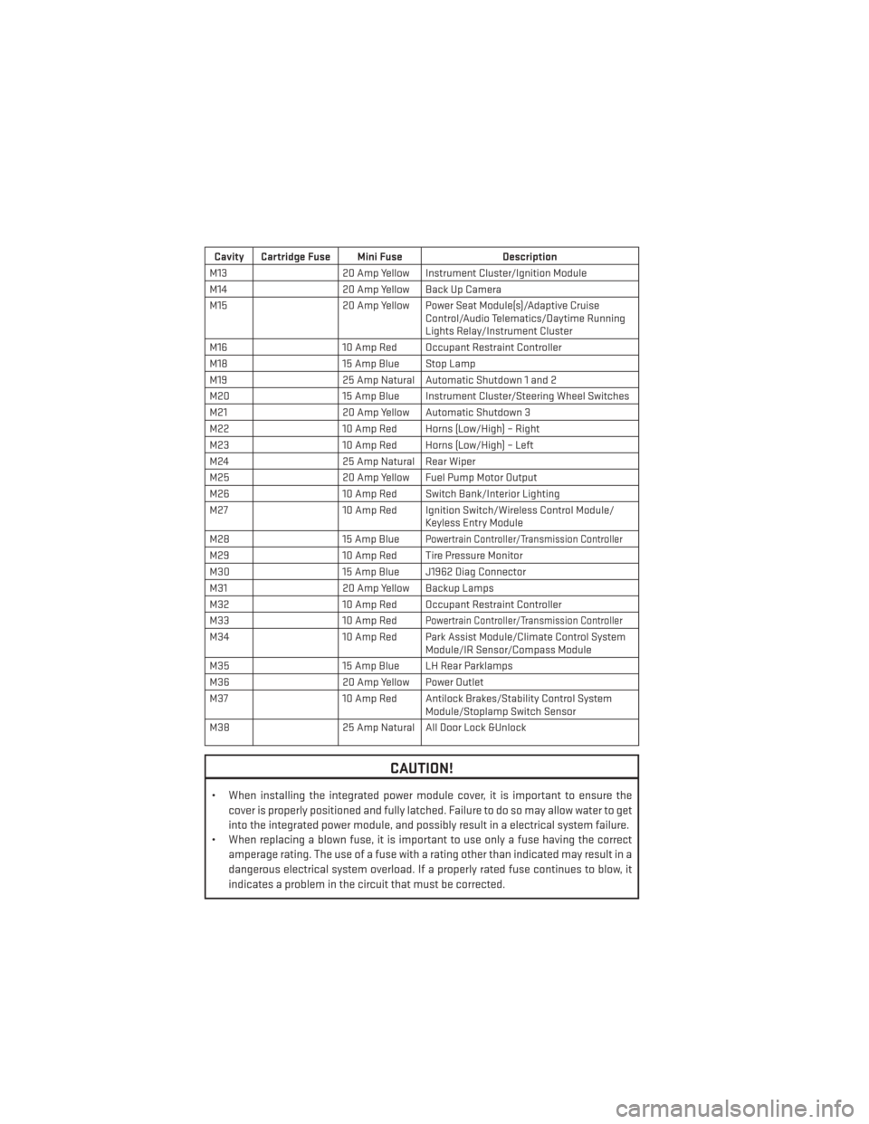
Cavity Cartridge Fuse Mini FuseDescription
M13 20 Amp Yellow Instrument Cluster/Ignition Module
M14 20 Amp Yellow Back Up Camera
M15 20 Amp Yellow Power Seat Module(s)/Adaptive Cruise
Control/Audio Telematics/Daytime Running
Lights Relay/Instrument Cluster
M16 10 Amp Red Occupant Restraint Controller
M18 15 Amp Blue Stop Lamp
M19 25 Amp Natural Automatic Shutdown 1 and 2
M20 15 Amp Blue Instrument Cluster/Steering Wheel Switches
M21 20 Amp Yellow Automatic Shutdown 3
M22 10 Amp Red Horns (Low/High) – Right
M23 10 Amp Red Horns (Low/High) – Left
M24 25 Amp Natural Rear Wiper
M25 20 Amp Yellow Fuel Pump Motor Output
M26 10 Amp Red Switch Bank/Interior Lighting
M27 10 Amp Red Ignition Switch/Wireless Control Module/
Keyless Entry Module
M28 15 Amp Blue
Powertrain Controller/Transmission Controller
M2910 Amp Red Tire Pressure Monitor
M30 15 Amp Blue J1962 Diag Connector
M31 20 Amp Yellow Backup Lamps
M32 10 Amp Red Occupant Restraint Controller
M33 10 Amp Red
Powertrain Controller/Transmission Controller
M3410 Amp Red Park Assist Module/Climate Control System
Module/IR Sensor/Compass Module
M35 15 Amp Blue LH Rear Parklamps
M36 20 Amp Yellow Power Outlet
M37 10 Amp Red Antilock Brakes/Stability Control System
Module/Stoplamp Switch Sensor
M38 25 Amp Natural All Door Lock &Unlock
CAUTION!
• When installing the integrated power module cover, it is important to ensure the
cover is properly positioned and fully latched. Failure to do so may allow water to get
into the integrated power module, and possibly result in a electrical system failure.
• When replacing a blown fuse, it is important to use only a fuse having the correct
amperage rating. The use of a fuse with a rating other than indicated may result in a
dangerous electrical system overload. If a properly rated fuse continues to blow, it
indicates a problem in the circuit that must be corrected.
MAINTAINING YOUR VEHICLE
126