tow DODGE DURANGO 2014 3.G User Guide
[x] Cancel search | Manufacturer: DODGE, Model Year: 2014, Model line: DURANGO, Model: DODGE DURANGO 2014 3.GPages: 664, PDF Size: 4.79 MB
Page 144 of 664
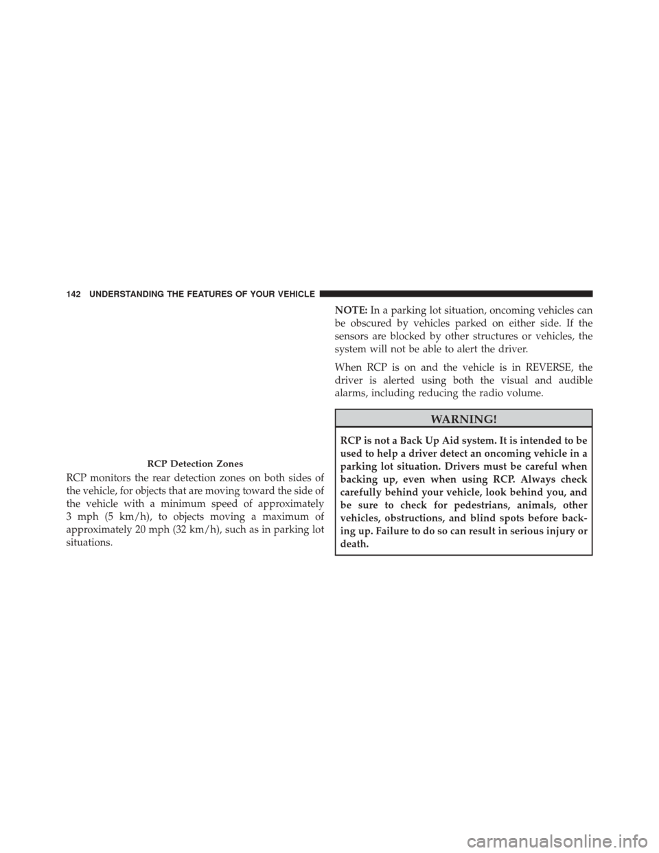
RCP monitors the rear detection zones on both sides of
the vehicle, for objects that are moving toward the side of
the vehicle with a minimum speed of approximately
3 mph (5 km/h), to objects moving a maximum of
approximately 20 mph (32 km/h), such as in parking lot
situations.NOTE:
In a parking lot situation, oncoming vehicles can
be obscured by vehicles parked on either side. If the
sensors are blocked by other structures or vehicles, the
system will not be able to alert the driver.
When RCP is on and the vehicle is in REVERSE, the
driver is alerted using both the visual and audible
alarms, including reducing the radio volume.
WARNING!
RCP is not a Back Up Aid system. It is intended to be
used to help a driver detect an oncoming vehicle in a
parking lot situation. Drivers must be careful when
backing up, even when using RCP. Always check
carefully behind your vehicle, look behind you, and
be sure to check for pedestrians, animals, other
vehicles, obstructions, and blind spots before back-
ing up. Failure to do so can result in serious injury or
death.
RCP Detection Zones
142 UNDERSTANDING THE FEATURES OF YOUR VEHICLE
Page 169 of 664
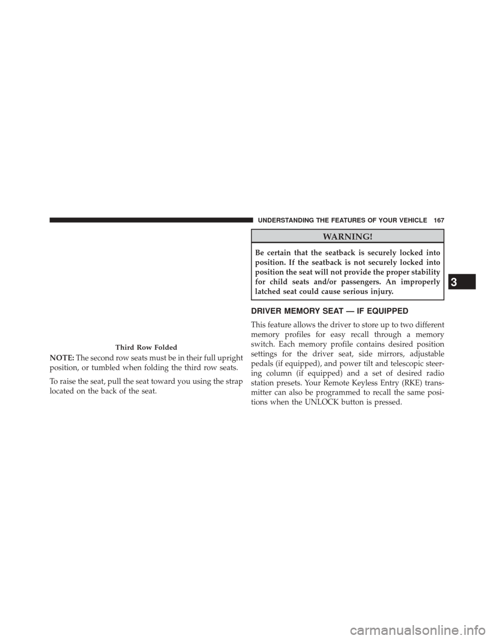
NOTE:The second row seats must be in their full upright
position, or tumbled when folding the third row seats.
To raise the seat, pull the seat toward you using the strap
located on the back of the seat.
WARNING!
Be certain that the seatback is securely locked into
position. If the seatback is not securely locked into
position the seat will not provide the proper stability
for child seats and/or passengers. An improperly
latched seat could cause serious injury.
DRIVER MEMORY SEAT — IF EQUIPPED
This feature allows the driver to store up to two different
memory profiles for easy recall through a memory
switch. Each memory profile contains desired position
settings for the driver seat, side mirrors, adjustable
pedals (if equipped), and power tilt and telescopic steer-
ing column (if equipped) and a set of desired radio
station presets. Your Remote Keyless Entry (RKE) trans-
mitter can also be programmed to recall the same posi-
tions when the UNLOCK button is pressed.
Third Row Folded
3
UNDERSTANDING THE FEATURES OF YOUR VEHICLE 167
Page 180 of 664
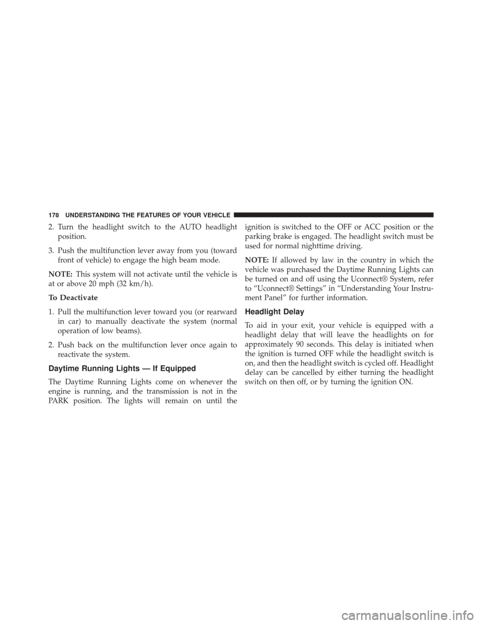
2. Turn the headlight switch to the AUTO headlightposition.
3. Push the multifunction lever away from you (toward front of vehicle) to engage the high beam mode.
NOTE: This system will not activate until the vehicle is
at or above 20 mph (32 km/h).
To Deactivate
1. Pull the multifunction lever toward you (or rearward in car) to manually deactivate the system (normal
operation of low beams).
2. Push back on the multifunction lever once again to reactivate the system.
Daytime Running Lights — If Equipped
The Daytime Running Lights come on whenever the
engine is running, and the transmission is not in the
PARK position. The lights will remain on until the ignition is switched to the OFF or ACC position or the
parking brake is engaged. The headlight switch must be
used for normal nighttime driving.
NOTE:
If allowed by law in the country in which the
vehicle was purchased the Daytime Running Lights can
be turned on and off using the Uconnect® System, refer
to “Uconnect® Settings” in “Understanding Your Instru-
ment Panel” for further information.
Headlight Delay
To aid in your exit, your vehicle is equipped with a
headlight delay that will leave the headlights on for
approximately 90 seconds. This delay is initiated when
the ignition is turned OFF while the headlight switch is
on, and then the headlight switch is cycled off. Headlight
delay can be cancelled by either turning the headlight
switch on then off, or by turning the ignition ON.
178 UNDERSTANDING THE FEATURES OF YOUR VEHICLE
Page 187 of 664
Lane Change Assist
Tap the lever up or down once, without moving beyond
the detent, and the turn signal (right or left) will flash
three times then automatically turn off.
Flash-To-Pass
You can signal another vehicle with your headlights by
partially pulling the multifunction lever toward the steer-
ing wheel. This will cause the high beam headlights to
turn on until the lever is released.
High/Low Beam Switch
Push the multifunction lever toward the instrument
panel to switch the headlights to high beam. Pulling the
multifunction back toward the steering wheel will turn
the low beams back on, or shut the high beams off.
WINDSHIELD WIPERS AND WASHERS
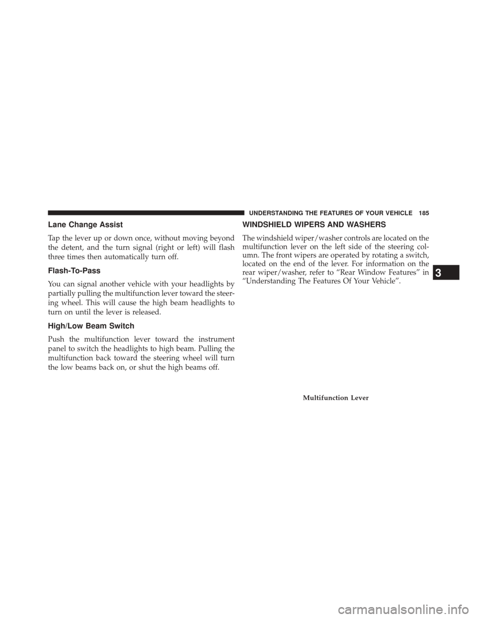
The windshield wiper/washer controls are located on the
multifunction lever on the left side of the steering col-
umn. The front wipers are operated by rotating a switch,
located on the end of the lever. For information on the
rear wiper/washer, refer to “Rear Window Features” in
“Understanding The Features Of Your Vehicle”.
Multifunction Lever
3
UNDERSTANDING THE FEATURES OF YOUR VEHICLE 185
Page 189 of 664
NOTE:If the vehicle is moving less than 10 mph
(16 km/h), delay times will be doubled.
Windshield Washer Operation
To use the washer, push on the end of the lever (toward
the steering wheel) and hold while spray is desired. If the lever is pushed while in the intermittent setting, the
wipers will turn on and operate for several wipe cycles
after the end of the lever is released, and then resume the
intermittent interval previously selected.
Intermittent Wiper Operation
Windshield Washer Operation
3
UNDERSTANDING THE FEATURES OF YOUR VEHICLE 187
Page 193 of 664
To unlock the steering column, push the lever downward
(toward the floor). To tilt the steering column, move the
steering wheel upward or downward as desired. To
lengthen or shorten the steering column, pull the steering
wheel outward or push it inward as desired. To lock the
steering column in position, push the lever upward until
fully engaged.
WARNING!
Do not adjust the steering column while driving.
Adjusting the steering column while driving or driv-
ing with the steering column unlocked, could cause
the driver to lose control of the vehicle. Failure to
follow this warning may result in serious injury or
death.
POWER TILT/TELESCOPING STEERING COLUMN
— IF EQUIPPED
This feature allows you to tilt the steering column
upward or downward. It also allows you to lengthen or
shorten the steering column. The power tilt/telescoping
steering column lever is located below the multifunction
lever on the steering column.
3
UNDERSTANDING THE FEATURES OF YOUR VEHICLE 191
Page 194 of 664
To tilt the steering column, move the lever up or down as
desired. To lengthen or shorten the steering column, pull
the lever toward you or push the lever away from you as
desired.NOTE:
For vehicles equipped with Driver Memory Seat,
you can use your Remote Keyless Entry (RKE) transmit-
ter or the memory switch on the driver’s door trim panel
to return the tilt/telescopic steering column to pre-
programmed positions. Refer to “Driver Memory Seat”
in this section for further information.
WARNING!
Do not adjust the steering column while driving.
Adjusting the steering column while driving or driv-
ing with the steering column unlocked, could cause
the driver to lose control of the vehicle. Failure to
follow this warning may result in serious injury or
death.
Power Tilt/Telescoping Steering Column
192 UNDERSTANDING THE FEATURES OF YOUR VEHICLE
Page 202 of 664
WARNING!(Continued)
•When driving in fog, heavy rain, heavy snow, sleet,
heavy traffic, and complex driving situations (i.e.,
in highway construction zones).
• When entering a turn lane or highway off ramp;
when driving on roads that are winding, icy, snow-
covered, slippery, or have steep uphill or downhill
slopes.
• When towing a trailer up or down steep slopes.
• When circumstances do not allow safe driving at a
constant speed. The Cruise Control system has two control modes:
•
Adaptive Cruise Control mode for maintaining an
appropriate distance between vehicles.
• Normal (fixed speed) electronic speed control mode
for cruising at a constant preset speed. For additional
information, refer to “Normal (Fixed Speed) Cruise
Control Mode” in this section.
NOTE: Normal (fixed speed) electronic speed control
will not react to preceding vehicles. Always be aware of
the mode selected.
You can change the mode by using the Cruise Control
buttons. The two control modes function differently.
Always confirm which mode is selected.
200 UNDERSTANDING THE FEATURES OF YOUR VEHICLE
Page 219 of 664
When the condition that created limited functionality is
no longer present, the system will return to full function-
ality.
NOTE:If the “ACC/FCW Limited Functionality Clean
Front Windshield” message occurs frequently (e.g. more
than once on every trip) without any snow, rain, mud, or
other obstruction, have the windshield and forward
facing camera inspected at your authorized dealer.
Service ACC/FCW Warning
If the system turns off, and the EVIC displays “ACC/
FCW Unavailable Service Required”or “Cruise/FCW
Unavailable Service Required”, there may be an internal
system fault or a temporary malfunction that limits ACC
functionality. Although the vehicle is still drivable under
normal conditions, ACC will be temporarily unavailable.
If this occurs, try activating ACC again later, following a
key cycle. If the problem persists, see your authorized
dealer.
Precautions While Driving With ACC
In certain driving situations, ACC may have detection
issues. In these cases, ACC may brake late or unexpect-
edly. The driver needs to stay alert and may need to
intervene.
Towing A Trailer
NOTE: Towing a trailer is not advised when using ACC.
3
UNDERSTANDING THE FEATURES OF YOUR VEHICLE 217
Page 240 of 664
WARNING!
•Drivers must be careful when backing up even
when using ParkSense®. Always check carefully
behind your vehicle, look behind you, and be sure
to check for pedestrians, animals, other vehicles,
obstructions, and blind spots before backing up.
You are responsible for safety and must continue to
pay attention to your surroundings. Failure to do so
can result in serious injury or death.
(Continued)
WARNING! (Continued)
•Before using ParkSense®, it is strongly recom-
mended that the ball mount and hitch ball assem-
bly is disconnected from the vehicle when the
vehicle is not used for towing. Failure to do so can
result in injury or damage to vehicles or obstacles
because the hitch ball will be much closer to the
obstacle than the rear fascia when the loudspeaker
sounds the continuous tone. Also, the sensors
could detect the ball mount and hitch ball assem-
bly, depending on its size and shape, giving a false
indication that an obstacle is behind the vehicle.
238 UNDERSTANDING THE FEATURES OF YOUR VEHICLE