air condition DODGE DURANGO 2014 3.G User Guide
[x] Cancel search | Manufacturer: DODGE, Model Year: 2014, Model line: DURANGO, Model: DODGE DURANGO 2014 3.GPages: 188, PDF Size: 3.8 MB
Page 45 of 188
• Press the AUTO button or AUTO soft-key.
• Select the desired temperature by pushing the up or down temperature buttons for thedriver or passenger.
• The system will maintain the set temperature automatically.
Air Conditioning (A/C)
• If the air conditioning button is pressed while in AUTO mode, the system will exit AUTO mode and stay in A/C. The mode and blower will be set at the closest mode and blower
position that the system was operating in AUTO.
MAX A/C
• MAX A/C sets the control for maximum cooling performance.
• Touch and release to toggle between MAX A/C and the prior settings. The soft-key illuminates when MAX A/C is ON.
• In MAX A/C, the blower level and mode position can be adjusted to desired user settings. Pressing other settings will cause the MAX A/C operation to switch to the prior settings
and the MAX A/C indicator will turn off.
SYNC Temperature Soft-Key
• Touch the “SYNC” soft-key on the Uconnect® radio to control the driver and passengertemperatures simultaneously. Touch the “SYNC” soft-key a second time to control the
temperatures individually.
Air Recirculation
• Use Recirculation for maximum A/C operation.
• For window defogging, turn the Recirculation button off.
• If the Recirculation button is pressed while in front defrost mode, the indicator will flashthree times to indicate that recirculation state is not allowed in front defrost mode.
Heated Mirrors
The mirrors are heated to melt frost or ice. This feature is activated whenever you turn on
the rear window defroster.
OPERATING YOUR VEHICLE
43
Page 64 of 188
Sample Commands For Voice Text Reply And Voice Texting
Example CommandAction
“Text John Smith” Send a message to specific contact in
address book
“Text 123 - 456 - 7890” Send 123 - 456 - 7890 a message from your
phonebook
“Show messages” See recent text messages listed by number
on Uconnect® screen
“Listen to/view (message number four, for example)” Hear messages or read it on
Uconnect® screen
“Reply” Send a voice text reply to a current message
“Forward text/message to “John Smith” Forward current text to specific contact in
address book
“Forward text/message to “123 - 456 - 7890” Forward current text to specific
phone number
Uconnect® Access Via Mobile (If Equipped — Available On
Uconnect® 8.4A And Uconnect® 8.4AN)
Uconnect® Access via Mobile offers additional apps such as Aha™, iHeartRadio, Pandora®
and Slacker Radio. It uses your smartphone’s existing data plan to access Uconnect®
System-enabled apps, which you can control using both your touchscreen and steering
wheel controls. Customer’s data plan charges will apply.
To get started using Via Mobile apps, first register your Uconnect® Access system where
you'll be guided through the setup of your Via Mobile (requires a compatible Android or
iPhone® smartphone). Please refer to “Uconnect® Access Registration” for more informa-
tion.
The Uconnect® Access app is compatible with select iPhone® and Android smartphones.
Visit UconnectPhone.com to confirm that your smartphone is compatible with Uconnect®.
Once you’ve confirmed your smartphone is compatible, pair it to the vehicle touchscreen
via Bluetooth® to use Via Mobile apps. If using an iPhone®, a USB cable may also be
supported for the data connection.
Launch the Uconnect® Access App on your smartphone, and login with your username and
password that was set up during registration. Accept the Terms and Conditions.
ELECTRONICS
62
Page 134 of 188
When the malfunction indicator is illuminated, the system may not be able to detect or
signal low tire pressure as intended. TPMS malfunctions may occur for a variety of reasons,
including the installation of replacement or alternate tires or wheels on the vehicle that
prevent the TPMS from functioning properly. Always check the TPMS malfunction telltale
after replacing one or more tires or wheels on your vehicle, to ensure that the replacement
or alternate tires and wheels allow the TPMS to continue to function properly.
NOTE:
Tire pressures change by approximately 1 psi (7 kPa) per 12° F (7° C) of air temperature
change. Keep this in mind when checking tire pressure inside a garage, especially in the
Winter. Example: If garage temperature is 68°F (20°C) and the outside temperature is 32°F
(0°C), then the cold tire inflation pressure should be increased by 3 psi (21 kPa), which equals
1 psi (7 kPa) for every 12°F (7°C) for this outside temperature condition.
CAUTION!
The TPMS has been optimized for the original equipment tires and wheels. TPMS
pressures and warning have been established for the tire size equipped on your vehicle.
Undesirable system operation or sensor damage may result when using replacement
equipment that is not of the same size, type, and/or style. Aftermarket wheels can cause
sensor damage. Do not use tire sealant from a can, or balance beads if your vehicle is
equipped with a TPMS, as damage to the sensors may result.
BRAKE- Brake Warning Light
This light monitors various brake functions, including brake fluid level and parking brake
application. If the brake light turns on it may indicate that the parking brake is applied, that the
brake fluid level is low, or that there is a problem with the anti-lock brake system reservoir.
If the light remains on when the parking brake has been disengaged, and the fluid level is at
the full mark on the master cylinder reservoir, it indicates a possible brake hydraulic system
malfunction or that a problem with the Brake Booster has been detected by the Anti-Lock
Brake System (ABS)/Electronic Stability Control (ESC) system. In this case, the light will
remain on until the condition has been corrected. If the problem is related to the brake
booster, the ABS pump will run when applying the brake and a brake pedal pulsation may be
felt during each stop.
The dual brake system provides a reserve braking capacity in the event of a failure to a
portion of the hydraulic system. A leak in either half of the dual brake system is indicated by
the Brake Warning Light, which will turn on when the brake fluid level in the master cylinder
has dropped below a specified level. The light will remain on until the cause is corrected.
Vehicles equipped with the Anti-Lock Brake System (ABS), are also equipped with Electronic
Brake Force Distribution (EBD). In the event of an EBD failure, the Brake Warning Light will
turn on along with the ABS Light. Immediate repair to the ABS system is required.
WHAT TO DO IN EMERGENCIES
132
Page 139 of 188
IF YOUR ENGINE OVERHEATS
In any of the following situations, you can reduce the potential for overheating by taking the
appropriate action:
• On the highways — slow down.
• In city traffic — while stopped, shift the transmission to NEUTRAL, but do not increaseengine idle speed.
NOTE:
There are steps that you can take to slow down an impending overheat condition:
• If your air conditioner (A/C) is on, turn it off. The A/C system adds heat to the engine cooling system and turning the A/C off can help remove this heat.
• You can also turn the temperature control to maximum heat, the mode control to floor and the blower control to high. This allows the heater core to act as a supplement to the
radiator and aids in removing heat from the engine cooling system.
CAUTION!
Driving with a hot cooling system could damage your vehicle. If the temperature gauge
reads HOT (H), pull over and stop the vehicle. Idle the vehicle with the air conditioner
turned off until the pointer drops back into the normal range. If the pointer remains on
HOT (H), and you hear continuous chimes, turn the engine off immediately, and call for
service.
WARNING!
You or others can be badly burned by hot engine coolant (antifreeze) or steam from your
radiator. If you see or hear steam coming from under the hood, do not open the hood until
the radiator has had time to cool. Never try to open a cooling system pressure cap when
the radiator or coolant bottle is hot.
WHAT TO DO IN EMERGENCIES
137
Page 155 of 188
EVENT DATA RECORDER (EDR)
This vehicle is equipped with an Event Data Recorder (EDR). The main purpose of an EDR is
to record, in certain crash or near crash-like situations, such as an air bag deployment or
hitting a road obstacle, data that will assist in understanding how a vehicle’s systems
performed. The EDR is designed to record data related to vehicle dynamics and safety
systems for a short period of time, typically 30 seconds or less. The EDR in this vehicle is
designed to record such data as:
• How various systems in your vehicle were operating.
• Whether or not the driver and passenger safety belts were buckled/fastened.
• How far (if at all) the driver was depressing the accelerator and/or brake pedal.
• How fast the vehicle was traveling.
These data can help provide a better understanding of the circumstances in which crashes
and injuries occur.
NOTE:
EDR data is recorded by your vehicle only if a non-trivial crash situation occurs; no data is
recorded by the EDR under normal driving conditions and no personal data (e.g. name,
gender, age, and crash location) is recorded. However, other parties, such as law enforce-
ment, could combine the EDR data with the type of personally identifying data routinely
acquired during a crash investigation.
To read data recorded by an EDR, special equipment is required, and access to the vehicle or
the EDR is needed. In addition to the vehicle manufacturer, other parties such as law enforce-
ment, that have the special equipment, can read the information if they have access to the
vehicle or the EDR.
CAP-LESS FUEL FILL FUNNEL
The funnel for the Cap-Less Fuel System is located on the jacking tool kit. If your vehicle is
out of fuel and an auxiliary fuel can is needed, insert the funnel into the filler neck and
proceed to fill the vehicle.
WHAT TO DO IN EMERGENCIES
153
Page 163 of 188
MAINTENANCE SCHEDULE — GASOLINE ENGINE
Your vehicle is equipped with an automatic oil change indicator system. The oil change indicator
system will remind you that it is time to take your vehicle in for scheduled maintenance.
Based on engine operation conditions, the oil change indicator message will illuminate. This
means that service is required for your vehicle. Operating conditions such as frequent short-
trips, trailer tow, extremely hot or cold ambient temperatures, and E85 fuel usage will influence
when the “Oil Change Required” message is displayed. Severe Operating Conditions can cause
the change oil message to illuminate as early as 3,500 miles (5,600 km) since last reset. Have
your vehicle serviced as soon as possible, within the next 500 miles (805 km).
Your authorized dealer will reset the oil change indicator message after completing the
scheduled oil change. If a scheduled oil change is performed by someone other than your
authorized dealer, the message can be reset by referring to the steps described under “Instru-
ment Cluster Warning Lights” in “What To Do In Emergencies” in this guide or “Electronic
Vehicle Information Center (EVIC)” in “Understanding Your Instrument Panel” in your Owners
Manual on the DVD for further information.
NOTE:
Under no circumstances should oil change intervals exceed 10,000 miles (16,000 km) or
twelve months, whichever comes first.
Severe Duty All Models
Change Engine Oil at 4000 miles (6,500 km) if the vehicle is operated in a dusty and off road
environment. This type of vehicle use is considered Severe Duty.
Once A Month Or Before A Long Trip:
• Check engine oil level
• Check windshield washer fluid level
• Check the tire inflation pressures and look for unusual wear or damage
• Check the fluid levels of the coolant reservoir, brake master cylinder, power steering andtransmission as needed
• Check function of all interior and exterior lights
Required Maintenance
Refer to the Maintenance Schedules on the following pages for required maintenance.
At Every Oil Change Interval As Indicated By Oil Change Indicator System:
• Change oil and filter.
• Rotate the tires. Rotate at the first sign of irregular wear, even if it occurs before the oil
indicator system turns on.
• Inspect battery and clean and tighten terminals as required.
• Inspect automatic transmission fluid if equipped with dipstick.
• Inspect brake pads, shoes, rotors, drums, hoses and park brake.
• Inspect engine cooling system protection and hoses.
• Inspect exhaust system.
• Inspect engine air cleaner if using in dusty or off-road conditions.
MAINTAINING YOUR VEHICLE
161
Page 164 of 188
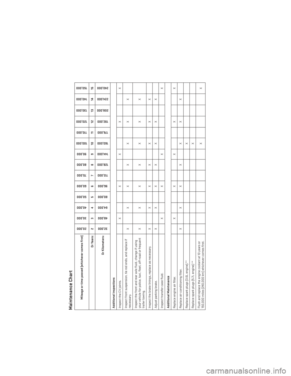
Maintenance Chart
Mileage or time passed (whichever comes first)
20,00030,000
40,000
50,000
60,000 70,000
80,000 90,000
100,000
110,000
120,000
130,000
140,000
150,000
Or Years: 2 3 4 5 6 7 8 9 10 11 12 13 14 15
Or Kilometers:
32,000
48,000
64,000
80,000
96,000
112,000
128,000 144,000
160,000
176,000
192,000
208,000 224,000
240,000
Additional Inspections
Inspect the CV joints. X X X X X
Inspect front suspension, tie rod ends, and replace if
necessary. XX X XX X X
Inspect the front and rear axle fluid, change if using
your vehicle for police, taxi, fleet, off-road or frequent
trailer towing. XX X XX X X
Inspect the brake linings, replace as necessary. X X X X X X X
Adjust parking brake. X X X X X X X
Inspect transfer case fluid. X X X X
Additional Maintenance
Replace engine air filter. X X X X X
Replace air conditioning filter. X X X X X X X
Replace spark plugs (3.6L engine).** X
Replace spark plugs (5.7L engine).** X
Flush and replace the engine coolant at 10 years or
150,000 miles (240,000 km) whichever comes first. XX
MAINTAINING YOUR VEHICLE
162
Page 168 of 188
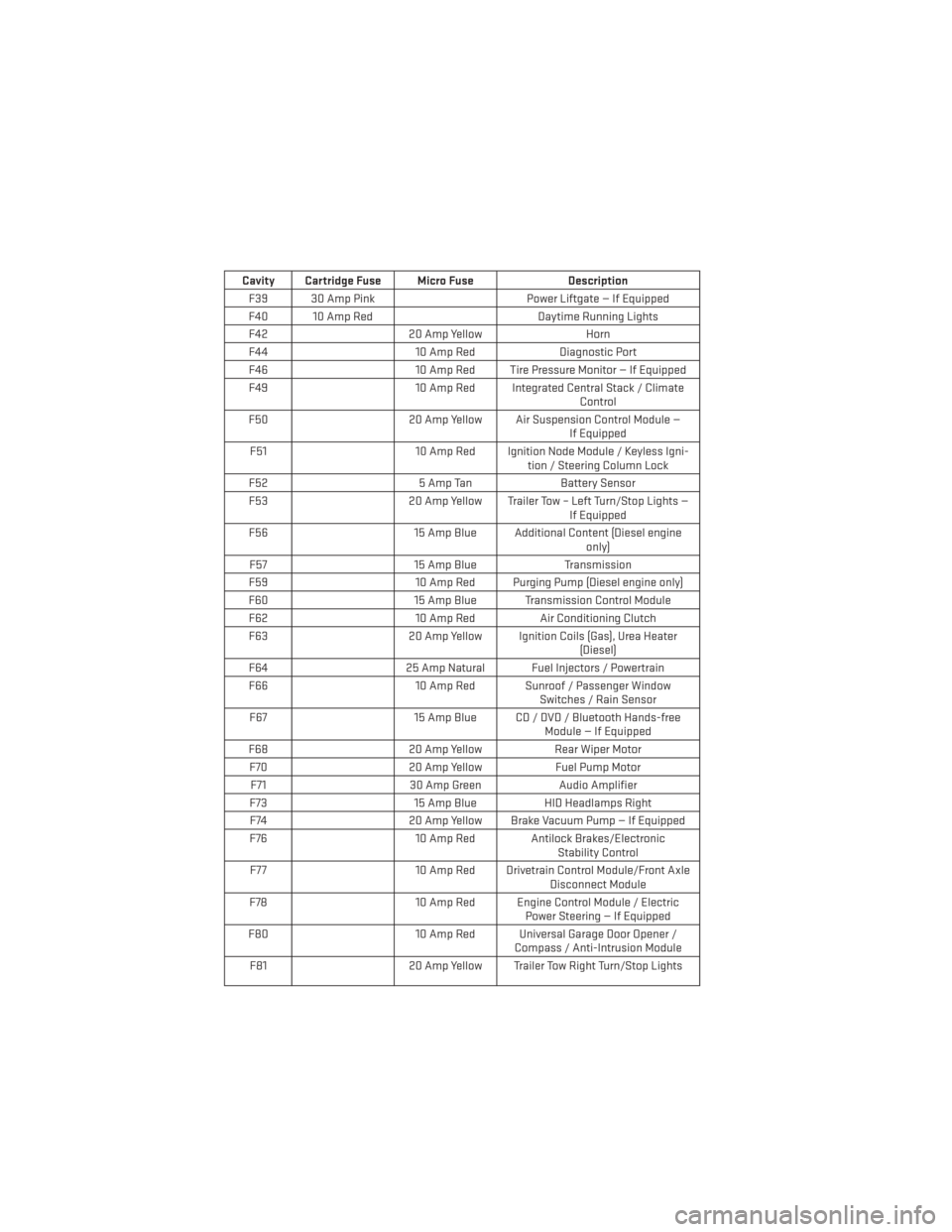
Cavity Cartridge Fuse Micro FuseDescription
F39 30 Amp Pink Power Liftgate — If Equipped
F40 10 Amp Red Daytime Running Lights
F42 20 Amp Yellow Horn
F44 10 Amp RedDiagnostic Port
F46 10 Amp Red Tire Pressure Monitor — If Equipped
F49 10 Amp Red Integrated Central Stack / Climate
Control
F50 20 Amp Yellow Air Suspension Control Module —
If Equipped
F51 10 Amp Red Ignition Node Module / Keyless Igni-
tion / Steering Column Lock
F52 5 Amp TanBattery Sensor
F53 20 Amp Yellow Trailer Tow – Left Turn/Stop Lights —
If Equipped
F56 15 Amp Blue Additional Content (Diesel engine
only)
F57 15 Amp BlueTransmission
F59 10 Amp Red Purging Pump (Diesel engine only)
F60 15 Amp Blue Transmission Control Module
F62 10 Amp RedAir Conditioning Clutch
F63 20 Amp Yellow Ignition Coils (Gas), Urea Heater
(Diesel)
F64 25 Amp Natural Fuel Injectors / Powertrain
F66 10 Amp Red Sunroof / Passenger Window
Switches / Rain Sensor
F67 15 Amp Blue CD / DVD / Bluetooth Hands-free
Module — If Equipped
F68 20 Amp YellowRear Wiper Motor
F70 20 Amp YellowFuel Pump Motor
F71 30 Amp GreenAudio Amplifier
F73 15 Amp BlueHID Headlamps Right
F74 20 Amp Yellow Brake Vacuum Pump — If Equipped
F76 10 Amp Red Antilock Brakes/Electronic
Stability Control
F77 10 Amp Red Drivetrain Control Module/Front Axle
Disconnect Module
F78 10 Amp Red Engine Control Module / Electric
Power Steering — If Equipped
F80 10 Amp Red Universal Garage Door Opener /
Compass / Anti-Intrusion Module
F81 20 Amp Yellow Trailer Tow Right Turn/Stop Lights
MAINTAINING YOUR VEHICLE
166
Page 177 of 188
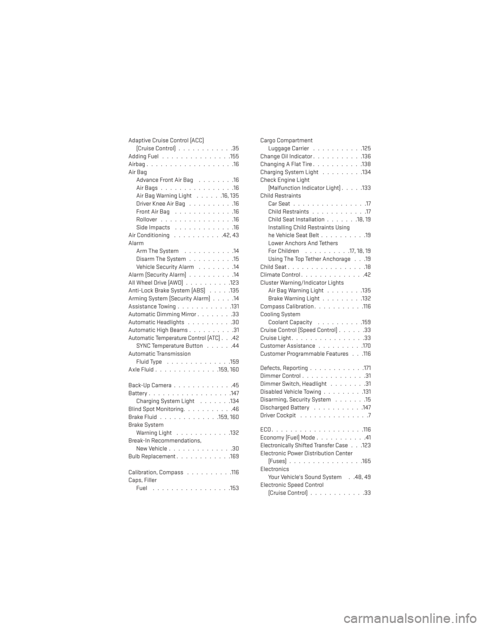
Adaptive Cruise Control (ACC)(Cruise Control) ............35
AddingFuel ...............155
Airbag...................16
Air Bag AdvanceFrontAirBag ........16
AirBags................16
AirBagWarningLight ......16,135
Driver Knee Air Bag ..........16
FrontAirBag .............16
Rollover ................16
Side Impacts .............16
Air Conditioning ...........42,43
Alarm Arm The System ...........14
Disarm The System ..........15
Vehicle Security Alarm ........14
Alarm (Security Alarm) ..........14
AllWheelDrive(AWD)..........123
Anti-Lock Brake System (ABS) .....135
Arming System (Security Alarm) .....14
Assistance Towing ............131
Automatic Dimming Mirror ........33
Automatic Headlights ..........30
Automatic High Beams ..........31
Automatic Temperature Control (ATC)...42
SYNC Temperature Button ......44
Automatic Transmission Fluid Type ..............159
AxleFluid..............159,160
Back-UpCamera.............45
Battery ..................147
Charging System Light .......134
Blind Spot Monitoring ...........46
BrakeFluid.............159,160
Brake System WarningLight ............132
Break-In Recommendations, New Vehicle ..............30
BulbReplacement............169
Calibration, Compass ..........116
Caps, Filler Fuel .................153 Cargo Compartment
Luggage Carrier ...........125
Change Oil Indicator ...........136
ChangingAFlatTire...........138
Charging System Light .........134
Check Engine Light (Malfunction Indicator Light) .....133
Child Restraints CarSeat................17
Child Restraints ............17
Child Seat Installation .......18,19
Installing Child Restraints Using
he Vehicle Seat Belt ..........19
Lower Anchors And Tethers
For Children ..........17, 18, 19
Using The Top Tether Anchorage . . .19
ChildSeat.................18
Climate Control ..............42
Cluster Warning/Indicator Lights AirBagWarningLight ........135
Brake Warning Light .........132
Compass Calibration ...........116
Cooling System Coolant Capacity ..........159
Cruise Control (Speed Control) ......33
Cruise Light ................33
Customer Assistance ..........170
Customer Programmable Features . . .116
Defects, Reporting ............171
DimmerControl..............31
Dimmer Switch, Headlight ........31
Disabled Vehicle Towing .........131
Disarming, Security System .......15
Discharged Battery ...........147
Driver Cockpit ...............7
ECO....................116
Economy (Fuel) Mode ...........41
Electronically Shifted Transfer Case. . .123
Electronic Power Distribution Center (Fuses) ................165
Electronics Your Vehicle's Sound System . .48, 49
Electronic Speed Control (Cruise Control) ............33
INDEX
175