park assist DODGE DURANGO 2014 3.G User Guide
[x] Cancel search | Manufacturer: DODGE, Model Year: 2014, Model line: DURANGO, Model: DODGE DURANGO 2014 3.GPages: 188, PDF Size: 3.8 MB
Page 3 of 188
INTRODUCTION/WELCOME
WELCOME FROM CHRYSLER GROUP LLC . . . 2
CONTROLS AT A GLANCE
DRIVER COCKPIT................6
INSTRUMENT CLUSTER .............8
GETTING STARTED
KEYFOB ....................10
REMOTE START.................11
KEYLESS ENTER-N-GO™ ............11
VEHICLE SECURITY ALARM ..........14
SEATBELT ...................15
SUPPLEMENTAL RESTRAINT SYSTEM (SRS) —
AIRBAGS ....................16
CHILD RESTRAINTS ..............17
FRONT SEATS ..................21
REARSEATS ..................24
POWER FOLDING THIRD ROW HEAD
RESTRAINTS ..................26
HEATED/VENTILATED SEATS .........26
HEATED STEERING WHEEL ..........28
TILT/TELESCOPING STEERING COLUMN . . . 29
OPERATING YOUR VEHICLE
ENGINE BREAK-IN RECOMMENDATIONS . . . 30
HEADLIGHT SWITCH ..............30
TURN SIGNAL/WIPER/WASHER/HIGH BEAM
LEVER ......................31
AUTOMATIC DIMMING MIRRORS .......33
SPEED CONTROL ................33
ADAPTIVE CRUISE CONTROL (ACC) ......35
FORWARD COLLISION WARNING (FCW)
WITHMITIGATION ...............37
ELECTRONIC SHIFTER .............39
AUTOSTICK® ..................40
FUEL ECONOMY (ECO) MODE .........41
AUTOMATIC CLIMATE CONTROLS WITH
TOUCHSCREEN .................42
PARKSENSE® REAR PARK ASSIST ......45
PARKVIEW® REAR BACK-UP CAMERA ....45
BLIND SPOT MONITORING ...........46
POWER SUNROOF ...............46
WIND BUFFETING ................47
ELECTRONICS
YOUR VEHICLE'S SOUND SYSTEM ......48
IDENTIFYING YOUR RADIO ...........50
Uconnect® ACCESS ..............51
Uconnect® 5.0 .................66
Uconnect® 8.4A .................74
Uconnect® 8.4AN ...............94
STEERING WHEEL AUDIO CONTROLS ....115
ELECTRONIC VEHICLE INFORMATION
CENTER (EVIC) .................115
PROGRAMMABLE FEATURES .........116UNIVERSAL GARAGE DOOR OPENER
(HomeLink®)
..................118
POWER INVERTER ..............120
POWER OUTLET ................121
OFF-ROAD CAPABILITIES
ALL-WHEEL DRIVE OPERATION .......123
UTILITY
ROOF LUGGAGE RACK............125
TRAILER TOWING WEIGHTS
(MAXIMUM TRAILER WEIGHT RATINGS) . . 125
RECREATIONAL TOWING
(BEHIND MOTORHOME, ETC.) ........126
WHAT TO DO IN EMERGENCIES
ROADSIDE ASSISTANCE...........131INSTRUMENT CLUSTER WARNING LIGHTS . . . 131IF YOUR ENGINE OVERHEATS .........137
JACKING AND TIRE CHANGING .......138
BATTERY LOCATION ..............147
JUMP-STARTING ...............147
MANUAL PARK RELEASE 8-SPEED .....150
TOWING A DISABLED VEHICLE ........151
FREEING A STUCK VEHICLE .........152
EVENT DATA RECORDER (EDR) ........153
CAP-LESS FUEL FILL FUNNEL ........153
MAINTAINING YOUR VEHICLE
OPENING THE HOOD.............154
ADDING FUEL .................155
ENGINE COMPARTMENT ...........157
FLUIDS AND CAPACITIES ...........159
MAINTENANCE SCHEDULE —
GASOLINE ENGINE ...............161
MAINTENANCE RECORD ...........164
FUSES .....................165
TIRE PRESSURES ...............168
WHEEL AND WHEEL TRIM CARE ......169
EXTERIOR BULBS ..............169
CUSTOMER ASSISTANCE
CHRYSLER GROUP LLC
CUSTOMER CENTER .............170
CHRYSLER CANADA INC.
CUSTOMER CENTER .............170
ASSISTANCE FOR THE HEARING IMPAIRED..170
PUBLICATIONS ORDERING ..........170
REPORTING SAFETY DEFECTS IN THE
UNITEDSTATES ................171
MOPAR® ACCESSORIES
AUTHENTIC ACCESSORIES BY MOPAR® . . . 172
FREQUENTLY ASKED QUESTIONS
FREQUENTLY ASKED QUESTIONS ......173
INDEX....................175
TABLE OF CONTENTS
Page 33 of 188
Automatic High Beams
The Automatic High Beams system provides increased forward lighting at night by auto-
mating high beam control through the use of a digital camera mounted on the inside
rearview mirror. This camera detects vehicle specific light and automatically switches from
high beams to low beams until the approaching vehicle is out of view. This feature is
programmable through the Uconnect® system. Refer to “Uconnect® Settings ” in “Under-
standing Your Instrument Panel” in the Owner's Manual on the DVD for further details.
Instrument Panel Dimmer
• Rotate the dimmer control to the extreme bottom position to fully dim the instrumentpanel lights and prevent the interior lights from illuminating when a door is opened.
• Rotate the dimmer control up to increase the brightness of the instrument panel when the parking lights or headlights are on.
• Rotate the dimmer control up to the next detent position to fully brighten the odometer and radio when the parking lights or headlights are on.
• Rotate the dimmer control up to the last detent position to turn on the interior lighting.
• If your vehicle is equipped with a touchscreen, the dimming is programmable through the Uconnect® system. Refer to “Uconnect® Settings ” in “Understanding Your Instru-
ment Panel” in the Owner's Manual on the DVD for further details.
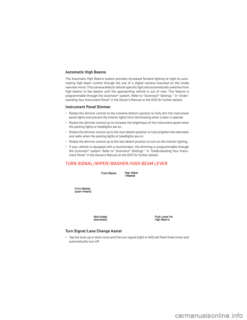
TURN SIGNAL/WIPER/WASHER/HIGH BEAM LEVER
Turn Signal/Lane Change Assist
• Tap the lever up or down once and the turn signal (right or left) will flash three times andautomatically turn off.
OPERATING YOUR VEHICLE
31
Page 47 of 188
PARKSENSE® REAR PARK ASSIST
The four ParkSense® sensors, located in the rear fascia/bumper, monitor the area behind
the vehicle that is within the sensors’ field of view.
The sensors can detect obstacles from approximately 12 in (30 cm) up to 79 in (200 cm)
from the rear bumper while the vehicle is in REVERSE, a warning will display in the Electronic
Vehicle Information Center (EVIC) and a chime will sound (when Sound and Display is
selected from the Customer Programmable Features section of the Uconnect® System
screen). As the vehicle moves closer to the object, the chime rate will change from single
1/2 second tone, to slow, to fast, to continuous.
Cleaning The ParkSense® Sensors
If “CLEAN PARK ASSIST SENSORS” appears in the Electronic Vehicle Information Center
(EVIC), clean the ParkSense® sensors with water, car wash soap and a soft cloth. Do not use
rough or hard cloths. Do not scratch or poke the sensors. Otherwise, you could damage the
sensors.
NOTE:
When the Instrument Cluster reads either Clean Sensor or Blinded, please clean off the
bumper sensors to see if the condition is corrected.
PARKVIEW® REAR BACK-UP CAMERA
You can see an on-screen image of the rear of your vehicle whenever the shift lever/gear
selector is put into REVERSE. The ParkView® Rear Back-Up Camera image will be displayed
on the radio display screen, located on the center stack of the instrument panel.
If the radio display screen appears foggy, clean the camera lens located on the liftgate.
WARNING!
Drivers must be careful when backing up; even when using the ParkView® Rear Back-Up
Camera. Always check carefully behind your vehicle, and be sure to check for pedestri-
ans, animals, other vehicles, obstructions, or blind spots before backing up. You must
continue to pay attention while backing up. Failure to do so can result in serious injury or
death.
OPERATING YOUR VEHICLE
45
Page 55 of 188
Uconnect® Access Registration (Uconnect® 8.4AN Only,
U.S. 48 Contiguous States And Alaska)
NOTE:
Should you require assistance anytime during the registration process, simply call Uconnect®
Care at 855-792-4241.
1. From the parked vehicle with the radio touchscreen powered on, select the “Apps” buttonon the touchscreen located near the bottom right-hand corner.
2. Press “Register” if you see a reminder screen or select “Uconnect Registration” under the 'Favorites' tab.
3. The Uconnect® Access Registration App will open and display step-by-step instructions to start your registration.
4. Enter your email address into the radio touchscreen.
5. A message will display on the touchscreen indicating your email submission was accepted.
6. At home, or wherever you access your email, look for an email from Uconnect® Access that contains your personalized registration link. If you don't see it, check your spam or
junk email folder. Open the email and click on the link to continue registering online.
NOTE:
For security reasons, this link is valid for 72 hours from the time you submit your email address
into the radio touchscreen. If the link has expired, start the process over (see step 1).
7. You are now registered for your Uconnect® Access Trial! Apps will be downloaded the next time you start your vehicle. It may take over 30 minutes for all of the Apps to
install. If the Apps have not appeared after 72 hours, please contact Uconnect® Care at
855-792-4241.
8. Get to know Uconnect® Access! We recommend:
• Go to moparownerconnect.com and log in using the email address and password youestablished while registering. Go to the Learn & Use tab for complete information on
using Uconnect® Access.
• If you have a smartphone, download the Uconnect® Access App and set up your Via Mobile features. See instructions below.
ELECTRONICS
53
Page 57 of 188
Purchasing Online
You can renew your subscription to a package or purchase WiFi from the Mopar Owner
Connect website. You must first set up a Uconnect® Access Payment Account online.
Log into moparownerconnect.com, select Edit Profile, then Uconnect® Payment Account.
1. Log In to the Mopar Owner Connect website (moparownerconnect.com) with yourusername/email and password.
2. Click on the “Shop” tab, then click on the Uconnect® Store.
3. From the Uconnect® Store, select the item you wish to purchase.
4.
This will launch the selected item into purchase mode along with providing additional
information. The purchase process begins when you press the “Buy” button on the touch-
screen.
5. The Uconnect® Store will display a “Purchase Overview” message confirming the finan- cial details of your purchase. Press the “Purchase” key to continue.
6. The Uconnect® Store will ask you to “Confirm Payment” using your default payment method on file in your Payment Account. Press the “Complete” key to continue.
7. The Uconnect® Payment Account will then ask for your “Payment Account PIN,” which you established when setting up your Uconnect® payment account. After entering this
four digit PIN, press the “Complete” key to make the purchase.
8. You will receive a confirmation message that your purchase has been submitted. Press the OK button to end the process.
Purchasing WiFi Hotspot While In Your Vehicle
You must set up a Uconnect® Access Payment Account online (log in to moparownerconnect.com,
go to Edit Profile, then Uconnect® Payment Account,to set up and manage your Payment Account).
1.To purchase WiFi while in your vehicle, ensure the vehicle is running and in Park. Press the
Apps button on the touchscreen, then select WiFi within the Tools menu. Follow the
on-screen instructions. When asked for your payment PIN, use the 4-digit PIN you estab-
lished when setting up your payment account on Mopar Owner Connect.
NOTE:
This may be different than the Uconnect® Security PIN you established for using features
such as Remote Vehicle Start. After purchasing WiFi, it may take up to 30 minutes (with the
vehicle running) before the WiFi will be active in your vehicle.
2. Select WiFi again, then note the hotspot name. Select this network when connecting
devices to the hotspot. Also click on View/Edit Passphrase, then note the security
passphrase you will need to connect to the network on each device.
If your devices cannot see the WiFi Hotspot network after 30 minutes, please contact
Uconnect® Care by pressing the Assist button on the rear view mirror, or by calling 855-792-4241.
ELECTRONICS
55
Page 120 of 188
UNIVERSAL GARAGE DOOR OPENER (HomeLink®)
•HomeLink® replaces up to three hand-held transmitters that operate devices such as
garage door openers, motorized gates, lighting or home security systems. The HomeLink®
unit is powered by your vehicles 12 Volt battery.
• The HomeLink® buttons that are located in the overhead console or sunvisor designate the three different HomeLink® channels.
• The HomeLink® indicator is located above the center button.
Before You Begin Programming HomeLink®
•Be sure that your vehicle is parked outside of
the garage before you begin programming.
•For more efficient programming and accu-
rate transmission of the radio-frequency
signal it is recommended that a new battery
be placed in the hand-held transmitter of
the device that is being programmed to the
HomeLink® system.
•Erase all channels before you begin pro-
gramming. To erase the channels, place
the ignition switch into the ON/RUN posi-
tion, then press and hold the two out-
side HomeLink® buttons (I and III) for up to
20 seconds or until the red indicator flashes.
NOTE:
• Erasing all channels should only be performed when programming HomeLink® for the
first time. Do not erase channels when programming additional buttons.
• If you have any problems, or require assistance, please call toll-free 1–800–355– 3515 or, on the Internet at www.HomeLink.com for information or assistance.
Programming A Rolling Code
NOTE:
For programming Garage Door Openers that were manufactured after 1995. These Garage Door
Openers can be identified by the “LEARN” or “TRAIN” button located where the hanging
antenna is attached to the Garage Door Opener. It is NOT the button that is normally used to
open and close the door. The name and color of the button may vary by manufacturer.
1. Place the ignition switch into the ON/RUN position.
2. Place the hand-held transmitter 1 to 3 in (3 to 8 cm) away from the HomeLink® button you
wish to program while keeping the HomeLink® indicator light in view.
3. Simultaneously press and hold both the HomeLink® button you want to program and the hand-held transmitter button.
ELECTRONICS
118
Page 149 of 188
BATTERY LOCATION
The battery in your vehicle is located under the passenger's front seat. Remote battery
posts are located on the right side of the engine compartment for jump-starting.
JUMP-STARTING
If your vehicle has a discharged battery it can be jump-started using a set of jumper cables
and a battery in another vehicle or by using a portable battery booster pack.
Jump-starting can be dangerous if done improperly so please follow the procedures in this
section carefully.
NOTE:
When using a portable battery booster pack follow the manufacturer’s operating instruc-
tions and precautions.
Preparations For Jump-Start
The battery in your vehicle is located under
the passengers front seat. There are remote
locations under the hood to assist in jump
starting.
• Set the parking brake, shift the automatictransmission into PARK and turn the igni-
tion to OFF.
• Turn off the heater, radio, and all unneces- sary electrical accessories.
• Remove the protective cover over the re- mote positive (+) battery post. Pull upward
on the cover to remove it.
• Remove the protective plug covering the remote negative (-) post.
• If using another vehicle to jump-start the battery, park the vehicle within the jumper
cables reach, set the parking brake and
make sure the ignition is OFF.
1 — Remote Positive (+) Jump Starting Post
2 — Remote Negative (-) Jump Starting Post
WHAT TO DO IN EMERGENCIES
147
Page 169 of 188
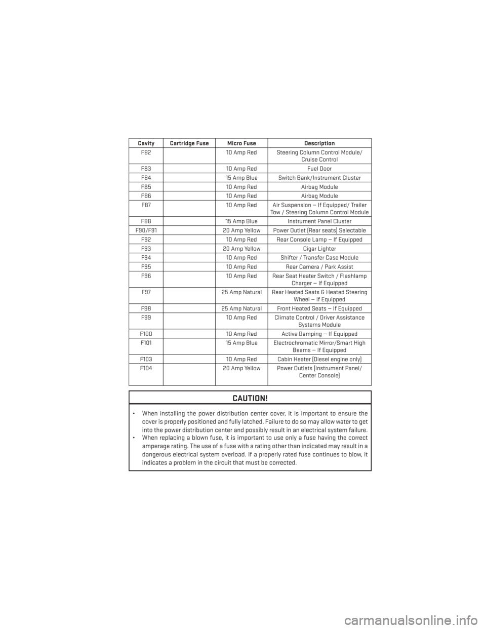
Cavity Cartridge Fuse Micro FuseDescription
F82 10 Amp Red Steering Column Control Module/
Cruise Control
F83 10 Amp RedFuel Door
F84 15 Amp Blue Switch Bank/Instrument Cluster
F85 10 Amp RedAirbag Module
F86 10 Amp RedAirbag Module
F87 10 Amp Red Air Suspension — If Equipped/ Trailer
Tow / Steering Column Control Module
F88 15 Amp Blue Instrument Panel Cluster
F90/F91 20 Amp Yellow Power Outlet (Rear seats) Selectable
F92 10 Amp Red Rear Console Lamp — If Equipped
F93 20 Amp YellowCigar Lighter
F94 10 Amp Red Shifter / Transfer Case Module
F95 10 Amp Red Rear Camera / Park Assist
F96 10 Amp Red Rear Seat Heater Switch / Flashlamp
Charger — If Equipped
F97 25 Amp Natural Rear Heated Seats & Heated Steering
Wheel — If Equipped
F98 25 Amp Natural Front Heated Seats — If Equipped
F99 10 Amp Red Climate Control / Driver Assistance
Systems Module
F100 10 Amp Red Active Damping — If Equipped
F101 15 Amp Blue Electrochromatic Mirror/Smart High
Beams — If Equipped
F103 10 Amp Red Cabin Heater (Diesel engine only)
F104 20 Amp Yellow Power Outlets (Instrument Panel/
Center Console)
CAUTION!
• When installing the power distribution center cover, it is important to ensure the
cover is properly positioned and fully latched. Failure to do so may allow water to get
into the power distribution center and possibly result in an electrical system failure.
• When replacing a blown fuse, it is important to use only a fuse having the correct
amperage rating. The use of a fuse with a rating other than indicated may result in a
dangerous electrical system overload. If a properly rated fuse continues to blow, it
indicates a problem in the circuit that must be corrected.
MAINTAINING YOUR VEHICLE
167