turn signal DODGE DURANGO 2014 3.G User Guide
[x] Cancel search | Manufacturer: DODGE, Model Year: 2014, Model line: DURANGO, Model: DODGE DURANGO 2014 3.GPages: 188, PDF Size: 3.8 MB
Page 3 of 188

INTRODUCTION/WELCOME
WELCOME FROM CHRYSLER GROUP LLC . . . 2
CONTROLS AT A GLANCE
DRIVER COCKPIT................6
INSTRUMENT CLUSTER .............8
GETTING STARTED
KEYFOB ....................10
REMOTE START.................11
KEYLESS ENTER-N-GO™ ............11
VEHICLE SECURITY ALARM ..........14
SEATBELT ...................15
SUPPLEMENTAL RESTRAINT SYSTEM (SRS) —
AIRBAGS ....................16
CHILD RESTRAINTS ..............17
FRONT SEATS ..................21
REARSEATS ..................24
POWER FOLDING THIRD ROW HEAD
RESTRAINTS ..................26
HEATED/VENTILATED SEATS .........26
HEATED STEERING WHEEL ..........28
TILT/TELESCOPING STEERING COLUMN . . . 29
OPERATING YOUR VEHICLE
ENGINE BREAK-IN RECOMMENDATIONS . . . 30
HEADLIGHT SWITCH ..............30
TURN SIGNAL/WIPER/WASHER/HIGH BEAM
LEVER ......................31
AUTOMATIC DIMMING MIRRORS .......33
SPEED CONTROL ................33
ADAPTIVE CRUISE CONTROL (ACC) ......35
FORWARD COLLISION WARNING (FCW)
WITHMITIGATION ...............37
ELECTRONIC SHIFTER .............39
AUTOSTICK® ..................40
FUEL ECONOMY (ECO) MODE .........41
AUTOMATIC CLIMATE CONTROLS WITH
TOUCHSCREEN .................42
PARKSENSE® REAR PARK ASSIST ......45
PARKVIEW® REAR BACK-UP CAMERA ....45
BLIND SPOT MONITORING ...........46
POWER SUNROOF ...............46
WIND BUFFETING ................47
ELECTRONICS
YOUR VEHICLE'S SOUND SYSTEM ......48
IDENTIFYING YOUR RADIO ...........50
Uconnect® ACCESS ..............51
Uconnect® 5.0 .................66
Uconnect® 8.4A .................74
Uconnect® 8.4AN ...............94
STEERING WHEEL AUDIO CONTROLS ....115
ELECTRONIC VEHICLE INFORMATION
CENTER (EVIC) .................115
PROGRAMMABLE FEATURES .........116UNIVERSAL GARAGE DOOR OPENER
(HomeLink®)
..................118
POWER INVERTER ..............120
POWER OUTLET ................121
OFF-ROAD CAPABILITIES
ALL-WHEEL DRIVE OPERATION .......123
UTILITY
ROOF LUGGAGE RACK............125
TRAILER TOWING WEIGHTS
(MAXIMUM TRAILER WEIGHT RATINGS) . . 125
RECREATIONAL TOWING
(BEHIND MOTORHOME, ETC.) ........126
WHAT TO DO IN EMERGENCIES
ROADSIDE ASSISTANCE...........131INSTRUMENT CLUSTER WARNING LIGHTS . . . 131IF YOUR ENGINE OVERHEATS .........137
JACKING AND TIRE CHANGING .......138
BATTERY LOCATION ..............147
JUMP-STARTING ...............147
MANUAL PARK RELEASE 8-SPEED .....150
TOWING A DISABLED VEHICLE ........151
FREEING A STUCK VEHICLE .........152
EVENT DATA RECORDER (EDR) ........153
CAP-LESS FUEL FILL FUNNEL ........153
MAINTAINING YOUR VEHICLE
OPENING THE HOOD.............154
ADDING FUEL .................155
ENGINE COMPARTMENT ...........157
FLUIDS AND CAPACITIES ...........159
MAINTENANCE SCHEDULE —
GASOLINE ENGINE ...............161
MAINTENANCE RECORD ...........164
FUSES .....................165
TIRE PRESSURES ...............168
WHEEL AND WHEEL TRIM CARE ......169
EXTERIOR BULBS ..............169
CUSTOMER ASSISTANCE
CHRYSLER GROUP LLC
CUSTOMER CENTER .............170
CHRYSLER CANADA INC.
CUSTOMER CENTER .............170
ASSISTANCE FOR THE HEARING IMPAIRED..170
PUBLICATIONS ORDERING ..........170
REPORTING SAFETY DEFECTS IN THE
UNITEDSTATES ................171
MOPAR® ACCESSORIES
AUTHENTIC ACCESSORIES BY MOPAR® . . . 172
FREQUENTLY ASKED QUESTIONS
FREQUENTLY ASKED QUESTIONS ......173
INDEX....................175
TABLE OF CONTENTS
Page 11 of 188
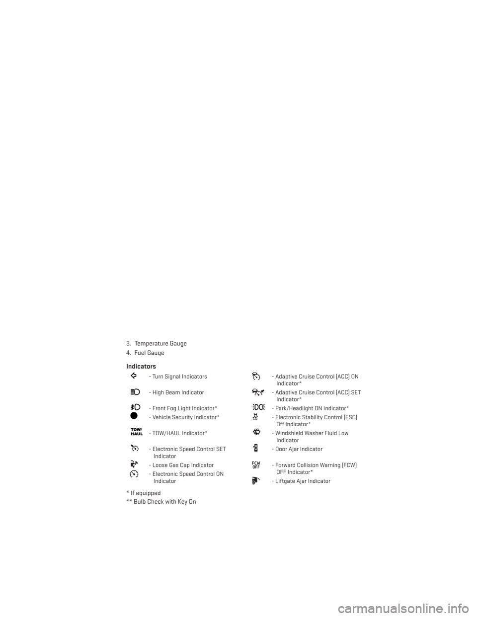
3. Temperature Gauge
4. Fuel Gauge
Indicators
- Turn Signal Indicators- Adaptive Cruise Control (ACC) ONIndicator*
- High Beam Indicator- Adaptive Cruise Control (ACC) SETIndicator*
- Front Fog Light Indicator*- Park/Headlight ON Indicator*
- Vehicle Security Indicator*- Electronic Stability Control (ESC)Off Indicator*
- TOW/HAUL Indicator*- Windshield Washer Fluid LowIndicator
- Electronic Speed Control SETIndicator- Door Ajar Indicator
- Loose Gas Cap Indicator- Forward Collision Warning (FCW)OFF Indicator*
- Electronic Speed Control ONIndicator- Liftgate Ajar Indicator
* If equipped
** Bulb Check with Key On
CONTROLS AT A GLANCE
9
Page 12 of 188
KEY FOB
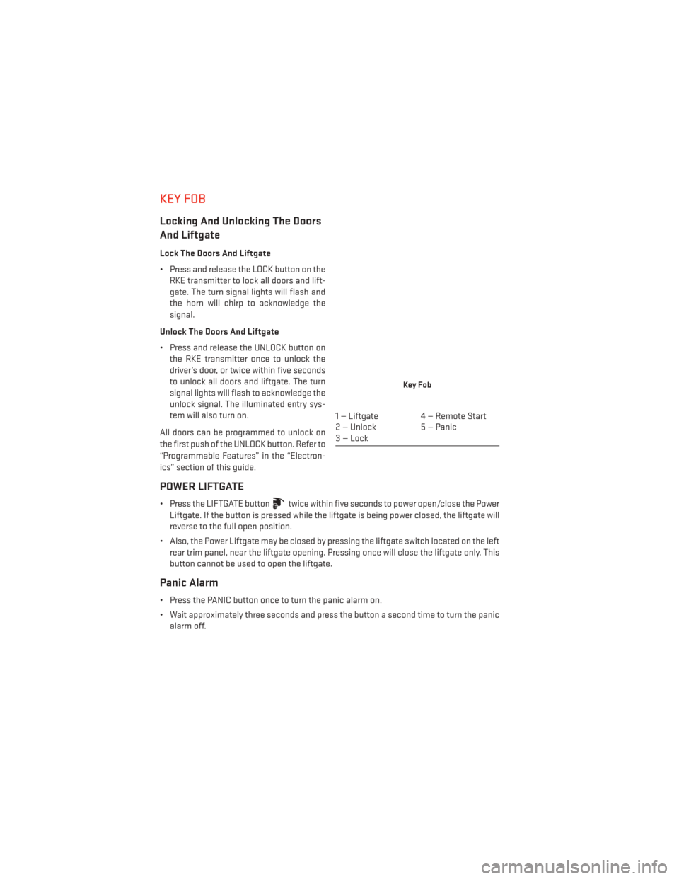
Locking And Unlocking The Doors
And Liftgate
Lock The Doors And Liftgate
• Press and release the LOCK button on theRKE transmitter to lock all doors and lift-
gate. The turn signal lights will flash and
the horn will chirp to acknowledge the
signal.
Unlock The Doors And Liftgate
• Press and release the UNLOCK button on the RKE transmitter once to unlock the
driver’s door, or twice within five seconds
to unlock all doors and liftgate. The turn
signal lights will flash to acknowledge the
unlock signal. The illuminated entry sys-
tem will also turn on.
All doors can be programmed to unlock on
the first push of the UNLOCK button. Refer to
“Programmable Features” in the “Electron-
ics” section of this guide.
POWER LIFTGATE
• Press the LIFTGATE buttontwice within five seconds to power open/close the Power
Liftgate. If the button is pressed while the liftgate is being power closed, the liftgate will
reverse to the full open position.
• Also, the Power Liftgate may be closed by pressing the liftgate switch located on the left rear trim panel, near the liftgate opening. Pressing once will close the liftgate only. This
button cannot be used to open the liftgate.
Panic Alarm
• Press the PANIC button once to turn the panic alarm on.
• Wait approximately three seconds and press the button a second time to turn the panicalarm off.
Key Fob
1 — Liftgate 4 — Remote Start
2 — Unlock 5 — Panic
3—Lock
GETTING STARTED
10
Page 16 of 188
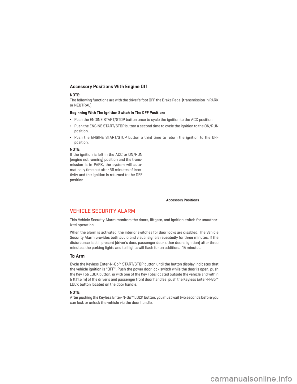
Accessory Positions With Engine Off
NOTE:
The following functions are with the driver’s foot OFF the Brake Pedal (transmission in PARK
or NEUTRAL).
Beginning With The Ignition Switch In The OFF Position:
• Push the ENGINE START/STOP button once to cycle the ignition to the ACC position.
• Push the ENGINE START/STOP button a second time to cycle the ignition to the ON/RUNposition.
• Push the ENGINE START/STOP button a third time to return the ignition to the OFF position.
NOTE:
If the ignition is left in the ACC or ON/RUN
(engine not running) position and the trans-
mission is in PARK, the system will auto-
matically time out after 30 minutes of inac-
tivity and the ignition is returned to the OFF
position.
VEHICLE SECURITY ALARM
This Vehicle Security Alarm monitors the doors, liftgate, and ignition switch for unauthor-
ized operation.
When the alarm is activated, the interior switches for door locks are disabled. The Vehicle
Security Alarm provides both audio and visual signals repeatedly for three minutes. If the
disturbance is still present (driver's door, passenger door, other doors, ignition) after three
minutes, the parking lights and tail lights will flash for an additional 15 minutes.
To Arm
Cycle the Keyless Enter-N-Go™ START/STOP button until the button display indicates that
the vehicle ignition is “OFF”. Push the power door lock switch while the door is open, push
the Key Fob LOCK button, or with one of the Key Fobs located outside the vehicle and within
5 ft (1.5 m) of the driver's and passenger front door handles, push the Keyless Enter-N-Go™
LOCK button located on the door handle.
NOTE:
After pushing the Keyless Enter-N-Go™ LOCK button, you must wait two seconds before you
can lock or unlock the vehicle via the door handle.
Accessory Positions
GETTING STARTED
14
Page 31 of 188
TILT/TELESCOPING STEERING COLUMN
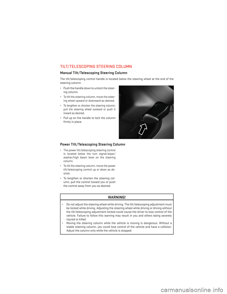
Manual Tilt/Telescoping Steering Column
The tilt/telescoping control handle is located below the steering wheel at the end of the
steering column.
• Push the handle down to unlock the steer-ing column.
•
To tilt the steering column, move the steer-
ing wheel upward or downward as desired.
•To lengthen or shorten the steering column,
pull the steering wheel outward or push it
inward as desired.
• Pull up on the handle to lock the column firmly in place.
Power Tilt/Telescoping Steering Column
•The power tilt/telescoping steering control
is located below the turn signal/wiper/
washer/high beam lever on the steering
column.
•To tilt the steering column, move the power
tilt/telescoping control up or down as de-
sired.
• To lengthen or shorten the steering col- umn, pull the control toward you or push
the control away from you as desired.
WARNING!
• Do not adjust the steering wheel while driving. The tilt/telescoping adjustment must be locked while driving. Adjusting the steering wheel while driving or driving without
the tilt/telescoping adjustment locked could cause the driver to lose control of the
vehicle. Failure to follow this warning may result in you and others being severely
injured or killed.
• Moving the steering column while the vehicle is moving is dangerous. Without a stable steering column, you could lose control of the vehicle and have a collision.
Adjust the column only while the vehicle is stopped.
GETTING STARTED
29
Page 33 of 188
Automatic High Beams
The Automatic High Beams system provides increased forward lighting at night by auto-
mating high beam control through the use of a digital camera mounted on the inside
rearview mirror. This camera detects vehicle specific light and automatically switches from
high beams to low beams until the approaching vehicle is out of view. This feature is
programmable through the Uconnect® system. Refer to “Uconnect® Settings ” in “Under-
standing Your Instrument Panel” in the Owner's Manual on the DVD for further details.
Instrument Panel Dimmer
• Rotate the dimmer control to the extreme bottom position to fully dim the instrumentpanel lights and prevent the interior lights from illuminating when a door is opened.
• Rotate the dimmer control up to increase the brightness of the instrument panel when the parking lights or headlights are on.
• Rotate the dimmer control up to the next detent position to fully brighten the odometer and radio when the parking lights or headlights are on.
• Rotate the dimmer control up to the last detent position to turn on the interior lighting.
• If your vehicle is equipped with a touchscreen, the dimming is programmable through the Uconnect® system. Refer to “Uconnect® Settings ” in “Understanding Your Instru-
ment Panel” in the Owner's Manual on the DVD for further details.
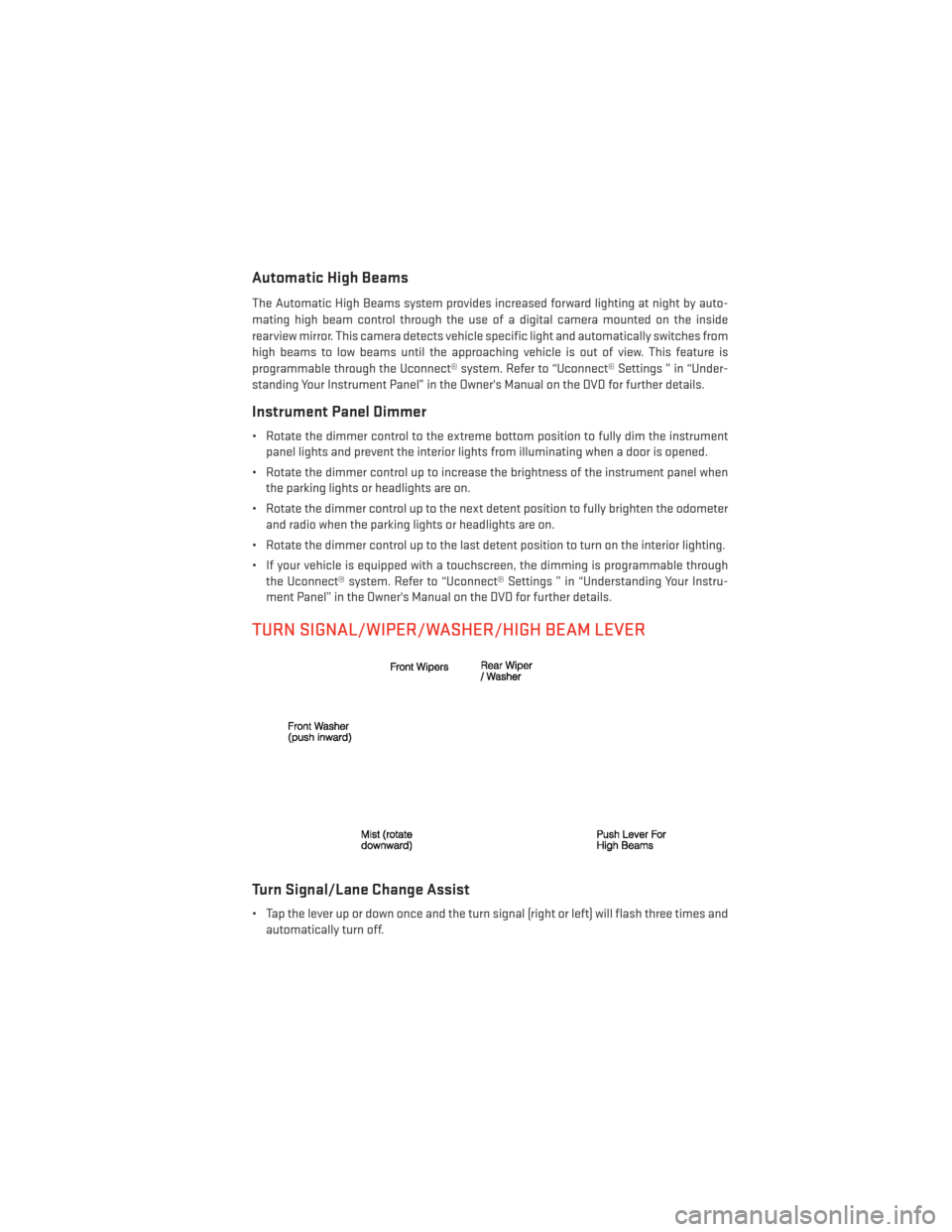
TURN SIGNAL/WIPER/WASHER/HIGH BEAM LEVER
Turn Signal/Lane Change Assist
• Tap the lever up or down once and the turn signal (right or left) will flash three times andautomatically turn off.
OPERATING YOUR VEHICLE
31
Page 61 of 188
4.Yelp® — Customers have the ability to search for nearby destinations or a point of
interest (POI) either by category or custom search by using keywords (for example,
“Italian restaurant”). Searching can be done by voice or using the touchscreen keypad.
Using the touchscreen, launch Yelp® by selecting the “Apps” icon, touch the “All Apps”
tab, and then touch “Yelp.” Using voice recognition press the Voice Command (VR)
button on the steering wheel and say “Launch Yelp®.”
5. Security Alarm Notification — The Security Alarm Notification feature notifies you via
email or text (SMS) message when the vehicle’s factory-installed security alarm system
has been set-off. There are a number of reasons why your alarm may have been
triggered, one of which could be that your vehicle was stolen. If so, please see the details
of the Stolen Vehicle Assistance service below. When you register, Security Alarm
Notification is automatically set to send you an email at the mail address you provide
should the alarm go off. You may also opt to have a text message sent to your mobile
device.
6. Stolen Vehicle Assistance — If your vehicle is stolen, contact local law enforcement
immediately to file a stolen vehicle report. Once this report has been filed, Uconnect®
care can help locate your vehicle. The Uconnect® Care agent will ask for the stolen
vehicle report number issued by local law enforcement. Then, using GPS technology and
the built-in wireless connection within your vehicle, the Uconnect® Care agent will be
able to locate the stolen vehicle and work with law enforcement to help recover it.
(Vehicle must be within the United States, have network coverage and must be regis-
tered with Uconnect® Access with an active subscription that includes the applicable
feature).
7. WiFi Hotspot — WiFi Hotspot is on-demand WiFi 3G connectivity that's built-in and ready
to go whenever you are. Once your vehicle is registered for Uconnect® Access, you can
purchase a Wifi Hotspot subscription at the Uconnect® Store. After you've made your
purchase, turn on your signal and connect your devices. It's never been easier to bring
your home or office with you.
Your vehicle must have a working electrical system for any of the in vehicle Uconnect®
features to operate.
Uconnect® Access Remote Features
If you own a compatible iPhone® or Android® powered device, the Uconnect® Access App
allows you to remotely lock or unlock your doors, start your engine or activate your horn
and lights from virtually anywhere (Vehicle must be within the United States and have
network coverage). You can download the App from Mopar Owner Connect or from the
App Store (iPhone) or Google Play store. Visit UconnectPhone.com to determine if your
device is compatible. For Uconnect® Phone customer support and to determine if your
device is compatible.
U.S. residents - visit UconnectPhone.com or call 1–877–855–8400
ELECTRONICS
59
Page 99 of 188
HD Radio
• HD Radio technology (available on Uconnect® 8.4AN) allows broadcasters to transmit ahigh-quality digital signal.
• With an HD radio receiver, the listener is provided with a clear sound that enhances the listening experience. HD radio can also transmit data such as song title or artist.
SiriusXM PREMIER OVER 160 CHANNELS
•Get every channel available on your satellite radio, and enjoy all you want, all in one place.
Hear commercial-free music plus sports, news, talk and entertainment. Get all the premium
programming, including Howard Stern, every NFL game, Oprah Radio®, every MLB® and
NHL® game, every NASCAR® race, Martha Stewart and more. And get 20+ extra channels,
including SiriusXM Latino, offering 20 channels of commercial free music, news, talk,
comedy, sports and more dedicated to Spanish language programming.
• To access SiriusXM Satellite Radio, touch the “SXM” soft-key on the main Radio screen.
•
The following describes features that are available when in SiriusXM Satellite Radio mode.
Seek Up/Seek Down
• Touch the “Seek” arrow soft-keys for less than two seconds to seek through channels in SXM mode.
• Touch and hold either “arrow” soft-key for more than two seconds to bypass channels without stopping. The radio will stop at the next listenable channel once the “arrow”
soft-key is released.
Direct Tune
• Tune directly to a SXM channel by pressing the “Tune” soft-key on the screen, and entering the desired station number.
Jump
• Automatically tells you when Traffic & Weather for a favorite city is available, and gives you the option to switch to that channel. Touch “Jump” to activate the feature. After
listening to Traffic and Weather, touch “Jump” again to return to the previous channel.
Fav
• Activates the favorites menu. You can add up to 50 favorite artists or songs. Just touch “Add Fav Artist” or “Add Fav Song” while the song is playing. You will then be alerted any
time one of these songs, or works by these artists, is playing on other SiriusXM channels.
SiriusXM Parental Controls
• You can skip or hide certain channels from view if you do not want access to them. Touch the “More” soft-key, then the “Settings” soft-key, next touch the “Sirius Setup” soft-key,
then select “Channel Skip”. Touch the box, check-mark, next to the channel you want
skipped. They will not show up in normal usage.
•
SiriusXM also offers the option to permanently block selected channels. Call (1-888-601-6297
for U.S. customers, 1-877-438-9677 for Canadian customers) and request the Family - Friendly
Package.
ELECTRONICS
97
Page 121 of 188
4. Continue to hold both buttons and observe the indicator light. The HomeLink® indicatorwill flash slowly and then rapidly after HomeLink® has received the frequency signal
from the hand-held transmitter. Release both buttons after the indicator light changes
from slow to rapid.
5. At the garage door opener motor (in the garage), locate the “LEARN” or “TRAINING” button. This can usually be found where the hanging antenna wire is attached to the
garage door opener motor. Firmly press and release the “LEARN” or “TRAINING” button.
NOTE:
You have 30 seconds in which to initiate the next step after the LEARN button has been
pressed.
6.
Return to the vehicle and press the programmed HomeLink® button twice (holding the
button for two seconds each time). If the device is plugged in and activates, programming
is complete.
NOTE:
If the device does not activate, press the button a third time (for two seconds) to complete
the training.
7. To program the remaining two HomeLink® buttons, repeat each step for each remaining button. DO NOT erase the channels.
Programming A Non-Rolling Code
NOTE:
For programming Garage Door Openers manufactured before 1995.
1. Turn the ignition switch to the ON/RUN position.
2. Place the hand-held transmitter 1 to 3 inches (3 to 8 cm) away from the HomeLink® button you wish to program while keeping the HomeLink® indicator light in view.
3. Simultaneously press and hold both the HomeLink® button you want to program and the hand-held transmitter button.
4. Continue to hold both buttons and observe the indicator light. The HomeLink® indicator will flash slowly and then rapidly after HomeLink® has received the frequency signal
from the hand-held transmitter. Release both buttons after the indicator light changes
from slow to rapid.
5. Press and hold the programmed HomeLink® button and observe the indicator light. If the indicator light stays on constantly, programming is complete and the garage door (or
device) should activate when the HomeLink® button is pressed.
6. To program the two remaining HomeLink® buttons, repeat each step for each remaining button. DO NOT erase the channels.
ELECTRONICS
119
Page 134 of 188
When the malfunction indicator is illuminated, the system may not be able to detect or
signal low tire pressure as intended. TPMS malfunctions may occur for a variety of reasons,
including the installation of replacement or alternate tires or wheels on the vehicle that
prevent the TPMS from functioning properly. Always check the TPMS malfunction telltale
after replacing one or more tires or wheels on your vehicle, to ensure that the replacement
or alternate tires and wheels allow the TPMS to continue to function properly.
NOTE:
Tire pressures change by approximately 1 psi (7 kPa) per 12° F (7° C) of air temperature
change. Keep this in mind when checking tire pressure inside a garage, especially in the
Winter. Example: If garage temperature is 68°F (20°C) and the outside temperature is 32°F
(0°C), then the cold tire inflation pressure should be increased by 3 psi (21 kPa), which equals
1 psi (7 kPa) for every 12°F (7°C) for this outside temperature condition.
CAUTION!
The TPMS has been optimized for the original equipment tires and wheels. TPMS
pressures and warning have been established for the tire size equipped on your vehicle.
Undesirable system operation or sensor damage may result when using replacement
equipment that is not of the same size, type, and/or style. Aftermarket wheels can cause
sensor damage. Do not use tire sealant from a can, or balance beads if your vehicle is
equipped with a TPMS, as damage to the sensors may result.
BRAKE- Brake Warning Light
This light monitors various brake functions, including brake fluid level and parking brake
application. If the brake light turns on it may indicate that the parking brake is applied, that the
brake fluid level is low, or that there is a problem with the anti-lock brake system reservoir.
If the light remains on when the parking brake has been disengaged, and the fluid level is at
the full mark on the master cylinder reservoir, it indicates a possible brake hydraulic system
malfunction or that a problem with the Brake Booster has been detected by the Anti-Lock
Brake System (ABS)/Electronic Stability Control (ESC) system. In this case, the light will
remain on until the condition has been corrected. If the problem is related to the brake
booster, the ABS pump will run when applying the brake and a brake pedal pulsation may be
felt during each stop.
The dual brake system provides a reserve braking capacity in the event of a failure to a
portion of the hydraulic system. A leak in either half of the dual brake system is indicated by
the Brake Warning Light, which will turn on when the brake fluid level in the master cylinder
has dropped below a specified level. The light will remain on until the cause is corrected.
Vehicles equipped with the Anti-Lock Brake System (ABS), are also equipped with Electronic
Brake Force Distribution (EBD). In the event of an EBD failure, the Brake Warning Light will
turn on along with the ABS Light. Immediate repair to the ABS system is required.
WHAT TO DO IN EMERGENCIES
132