battery DODGE DURANGO 2015 3.G Owner's Manual
[x] Cancel search | Manufacturer: DODGE, Model Year: 2015, Model line: DURANGO, Model: DODGE DURANGO 2015 3.GPages: 236, PDF Size: 35.01 MB
Page 188 of 236
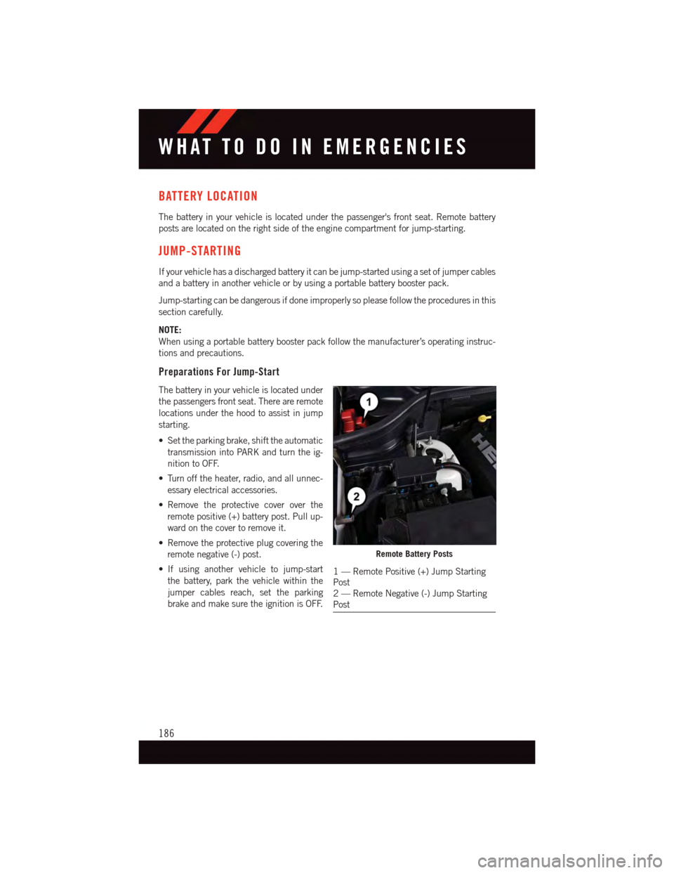
BATTERY LOCATION
The battery in your vehicle is located under the passenger's front seat. Remote battery
posts are located on the right side of the engine compartment for jump-starting.
JUMP-STARTING
If your vehicle has a discharged battery it can be jump-started using a set of jumper cables
and a battery in another vehicle or by using a portable battery booster pack.
Jump-starting can be dangerous if done improperly so please follow the procedures in this
section carefully.
NOTE:
When using a portable battery booster pack follow the manufacturer’s operating instruc-
tions and precautions.
Preparations For Jump-Start
The battery in your vehicle is located under
the passengers front seat. There are remote
locations under the hood to assist in jump
starting.
•Settheparkingbrake,shifttheautomatic
transmission into PARK and turn the ig-
nition to OFF.
•Turnofftheheater,radio,andallunnec-
essary electrical accessories.
•Remove the protective cover over the
remote positive (+) battery post. Pull up-
ward on the cover to remove it.
•Removetheprotectiveplugcoveringthe
remote negative (-) post.
•If using another vehicle to jump-start
the battery, park the vehicle within the
jumper cables reach, set the parking
brake and make sure the ignition is OFF.
Remote Battery Posts
1—RemotePositive(+)JumpStartingPost2—RemoteNegative(-)JumpStartingPost
WHAT TO DO IN EMERGENCIES
186
Page 189 of 236
Jump-Starting Procedure
1. Connect the positive(+)end of the jumper cable to the remote positive(+)post of the
vehicle with discharged battery.
2. Connect the opposite end of the positive(+)jumper cable to the positive(+)post of the
booster battery.
3. Connect the negative(-)end of the jumper cable to the negative(-)post of the booster
battery.
4. Connect the opposite end of the negative(-)jumper cable to the remote negative(-)
post of the vehicle with the discharged battery.
5. Start the engine in the vehicle that has the booster battery, let the engine idle a few
minutes, and then start the engine in the vehicle with the discharged battery.
Once the engine is started, remove the jumper cables in the reverse sequence:
1. Disconnect the negative(-)end of the jumper cable from the remote negative(-)post
of the vehicle with the discharged battery.
2. Disconnect the opposite end of the negative(-)jumper cable from the negative(-)post
of the booster battery.
3. Disconnect the positive(+)end of the jumper cable from the positive(+)post of the
booster battery.
4. Disconnect the opposite end of the positive(+)jumper cable from the remote positive
(+)post of the discharged vehicle.
5. Reinstall the protective cover over the remote positive(+)post of the vehicle with the
discharged battery.
6. Reinstall the protective plug over the remote negative(-)post of the vehicle with the
discharged battery.
NOTE:
If frequent jump-starting is required to start your vehicle you should have the battery and
charging system inspected at your authorized dealer.
CAUTION!
•Donotuseaportablebatteryboosterpackoranyotherboostersourcewithasystem
voltage greater than 12 Volts or damage to the battery, starter motor, alternator or
electrical system may occur.
•Failuretofollowtheseprocedurescouldresultindamagetothechargingsystemof
the booster vehicle or the discharged vehicle.
•Accessoriesthatcanbepluggedintothevehiclepoweroutletsdrawpowerfromthe
vehicle’s battery, even when not in use (e.g., cellular phones, etc.). Eventually, if
plugged in long enough, the vehicle’s battery discharges sufficiently to degrade
battery life and/or prevent the engine from starting.
WHAT TO DO IN EMERGENCIES
187
Page 190 of 236
WARNING!
•Whentemperaturesarebelowthefreezingpoint,electrolyteinadischargedbattery
may freeze. Do not attempt jump-starting because the battery could rupture or
explode and cause personal injury. Battery temperature must be brought above the
freezing point before attempting a jump-start.
•Takecaretoavoidtheradiatorcoolingfanwheneverthehoodisraised.Itcanstart
anytime the ignition switch is on. You can be injured by moving fan blades.
•Removeanymetaljewelry,suchaswatchbandsorbracelets,thatmightmakean
inadvertent electrical contact. You could be severely injured.
•Batteriescontainsulfuricacidthatcanburnyourskinoreyesandgenerate
hydrogen gas which is flammable and explosive. Keep open flames or sparks away
from the battery.
•Donotallowvehiclestotoucheachotherasthiscouldestablishaground
connection and personal injury could result.
•Failuretofollowthisprocedurecouldresultinpersonalinjuryorpropertydamage
due to battery explosion.
•Donotconnectthecabletothenegativepost(-)ofthedischargedbattery.The
resulting electrical spark could cause the battery to explode and could result in
personal injury.
WHAT TO DO IN EMERGENCIES
188
Page 204 of 236
Required Maintenance
Refer to the Maintenance Schedules on the following pages for required maintenance.
At Every Oil Change Interval As Indicated By Oil Change Indicator System:
•Change oil and filter.
•Rotatethetires.Rotate at the first sign of irregular wear, even if it occurs before the oil
indicator system turns on.
•Inspect battery and clean and tighten terminals as required.
•Inspect brake pads, shoes, rotors, drums, hoses and park brake.
•Inspect engine cooling system protection and hoses.
•Inspect exhaust system.
•Inspect engine air cleaner if using in dusty or off-road conditions.
MAINTAINING YOUR VEHICLE
202
Page 208 of 236
FUSES
WARNING!
•Whenreplacingablownfuse,alwaysuseanappropriatereplacementfusewiththe
same amp rating as the original fuse. Never replace a fuse with another fuse of
higher amp rating. Never replace a blown fuse with metal wires or any other
material. Failure to use proper fuses may result in serious personal injury, fire and/or
property damage.
•Beforereplacingafuse,makesurethattheignitionisoffandthatalltheother
services are switched off and/or disengaged.
•Ifthereplacedfuseblowsagain,contactanauthorizeddealer.
•Ifageneralprotectionfuseforsafetysystems(airbagsystem,brakingsystem),
power unit systems (engine system, gearbox system) or steering system blows,
contact an authorized dealer.
Power Distribution Center
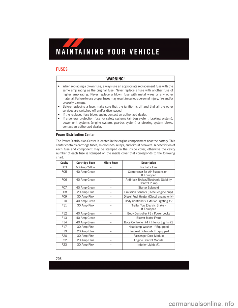
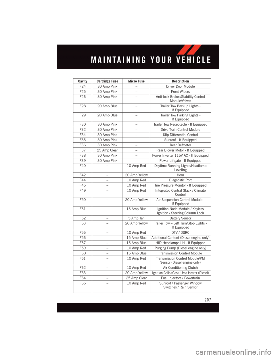
The Power Distribution Center is located in the engine compartment near the battery. This
center contains cartridge fuses, micro fuses, relays, and circuit breakers. A description of
each fuse and component may be stamped on the inside cover, otherwise the cavity
number of each fuse is stamped on the inside cover that corresponds to the following
chart.
Cavity Cartridge Fuse Micro FuseDescription
F03 60 Amp Yellow –Radiator Fan
F05 40 Amp Green –Compressor for Air Suspension -If Equipped
F06 40 Amp Green – Anti-lock Brakes/Electronic StabilityControl Pump
F07 40 Amp Green –Starter Solenoid
F08 20 Amp Blue–EmissionSensors(Dieselengineonly)
F09 30 Amp Pink–DieselFuelHeater(Dieselengineonly)
F10 40 Amp Green – Body Controller / Exterior Lighting #2
F11 30 Amp Pink–Tr a i l e r To w E l e c t r i c B r a k e -If Equipped
F12 40 Amp Green –Body Controller #3 / Power Locks
F13 40 Amp Green –Blower Motor Front
F14 40 Amp Green – Body Controller #4 / Interior Lights #2
F17 30 Amp Pink–Headlamp Washer- If Equipped
F19 20 Amp Blue–Headrest Solenoid- If Equipped
F20 30 Amp Pink–Passenger Door Module
F22 20 Amp Blue–Engine Control Module
F23 30 Amp Pink–Interior Lights #1
MAINTAINING YOUR VEHICLE
206
Page 209 of 236
Cavity Cartridge Fuse Micro FuseDescription
F24 30 Amp Pink–Driver Door Module
F25 30 Amp Pink–Front Wipers
F26 30 Amp Pink–Anti-lock Brakes/Stability ControlModule/Valves
F28 20 Amp Blue–Tr a i l e r To w B a c k u p L i g h t s -If Equipped
F29 20 Amp Blue–Tr a i l e r To w P a r k i n g L i g h t s -If Equipped
F30 30 Amp Pink–TrailerTowReceptacle-IfEquipped
F32 30 Amp Pink–Drive Train Control Module
F34 30 Amp Pink–Slip Differential Control
F35 30 Amp Pink–Sunroof - If Equipped
F36 30 Amp Pink–Rear Defroster
F37 25 Amp Clear –Rear Blower Motor - If Equipped
F38 30 Amp Pink–PowerInverter115VAC-IfEquipped
F39 30 Amp Pink–Power Liftgate - If Equipped
F40–10 Amp Red Daytime Running Lights/HeadlampLeveling
F42–20AmpYellowHorn
F44–10 Amp RedDiagnostic Port
F46–10 Amp Red Tire Pressure Monitor - If Equipped
F49–10 Amp Red Integrated Central Stack / ClimateControl
F50–20AmpYellowAirSuspensionControlModule-If Equipped
F51–15 Amp Blue Ignition Node Module / KeylessIgnition / Steering Column Lock
F52–5AmpTanBattery Sensor
F53–20AmpYellowTrailerTow–LeftTurn/StopLights-If Equipped
F55–10 Amp RedDTV / DSRC
F56–15 Amp Blue Additional Content (Diesel engine only)
F57–15 Amp Blue HID Headlamps LH - If Equipped
F59–10 Amp Red Purging Pump (Diesel engine only)
F60–15 Amp Blue Transmission Control Module
F61–10 Amp Red Transmission Control Module/PMSensor (Diesel engine only)
F62–10 Amp Red Air Conditioning Clutch
F63–20AmpYellowIgnition Coils (Gas), Urea Heater (Diesel)
F64–25AmpClearFuelInjectors/Powertrain
F66–10 Amp Red Sunroof / Passenger WindowSwitches / Rain Sensor
MAINTAINING YOUR VEHICLE
207
Page 222 of 236
Access
Uconnect®..............67
Access, Uconnect®...........67
Adaptive Cruise Control (ACC)
(Cruise Control) . . . . . . . . . . . .44
Adding Engine Coolant (Antifreeze)..201
Adding Fuel..............210
Adding Washer Fluid..........201
Air Bag
Advanced Front Air Bag.......16
Advance Front Air Bag.......16Air Bags . . . . . . . . . . . . . . .16Air Bag Warning Light . . . . .16, 172Driver Knee Air Bag.........18Front Air Bag . . . . . . . . . . . .16Passenger Knee Air Bag.......18Rollover . . . . . . . . . . . . . . .16Side Air Bags............18Side Impact Curtains........18Side Impacts.............16Air Bag, Side . . . . . . . . . . . . . . .16Air Cleaner, Engine(Engine Air Cleaner Filter).....201Air Conditioner Maintenance.....201Air Conditioning...........55,58Air Conditioning Refrigerant......201Air Conditioning System........201AlarmArm The System...........15Disarm The System.........15Vehicle Security Alarm.......15Alarm (Security Alarm)......15,173All Wheel Drive (AWD).........157Antifreeze (Engine Coolant) . . .198, 201Disposal . . . . . . . . . . . . . .201Anti-Lock Brake System (ABS)....172APPUconnect®Access..........70Appearance Care............201Arming System (Security Alarm)....15Assistance Towing...........168Automatic Dimming Mirror.......51Automatic Headlights..........41Automatic High Beams.........41Automatic Temperature Control (ATC)...55SYNC Temperature Button.....59Automatic TransmissionFluid Type . . . . . . . . . . . . .200
Axle Fluid . . . . . . . . . . . . . . . .200
Back-Up Camera............61Battery . . . . . . . . . . . . . .186, 201Charging System Light......171Blind Spot Monitoring..........61Body Mechanism Lubrication.....201Brake Fluid . . . . . . . . . . . . . . .200Brakes.................201Brake System.............201Master Cylinder..........201Warning Light . . . . . . . . . . .169Break-In Recommendations,New Vehicle . . . . . . . . . . . . .39Bulb Replacement...........214
Calibration, Compass.........148Capacities, Fluid............198Caps, FillerFuel................192Oil (Engine)............201Cargo CompartmentLuggage Carrier..........160Car Washes . . . . . . . . . . . . . . .201Change Oil Indicator..........174Changing A Flat Tire..........176Charging System Light.........171Check Engine Light(Malfunction Indicator Light). . . .170Child Restraint...........19,20Arm Rest Tether . . . . . . . . . . .22Child RestraintsCenter Seat LATCH.........21Child Restraints...........20Child Tether Anchorage Locations...22Locating The LATCH Anchorages...20Lower Anchors And TethersFor Children . . . . . . . . . .19, 20CleaningWheels...............201Windshield Wiper Blades.....201Climate Control . . . . . . . . . . . . .55Clock . . . . . . . . . . . . . . . . . . .84Clock Setting...............84Cluster Warning/Indicator LightsAir Bag Warning Light . . . . . . .172Brake Warning Light . . . . . . . .169
INDEX
220
Page 223 of 236
Electronic Speed Control ON
Indicator . . . . . . . . . . . . . .173
Electronic Speed Control SET
Indicator . . . . . . . . . . . . . .173
Electronic Stability Control (ESC)
OFF Indicator Light . . . . . . . .173
Front Fog Light Indicator . . . . .173
High Beam Indicator.......173
Park/Headlight ON Indicator . . .173
Tu r n S i g n a l I n d i c a t o r.......173Vehicle Security Light.......173Clutch . . . . . . . . . . . . . . . . .201Clutch Fluid . . . . . . . . . . . . . .201Compact Spare Tire..........212Compass Calibration..........148Cooling System.............201Adding Coolant (Antifreeze)....201Coolant Capacity.........198Coolant Level...........201Disposal of Used Coolant.....201Drain, Flush, and Refill......201Inspection . . . . . . . . . . . . .201Points to Remember.......201Pressure Cap . . . . . . . . . . .201Selection of Coolant(Antifreeze)......198, 199, 201Corrosion Protection..........201Cruise Control (Speed Control).....42Cruise Light . . . . . . . . . . . . . . .42Customer Assistance.......215, 216Customer Programmable Features . .150
Defects, Reporting...........216Dimmer Control.............42Dimmer Switch, Headlight.......42Disabled Vehicle Towing . . . . . . . .168Disarming, Security System.......15Discharged Battery...........186DisposalAntifreeze (Engine Coolant)....201Driver Cockpit...............7Driver Information DisplayProgrammable Features......149Driver Information Display (DID)Display . . . . . . . . . . . . . . .148
Driver Information Display (DID)..150Selectable Menu Items......150
E-85 Fuel................200
ECO . . . . . . . . . . . . . . . . . . .148
Economy (Fuel) Mode..........54
Electronically Shifted Transfer Case . .157
Electronics
Yo u r Ve h i c l e ' s S o u n d S y s t e m....64
Electronic Speed Control (Cruise
Control) . . . . . . . . . . . . . . . .42
Electronic Stability Control (ESC) . . .171
Electronic Stability Control (ESC)OFF Indicator . . . . . . . . . . . .173Electronic Throttle Control WarningLight . . . . . . . . . . . . . . . . .172Emergency, In Case ofJacking..............176Overheating............175To w i n g . . . . . . . . . . . . . . . 1 6 8EngineAir Cleaner . . . . . . . . . . . . .201Break-In Recommendations....39Checking Oil Level.........201Compartment............194Cooling . . . . . . . . . . . . . . .201Fuel Requirements.........198Malfunction Indicator(Check Engine)..........170Oil . . . . . . . . . . . . . .198, 201Oil Filler Cap...........201Oil Selection . . . . .198, 199, 201Overheating............175Starting...............14Stopping..............14Ethanol.................200Event Data Recorder..........192Exhaust System............201Exterior Lights . . . . . . . . . . . . .214
FA Q . . . . . . . . . . . . . . . . . . . 2 1 8FiltersAir Cleaner . . . . . . . . . . . . .201Engine Oil.............201Engine Oil Disposal........201FlashersTu r n S i g n a l............173Flexible Fuel Vehicles.........200Fluid Capacities............198Fluids . . . . . . . . . . . . . . . . . .200
Fluids, Lubricants and Genuine Parts..199
INDEX
221
Page 224 of 236
Fog Lights . . . . . . . . . . . . .41, 173
Folding Front Passenger Seat......31
Folding Rear Seat..........31,33
Forward Collision Warning........49
Four Wheel Drive............157
Operation.............157
Systems . . . . . . . . . . . . . .157
Four Wheel Drive Operation......157
Freeing A Stuck Vehicle . . . . . . . .191
Frequently Asked Questions......218
FuelEconomy Mode...........54Ethanol..............200Filler Door Emergency Release . .211Requirements...........198Specifications...........199Ta n k C a p a c i t y...........198Fuel, Flexible..............200Fuses . . . . . . . . . . . . . . . . . .206
General Maintenance.........201Glass Cleaning . . . . . . . . . . . . .201
Hands-Free Phone (Uconnect®). . . .137HeadlightsAutomatic . . . . . . . . . . . . . .41Cleaning..............201Dimmer Switch...........42High Beam . . . . . . . . . . . . .41High Beam/Low Beam SelectSwitch . . . . . . . . . . . . . . . .41Heated Mirrors..............58Heated Seats..............34Heated Steering Wheel.........36High Beam Indicator..........173High Beam/Low Beam Select(Dimmer) Switch...........41HomeLink®(Garage Door Opener) . .152Hood Release . . . . . . . . . . . . .193
Identifying Your Radio..........66Instrument Cluster............8Indicators . . . . . . . . . . . . . . .8Instrument Cluster Indicator Lights . .173Instrument Panel Cover........201Instrument Panel Lens Cleaning . . .201Interior and Instrument Lights......7Interior Appearance Care.......201
Intermittent Wipers (Delay Wipers) . . .40
Introduction................2
In Vehicle Features
Uconnect®Access..........74
Inverter Outlet (115V).........154
Inverter, Power.............154
iPod®/USB/MP3 Control
Bluetooth®Streaming
Audio.......87,103, 131, 137
Jacking Instructions..........179Jack Location..............176Jack Operation..........176, 179Jump Starting.............186
Key Fob . . . . . . . . . . . . . . . . .10Arm The Alarm . . . . . . . . . . .15Disarm The Alarm . . . . . . . . . .15Lock The Doors...........10Unlock The Doors..........10Keyless Enter-N-Go...........10Lock/Unlock..........12,13Starting/Stopping..........14Keyless Enter-N-Go™..........12Passive Entry............12
Lane Change Assist...........40Lap/Shoulder Belts...........15LATCH (Lower Anchors and Tether forCHildren) . . . . . . . . . . . . . . .21Liftgate . . . . . . . . . . . . . . . . . .10Liftgate, Power..............10LightsFog . . . . . . . . . . . . . . . . .173Headlights..............41High Beam Indicator.......173Hill Descent Control Indicator . .173Low Fuel..............173Security Alarm...........173LocksLiftgate, Tailgate . . . . . . . . . .10Lubrication, Body...........201Luggage Rack (Roof Rack)......160
Maintenance Free Battery.......201Maintenance, General.........201Maintenance Procedures.......201Maintenance Record..........205
INDEX
222