charging DODGE DURANGO 2015 3.G User Guide
[x] Cancel search | Manufacturer: DODGE, Model Year: 2015, Model line: DURANGO, Model: DODGE DURANGO 2015 3.GPages: 236, PDF Size: 35.01 MB
Page 156 of 236

Using HomeLink®
To o p e r a t e , p u s h a n d r e l e a s e t h e p r o g r a m m e d H o m e L i n k®button. Activation will now
occur for the programmed device (e.g., garage door opener, gate operator, security system,
entry door lock, home/office lighting, etc.). The hand-held transmitter of the device may
also be used at any time.
WARNING!
•Yourmotorizeddoororgatewillopenandclosewhileyouareprogrammingthe
universal transceiver. Do not program the transceiver if people or pets are in the
path of the door or gate.
•Donotrunyourvehicleinaclosedgarageorconfinedareawhileprogrammingthe
transceiver. Exhaust gas from your vehicle contains Carbon Monoxide (CO) which is
odorless and colorless. Carbon Monoxide is poisonous when inhaled and can cause
you and others to be severely injured or killed.
POWER INVERTER
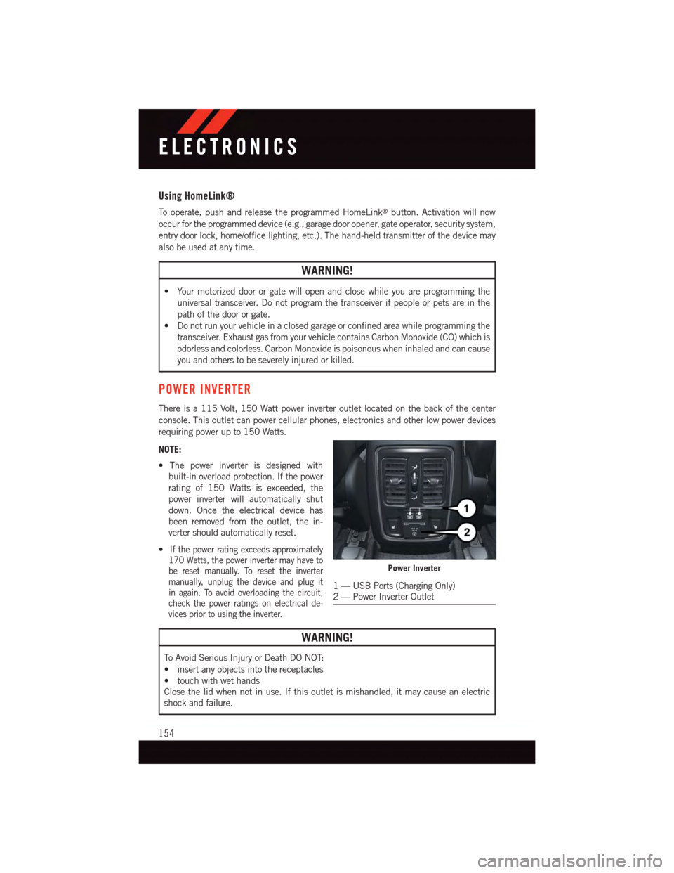
There is a 115 Volt, 150 Watt power inverter outlet located on the back of the center
console. This outlet can power cellular phones, electronics and other low power devices
requiring power up to 150 Watts.
NOTE:
•Thepowerinverterisdesignedwith
built-in overload protection. If the power
rating of 150 Watts is exceeded, the
power inverter will automatically shut
down. Once the electrical device has
been removed from the outlet, the in-
verter should automatically reset.
•If the power rating exceeds approximately170 Watts, the power inverter may have tobe reset manually. To reset the invertermanually, unplug the device and plug itin again. To avoid overloading the circuit,check the power ratings on electrical de-vices prior to using the inverter.
WARNING!
To A v o i d S e r i o u s I n j u r y o r D e a t h D O N O T:
•insertanyobjectsintothereceptacles
•touchwithwethands
Close the lid when not in use. If this outlet is mishandled, it may cause an electric
shock and failure.
Power Inverter
1—USBPorts(ChargingOnly)2—PowerInverterOutlet
ELECTRONICS
154
Page 173 of 236

WARNING!
Amalfunctioningcatalyticconverter,asreferencedabove,canreachhighertempera-
tures than in normal operating conditions. This can cause a fire if you drive slowly or
park over flammable substances such as dry plants, wood, cardboard, etc. This could
result in death or serious injury to the driver, occupants or others.
-ElectronicStabilityControl(ESC)Activation/MalfunctionIndicatorLight
The “ESC Activation/Malfunction Indicator Light” in the instrument cluster will come on
when the ignition switch is turned to the ON/RUN position. It should go out with the
engine running. If the “ESC Activation/Malfunction Indicator Light” comes on continu-
ously with the engine running, a malfunction has been detected in the ESC system. If this
light remains on after several ignition cycles, and the vehicle has been driven several miles
(kilometers) at speeds greater than 30 mph (48 km/h), see your authorized dealer as soon
as possible to have the problem diagnosed and corrected.
NOTE:
•The“ESCOffIndicatorLight”andthe“ESCActivation/MalfunctionIndicatorLight”
come on momentarily each time the ignition switch is turned to ON/RUN.
•EachtimetheignitionisturnedtoON/RUN,theESCsystemwillbeON,evenifitwas
turned off previously.
•TheESCsystemwillmakebuzzingorclickingsoundswhenitisactive.Thisisnormal;
the sounds will stop when ESC becomes inactive following the maneuver that caused
the ESC activation.
•Toimprovethevehicle'stractionwhenstartingoffindeepsnow,sandorgravel,itmay
be desirable to switch the ESC system to Partial Off mode by momentarily pressing the
ESC Offswitch located below the climate controls, on the switch panel.
-ChargingSystemLight
This light shows the status of the electrical charging system. If the charging system light
remains on, it means that the vehicle is experiencing a problem with the charging system.
We recommend you do not continue driving if the charging system light is on. Have the
vehicle serviced immediately.
-OilPressureWarningLight
This light indicates low engine oil pressure. If the light turns on while driving, stop the
vehicle and shut off the engine as soon as possible. A chime will sound for four minutes
when this light turns on.
We recommend you do not operate the vehicle or engine damage will occur. Have the
vehicle serviced immediately.
WHAT TO DO IN EMERGENCIES
171
Page 189 of 236

Jump-Starting Procedure
1. Connect the positive(+)end of the jumper cable to the remote positive(+)post of the
vehicle with discharged battery.
2. Connect the opposite end of the positive(+)jumper cable to the positive(+)post of the
booster battery.
3. Connect the negative(-)end of the jumper cable to the negative(-)post of the booster
battery.
4. Connect the opposite end of the negative(-)jumper cable to the remote negative(-)
post of the vehicle with the discharged battery.
5. Start the engine in the vehicle that has the booster battery, let the engine idle a few
minutes, and then start the engine in the vehicle with the discharged battery.
Once the engine is started, remove the jumper cables in the reverse sequence:
1. Disconnect the negative(-)end of the jumper cable from the remote negative(-)post
of the vehicle with the discharged battery.
2. Disconnect the opposite end of the negative(-)jumper cable from the negative(-)post
of the booster battery.
3. Disconnect the positive(+)end of the jumper cable from the positive(+)post of the
booster battery.
4. Disconnect the opposite end of the positive(+)jumper cable from the remote positive
(+)post of the discharged vehicle.
5. Reinstall the protective cover over the remote positive(+)post of the vehicle with the
discharged battery.
6. Reinstall the protective plug over the remote negative(-)post of the vehicle with the
discharged battery.
NOTE:
If frequent jump-starting is required to start your vehicle you should have the battery and
charging system inspected at your authorized dealer.
CAUTION!
•Donotuseaportablebatteryboosterpackoranyotherboostersourcewithasystem
voltage greater than 12 Volts or damage to the battery, starter motor, alternator or
electrical system may occur.
•Failuretofollowtheseprocedurescouldresultindamagetothechargingsystemof
the booster vehicle or the discharged vehicle.
•Accessoriesthatcanbepluggedintothevehiclepoweroutletsdrawpowerfromthe
vehicle’s battery, even when not in use (e.g., cellular phones, etc.). Eventually, if
plugged in long enough, the vehicle’s battery discharges sufficiently to degrade
battery life and/or prevent the engine from starting.
WHAT TO DO IN EMERGENCIES
187
Page 222 of 236

Access
Uconnect®..............67
Access, Uconnect®...........67
Adaptive Cruise Control (ACC)
(Cruise Control) . . . . . . . . . . . .44
Adding Engine Coolant (Antifreeze)..201
Adding Fuel..............210
Adding Washer Fluid..........201
Air Bag
Advanced Front Air Bag.......16
Advance Front Air Bag.......16Air Bags . . . . . . . . . . . . . . .16Air Bag Warning Light . . . . .16, 172Driver Knee Air Bag.........18Front Air Bag . . . . . . . . . . . .16Passenger Knee Air Bag.......18Rollover . . . . . . . . . . . . . . .16Side Air Bags............18Side Impact Curtains........18Side Impacts.............16Air Bag, Side . . . . . . . . . . . . . . .16Air Cleaner, Engine(Engine Air Cleaner Filter).....201Air Conditioner Maintenance.....201Air Conditioning...........55,58Air Conditioning Refrigerant......201Air Conditioning System........201AlarmArm The System...........15Disarm The System.........15Vehicle Security Alarm.......15Alarm (Security Alarm)......15,173All Wheel Drive (AWD).........157Antifreeze (Engine Coolant) . . .198, 201Disposal . . . . . . . . . . . . . .201Anti-Lock Brake System (ABS)....172APPUconnect®Access..........70Appearance Care............201Arming System (Security Alarm)....15Assistance Towing...........168Automatic Dimming Mirror.......51Automatic Headlights..........41Automatic High Beams.........41Automatic Temperature Control (ATC)...55SYNC Temperature Button.....59Automatic TransmissionFluid Type . . . . . . . . . . . . .200
Axle Fluid . . . . . . . . . . . . . . . .200
Back-Up Camera............61Battery . . . . . . . . . . . . . .186, 201Charging System Light......171Blind Spot Monitoring..........61Body Mechanism Lubrication.....201Brake Fluid . . . . . . . . . . . . . . .200Brakes.................201Brake System.............201Master Cylinder..........201Warning Light . . . . . . . . . . .169Break-In Recommendations,New Vehicle . . . . . . . . . . . . .39Bulb Replacement...........214
Calibration, Compass.........148Capacities, Fluid............198Caps, FillerFuel................192Oil (Engine)............201Cargo CompartmentLuggage Carrier..........160Car Washes . . . . . . . . . . . . . . .201Change Oil Indicator..........174Changing A Flat Tire..........176Charging System Light.........171Check Engine Light(Malfunction Indicator Light). . . .170Child Restraint...........19,20Arm Rest Tether . . . . . . . . . . .22Child RestraintsCenter Seat LATCH.........21Child Restraints...........20Child Tether Anchorage Locations...22Locating The LATCH Anchorages...20Lower Anchors And TethersFor Children . . . . . . . . . .19, 20CleaningWheels...............201Windshield Wiper Blades.....201Climate Control . . . . . . . . . . . . .55Clock . . . . . . . . . . . . . . . . . . .84Clock Setting...............84Cluster Warning/Indicator LightsAir Bag Warning Light . . . . . . .172Brake Warning Light . . . . . . . .169
INDEX
220