ECO mode DODGE DURANGO 2018 User Guide
[x] Cancel search | Manufacturer: DODGE, Model Year: 2018, Model line: DURANGO, Model: DODGE DURANGO 2018Pages: 592, PDF Size: 6.57 MB
Page 90 of 592

Control Descriptions
IconDescription
MAX A/C Button
Press and release to change the current setting. The indicator illuminates when MAX A/C is
ON. Performing this function again will cause the MAX A/C operation to switch into manual
mode and the MAX A/C indicator will turn off.
A/C Button
Press and release to change the current setting. The indicator illuminates when A/C is ON.
Recirculation Button
Press and release this button to change the system between recirculation mode and outside air
mode. Recirculation can be used when outside conditions such as smoke, odors, dust, or high
humidity are present. Recirculation can be used in all modes. The A/C can be deselected manu-
ally without disturbing the mode control selection. Continuous use of the Recirculation mode
may make the inside air stuffy and window fogging may occur. Extended use of this mode is
not recommended.
AUTO Button — If Equipped
Automatically controls the interior cabin temperature by adjusting airflow distribution and
amount. Toggling this function will cause the system to switch between manual mode and auto-
matic modes. Refer to “Automatic Operation” within this section for more information.
88 GETTING TO KNOW YOUR VEHICLE
Page 99 of 592
CAUTION!
Interior air enters the Rear Automatic Temperature
Control System through an intake grille, located in
floor under the passengers’ seats. Do not block or place
objects directly in front of the inlet grille or heater
outlets. The electrical system could overload causing
damage to the blower motor.
Rear Lock
Pressing the Rear Temperature Lock button on the
Uconnect touchscreen, illuminates a lock symbol in the rear
display. The rear temperature and air source are controlled
from the front Uconnect system.
Rear second row occupants can only adjust the rear ATC
control when the Rear Temperature Lock button is turned
off.
The rear ATC is located in the headliner, near the center of
the vehicle.
•Press the Rear Temperature Lock button on the Uconnect
touchscreen. This turns off the Rear Temperature Lock
icon in the rear temperature knob. •
Rotate the Rear Blower, Rear Temperature and the Rear
Mode Control knobs to suit your comfort needs.
• ATC is selected by adjusting the rear blower knob
counterclockwise to AUTO.
Once the desired temperature is displayed, the ATC System
will automatically achieve and maintain that comfort level.
When the system is set up for your comfort level, it is not
necessary to change the settings. You will experience the
greatest efficiency by simply allowing the system to func-
tion automatically.
NOTE: It is not necessary to move the temperature. The
system automatically adjusts the temperature, mode and
fan speed to provide comfort as quickly as possible.
Climate Control Functions
A/C (Air Conditioning)
The Air Conditioning (A/C) button allows the operator to
manually activate or deactivate the air conditioning sys-
tem. When the air conditioning system is turned on, cool
dehumidified air will flow through the outlets into the
cabin. For improved fuel economy, press the A/C button to
turn off the air conditioning and manually adjust the
blower and airflow mode settings. Also, make sure to select
only Panel, Bi-Level, or Floor modes.
3
GETTING TO KNOW YOUR VEHICLE 97
Page 100 of 592
NOTE:
•For Manual Climate Controls, if the system is in Mix,
Floor or Defrost Mode, the A/C can be turned off, but
the A/C system shall remain active to prevent fogging of
the windows.
• If fog or mist appears on the windshield or side glass,
select Defrost mode and adjust blower speed if needed.
• If your air conditioning performance seems lower than
expected, check the front of the A/C condenser (located
in front of the radiator), for an accumulation of dirt or
insects. Clean with a gentle water spray from the front of
the radiator and through the condenser.
MAX A/C
MAX A/C sets the control for maximum cooling perfor-
mance.
Press and release to toggle between MAX A/C and the
prior settings. The button illuminates when MAX A/C is
on.
In MAX A/C, the blower level and mode position can be
adjusted to desired user settings. Pressing other settings
will cause the MAX A/C operation to switch to the selected
setting and MAX A/C to exit.Recirculation
When outside air contains smoke, odors, or high humidity,
or if rapid cooling is desired, you may wish to recirculate
interior air by pressing the recirculation control button. The
recirculation indicator will illuminate when this button is
selected. Press the button a second time to turn off the
recirculation mode and allow outside air into the vehicle.
NOTE: In cold weather, use of recirculation mode may lead
to excessive window fogging. The recirculation feature
may be unavailable (button on the touchscreen greyed out)
if conditions exist that could create fogging on the inside of
the windshield.
Automatic Temperature Control (ATC) — If
Equipped
Automatic Operation
1. Push the AUTO button on the front ATC Panel and the word “AUTO” will illuminate in the front ATC display,
along with two temperatures for the driver and front
passenger. The system will then automatically regulate
the amount of airflow.
2. Adjust the temperature you would like the system to maintain, by adjusting the driver, passenger, and rear
98 GETTING TO KNOW YOUR VEHICLE
Page 102 of 592
Rear Temperature Control
To change the temperature in the rear of the vehicle, push
the temperature buttons. The rear temperature settings are
displayed in the rear ATC panel.
When rear controls are locked by the front system, the Rear
Temperature Lock symbol on the ATC panel is illuminated
and any rear overhead adjustments are ignored.
When the Sync feature is active, the rear temperature is
synchronized to the driver ’s temperature setting. If the rear
temperature is changed, the Sync feature will deactivate.
Operating Tips
NOTE:Refer to the chart at the end of this section for
suggested control settings for various weather conditions.
Summer Operation
The engine cooling system must be protected with a
high-quality antifreeze coolant to provide proper corrosion
protection and to protect against engine overheating. A
solution of 50% OAT (Organic Additive Technology) cool-
ant that meets the requirements of FCA Material Standard
MS.90032 and 50% water is recommended. Refer to “Fluids
and Lubricants” in “Technical Specifications” for proper
coolant selection.
Winter Operation
Use of the Air Recirculation mode during winter months is
not recommended because it may cause window fogging.
Vacation/Storage
Before you store your vehicle, or keep it out of service (i.e.,
vacation) for two weeks or more, run the air conditioning
system at idle for about five minutes, in fresh air with the
blower setting on high. This will ensure adequate system
lubrication to minimize the possibility of compressor dam-
age when the system is started again.
Window Fogging
Interior fogging on the windshield can be quickly removed
by turning the mode selector to Defrost. The Defrost/Floor
mode can be used to maintain a clear windshield and
provide sufficient heating. If side window fogging be-
comes objectionable, increase blower speed to improve
airflow and clearing of the side windows. Vehicle windows
tend to fog on the inside in mild but rainy or humid
weather.
100 GETTING TO KNOW YOUR VEHICLE
Page 105 of 592
The power window switches remain active for up to 10
minutes after the ignition has been turned OFF. Opening a
vehicle front door will cancel this feature.
WARNING!
Never leave children unattended in a vehicle, and do
not let children play with power windows. Do not
leave the key fob in or near the vehicle, or in a location
accessible to children, and do not leave the ignition of
a vehicle equipped with Keyless Enter-N-Go in the
ACC or ON/RUN mode. Occupants, particularly unat-
tended children, can become entrapped by the win-
dows while operating the power window switches.
Such entrapment may result in serious injury or death.
Auto-Down
Both the driver and front passenger window switches have
an Auto-Down feature. Push the window switch past the
first detent, release, and the window will go down auto-
matically. To cancel the Auto-Down movement, operate the
switch in either the up or down direction and release the
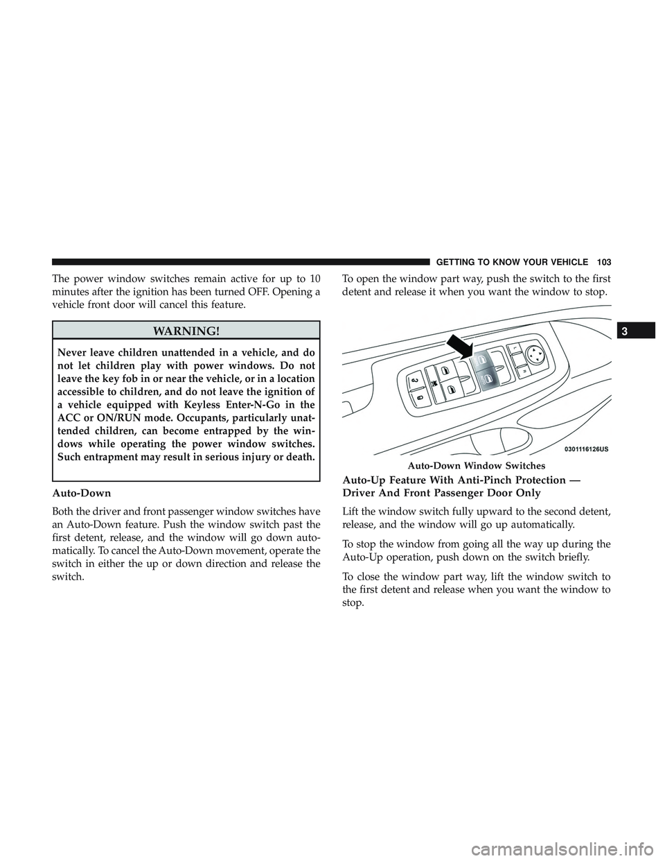
switch.To open the window part way, push the switch to the first
detent and release it when you want the window to stop.
Auto-Up Feature With Anti-Pinch Protection —
Driver And Front Passenger Door Only
Lift the window switch fully upward to the second detent,
release, and the window will go up automatically.
To stop the window from going all the way up during the
Auto-Up operation, push down on the switch briefly.
To close the window part way, lift the window switch to
the first detent and release when you want the window to
stop.
Auto-Down Window Switches
3
GETTING TO KNOW YOUR VEHICLE 103
Page 108 of 592
WARNING!(Continued)
equipped with Keyless Enter-N-Go in the ACC or
ON/RUN mode. Occupants, particularly unattended
children, can become entrapped by the power sun-
roof while operating the power sunroof switch. Such
entrapment may result in serious injury or death.
• In a collision, there is a greater risk of being thrown
from a vehicle with an open sunroof. You could also
be seriously injured or killed. Always fasten your
seat belt properly and make sure all passengers are
also properly secured.
• Do not allow small children to operate the sunroof.
Never allow your fingers, other body parts, or any
object, to project through the sunroof opening. In-
jury may result.
Opening Sunroof
Express
Push the switch rearward and release it within one-half
second. The sunroof and sunshade will open automatically
and stop when the full open position is reached. This is
called “Express Open.” During Express Open operation,
any other actuation of the sunroof switch will stop the
sunroof. Manual Mode
To open the sunroof, push and hold the switch rearward.
The sunroof will move rearward and automatically stop at
full open position. Any release of the switch will stop the
movement. The sunroof and sunshade will remain in a
partially opened condition until the sunroof switch is
pushed again.
Closing Sunroof
Express
Push the switch forward and release it within one-half
second and the sunroof will close automatically from any
position. The sunroof will close fully and stop automati-
cally. This is called “Express Close.” During Express Close
operation, any other actuation of the switch will stop the
sunroof.
Manual Mode
To close the sunroof, push and hold the switch forward.
The sunroof will move forward and automatically stop at
full closed position. Any release of the switch will stop the
movement and the sunroof will remain in a partially closed
condition until the sunroof switch is pushed again.
106 GETTING TO KNOW YOUR VEHICLE
Page 109 of 592
Wind Buffeting
Wind buffeting can be described as the perception of
pressure on the ears or a helicopter-type sound in the ears.
Your vehicle may exhibit wind buffeting with the windows
down, or the sunroof (if equipped) in certain open or
partially open positions. This is a normal occurrence and
can be minimized. If the buffeting occurs with the rear
windows open, then open the front and rear windows
together to minimize the buffeting. If the buffeting occurs
with the sunroof open, adjust the sunroof opening to
minimize the buffeting or open any window.
Sunshade Operation
The sunshade can be opened manually. However, the
sunshade will open automatically as the sunroof opens.
NOTE:The sunshade cannot be closed if the sunroof is
open.
Pinch Protect Feature
This feature will detect an obstruction in the closing of the
sunroof during the Express Close operation. If an obstruc-
tion in the path of the sunroof is detected, the sunroof will
automatically retract. Remove the obstruction if this oc-
curs. NOTE:
If three consecutive sunroof close attempts result in
Pinch Protect reversals, Pinch Protect will disable and the
sunroof must be closed in Manual Mode.
Venting Sunroof — Express
Push and release the Vent button within one half second
and the sunroof will open to the vent position. This is
called “Express Vent”, and it will occur regardless of
sunroof position. During Express Vent operation, any other
actuation of the switch will stop the sunroof.
Sunroof Maintenance
Use only a non-abrasive cleaner and a soft cloth to clean the
glass panel.
Ignition Off Operation
NOTE:
• The power sunroof switch can remain active in Acces-
sory Delay for up to approximately ten minutes after the
vehicle’s ignition is placed to the OFF position. Opening
either front door will cancel this feature.
• This feature is programmable using the Uconnect Sys-
tem. Refer to “Uconnect Settings” in “Multimedia” for
further information.
3
GETTING TO KNOW YOUR VEHICLE 107
Page 118 of 592
2. Place the hand-held transmitter 1 to 3 inches (3 to 8 cm)away from the HomeLink button you wish to program
while keeping the HomeLink indicator light in view.
3. Push and hold the HomeLink button you want to program while you push and hold the hand-held trans-
mitter button.
4. Continue to hold both buttons and observe the indicator light. The HomeLink indicator will flash slowly and
then rapidly after HomeLink has received the frequency
signal from the hand-held transmitter. Release both
buttons after the indicator light changes from slow to
rapid.
5. At the garage door opener motor (in the garage), locate the “LEARN” or “TRAINING” button. This can usually
be found where the hanging antenna wire is attached to
the garage door opener/device motor. Firmly push and
release the “LEARN” or “TRAINING” button. On some
garage door openers/devices there may be a light that
blinks when the garage door opener/device is in the
LEARN/TRAIN mode.
NOTE: You have 30 seconds in which to initiate the next
step after the LEARN button has been pushed. 6. Return to the vehicle and push the programmed
HomeLink button twice (holding the button for two
seconds each time). If the garage door opener/device
activates, programming is complete.
NOTE: If the garage door opener/device does not activate,
push the button a third time (for two seconds) to complete
the training.
To program the remaining two HomeLink buttons, repeat
each step for each remaining button. DO NOT erase the
channels.
Programming A Non-Rolling Code
For programming Garage Door Openers manufactured
before 1995:
1. Place the ignition in the ON/RUN position.
NOTE: For vehicles equipped with Keyless Enter-N-Go,
place the ignition in the RUN position with the engine ON.
Make sure while programming HomeLink with the engine
ON that your vehicle is outside of your garage, or that the
garage door remains open at all times.
2. Place the hand-held transmitter 1 to 3 inches (3 to 8 cm) away from the HomeLink button you wish to program
while keeping the HomeLink indicator light in view.
116 GETTING TO KNOW YOUR VEHICLE
Page 146 of 592
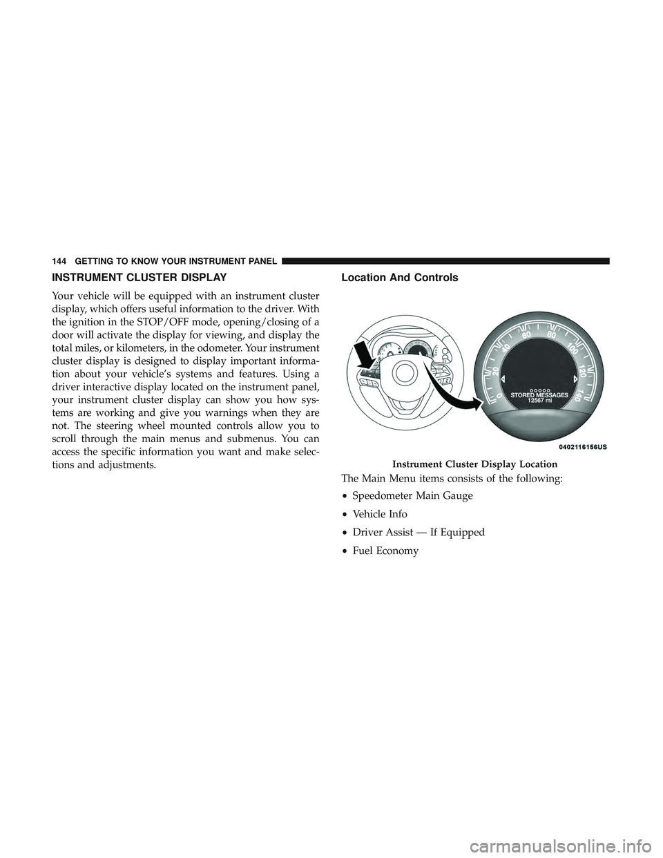
INSTRUMENT CLUSTER DISPLAY
Your vehicle will be equipped with an instrument cluster
display, which offers useful information to the driver. With
the ignition in the STOP/OFF mode, opening/closing of a
door will activate the display for viewing, and display the
total miles, or kilometers, in the odometer. Your instrument
cluster display is designed to display important informa-
tion about your vehicle’s systems and features. Using a
driver interactive display located on the instrument panel,
your instrument cluster display can show you how sys-
tems are working and give you warnings when they are
not. The steering wheel mounted controls allow you to
scroll through the main menus and submenus. You can
access the specific information you want and make selec-
tions and adjustments.
Location And Controls
The Main Menu items consists of the following:
•Speedometer Main Gauge
• Vehicle Info
• Driver Assist — If Equipped
• Fuel Economy
Instrument Cluster Display Location
144 GETTING TO KNOW YOUR INSTRUMENT PANEL
Page 155 of 592
Upper Right
•None
• Compass
• Outside Temp (default setting)
• Time
• Range To Empty (RTE)
• Fuel Economy Average
• Fuel Economy Current
• Trip A
• Trip B
Defaults (Restores All Settings To Default Settings)
• Restore
• Cancel
Battery Saver On/Battery Saver Mode Message —
Electrical Load Reduction Actions — If Equipped
This vehicle is equipped with an Intelligent Battery Sensor
(IBS) to perform additional monitoring of the electrical
system and status of the vehicle battery. In cases when the IBS detects charging system failure, or
the vehicle battery conditions are deteriorating, electrical
load reduction actions will take place to extend the driving
time and distance of the vehicle. This is done by reducing
power to or turning off non-essential electrical loads.
Load reduction is only active when the engine is running.
It will display a message if there is a risk of battery
depletion to the point where the vehicle may stall due to
lack of electrical supply, or will not restart after the current
drive cycle.
When load reduction is activated, the message “Battery
Saver On” or “Battery Saver Mode” will appear in the
instrument cluster.
These messages indicate the vehicle battery has a low state
of charge and continues to lose electrical charge at a rate
that the charging system cannot sustain.
4
GETTING TO KNOW YOUR INSTRUMENT PANEL 153