DODGE DURANGO 2018 Repair Manual
Manufacturer: DODGE, Model Year: 2018, Model line: DURANGO, Model: DODGE DURANGO 2018Pages: 592, PDF Size: 6.57 MB
Page 61 of 592
WARNING!(Continued)
position the seat will not provide the proper stability
for child seats and/or passengers. An improperly
latched seat could cause serious injury.
Folding Third Row
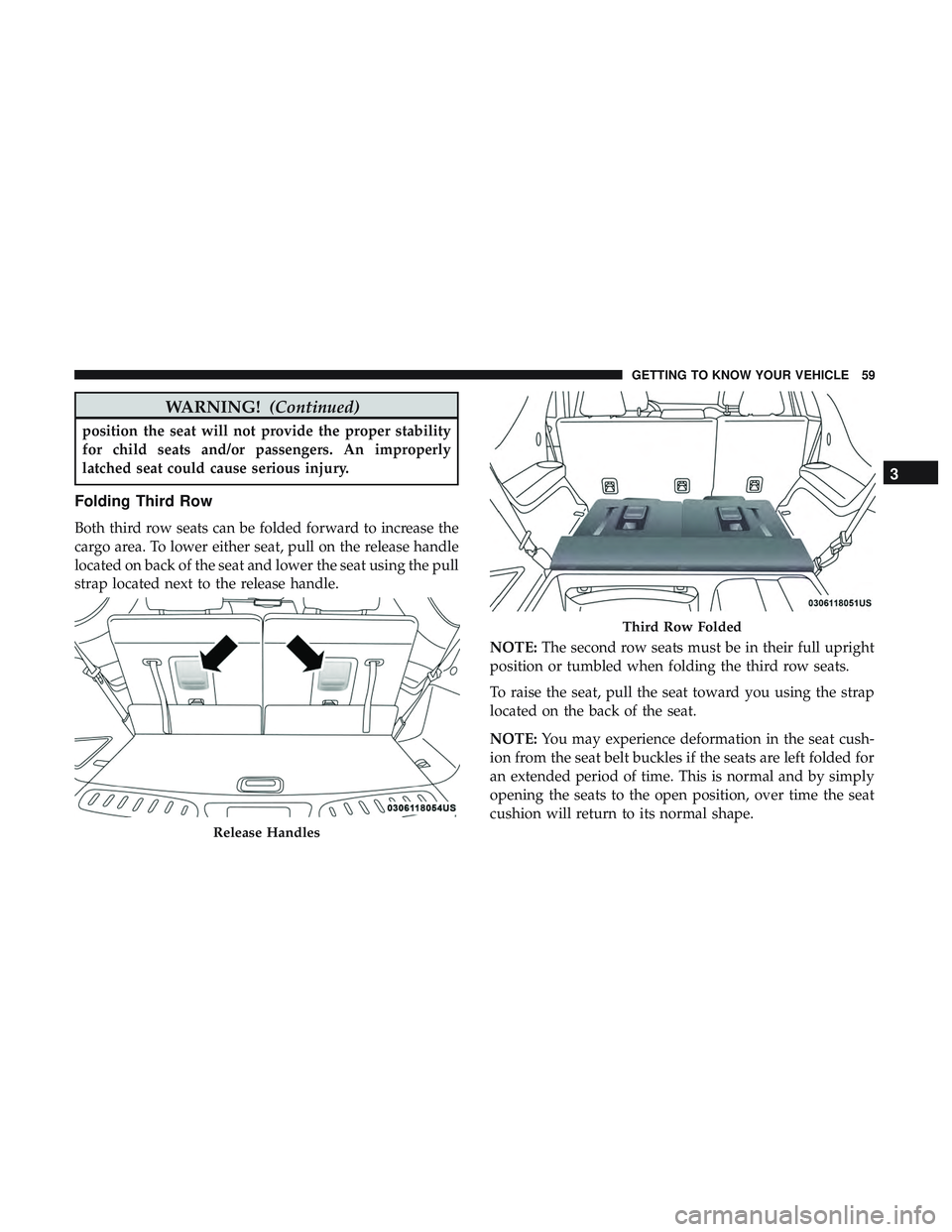
Both third row seats can be folded forward to increase the
cargo area. To lower either seat, pull on the release handle
located on back of the seat and lower the seat using the pull
strap located next to the release handle.
NOTE:The second row seats must be in their full upright
position or tumbled when folding the third row seats.
To raise the seat, pull the seat toward you using the strap
located on the back of the seat.
NOTE: You may experience deformation in the seat cush-
ion from the seat belt buckles if the seats are left folded for
an extended period of time. This is normal and by simply
opening the seats to the open position, over time the seat
cushion will return to its normal shape.
Release Handles
Third Row Folded
3
GETTING TO KNOW YOUR VEHICLE 59
Page 62 of 592
WARNING!
Be certain that the seatback is securely locked into
position. If the seatback is not securely locked into
position the seat will not provide the proper stability
for child seats and/or passengers. An improperly
latched seat could cause serious injury.
HEAD RESTRAINTS
Head restraints are designed to reduce the risk of injury by
restricting head movement in the event of a rear impact.
Head restraints should be adjusted so that the top of the
head restraint is located above the top of your ear.
WARNING!
•All occupants, including the driver, should not oper-
ate a vehicle or sit in a vehicle’s seat until the head
restraints are placed in their proper positions in
order to minimize the risk of neck injury in the event
of a crash.
• Head restraints should never be adjusted while the
vehicle is in motion. Driving a vehicle with the head
restraints improperly adjusted or removed could
(Continued)
WARNING! (Continued)
cause serious injury or death in the event of a
collision.
Supplemental Active Head Restraints — Front
Seats
Active Head Restraints are passive, deployable compo-
nents, and vehicles with this equipment cannot be readily
identified by any markings, only through visual inspection
of the head restraint. The Active Head Restraints (AHR)
will be split in two halves, with the front half being soft
foam and trim, the back half being decorative plastic.
When AHRs deploy during a rear impact, the front half of
the head restraint extends forward to reduce the gap
between the back of the occupant’s head and the AHR. This
system is design to reduce the risk of injury to the driver or
front passenger in certain types of rear impacts. Refer to
“Occupant Restraints” in “Safety” for further information.
To raise the head restraint, pull upward on the head
restraint. To lower the head restraint, push the adjustment
button, located at the base of the head restraint, and push
downward on the head restraint.
60 GETTING TO KNOW YOUR VEHICLE
Page 63 of 592
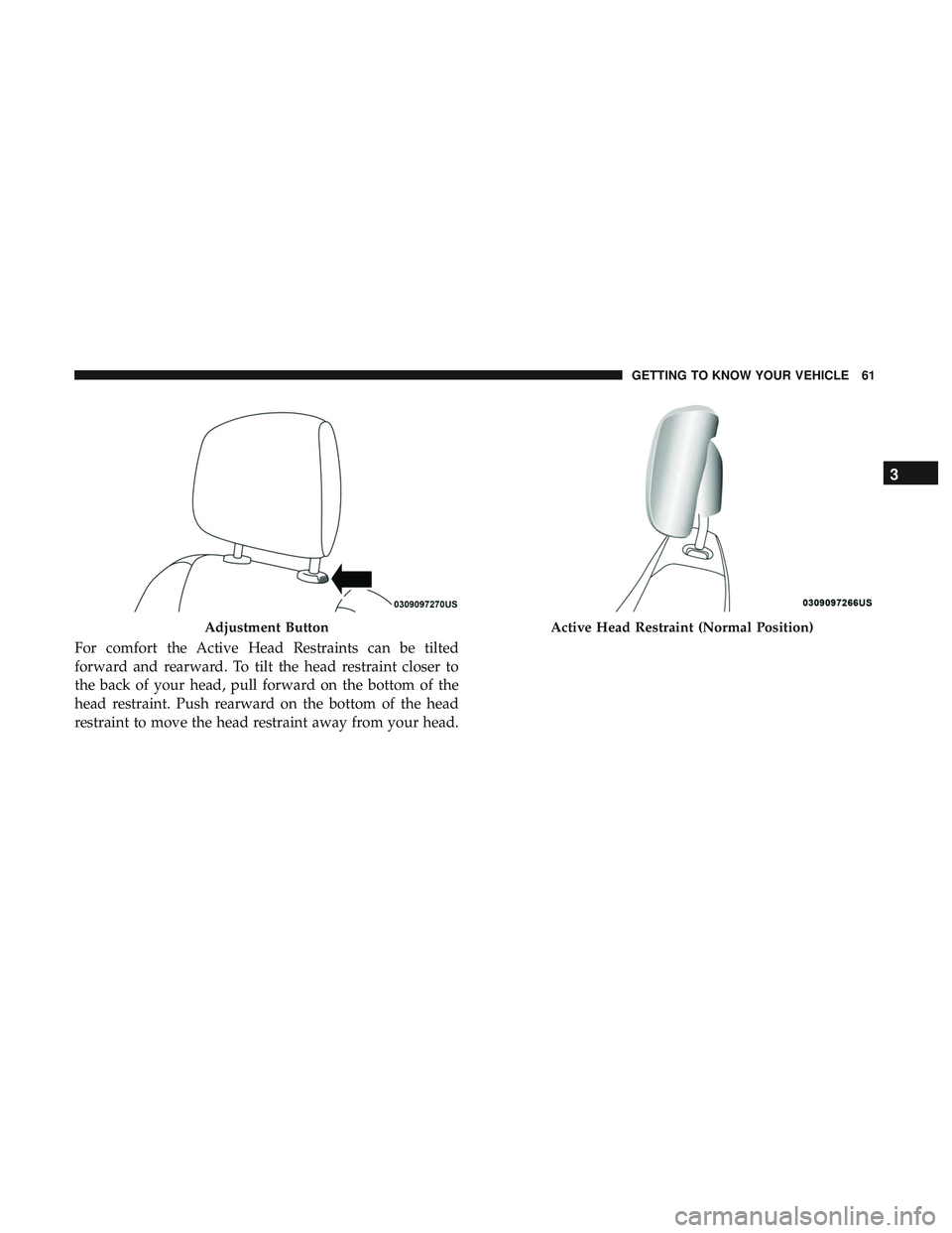
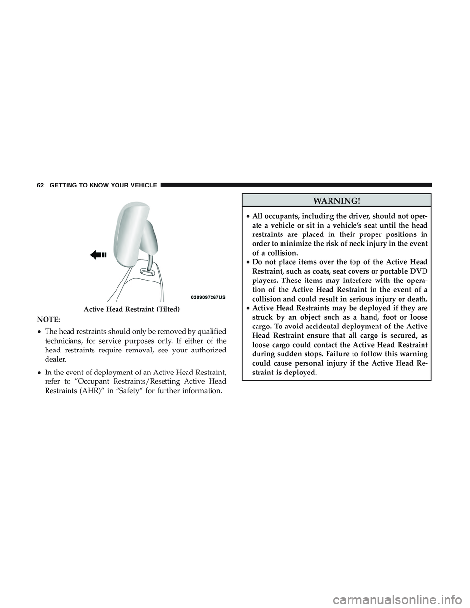
For comfort the Active Head Restraints can be tilted
forward and rearward. To tilt the head restraint closer to
the back of your head, pull forward on the bottom of the
head restraint. Push rearward on the bottom of the head
restraint to move the head restraint away from your head.
Adjustment ButtonActive Head Restraint (Normal Position)
3
GETTING TO KNOW YOUR VEHICLE 61
Page 64 of 592
NOTE:
•The head restraints should only be removed by qualified
technicians, for service purposes only. If either of the
head restraints require removal, see your authorized
dealer.
• In the event of deployment of an Active Head Restraint,
refer to “Occupant Restraints/Resetting Active Head
Restraints (AHR)” in “Safety” for further information.
WARNING!
•All occupants, including the driver, should not oper-
ate a vehicle or sit in a vehicle’s seat until the head
restraints are placed in their proper positions in
order to minimize the risk of neck injury in the event
of a collision.
• Do not place items over the top of the Active Head
Restraint, such as coats, seat covers or portable DVD
players. These items may interfere with the opera-
tion of the Active Head Restraint in the event of a
collision and could result in serious injury or death.
• Active Head Restraints may be deployed if they are
struck by an object such as a hand, foot or loose
cargo. To avoid accidental deployment of the Active
Head Restraint ensure that all cargo is secured, as
loose cargo could contact the Active Head Restraint
during sudden stops. Failure to follow this warning
could cause personal injury if the Active Head Re-
straint is deployed.
Active Head Restraint (Tilted)
62 GETTING TO KNOW YOUR VEHICLE
Page 65 of 592
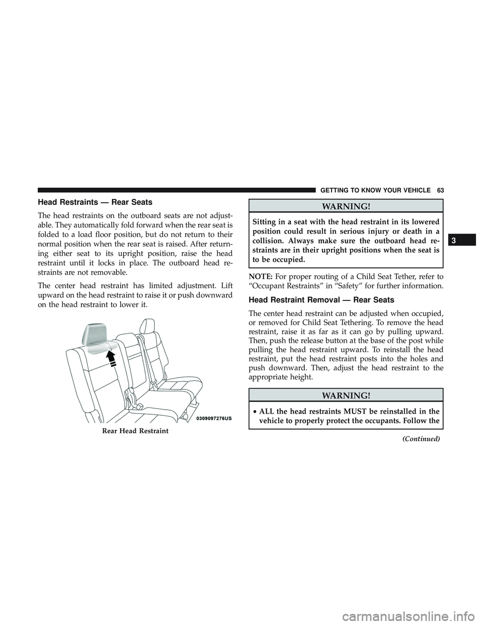
Head Restraints — Rear Seats
The head restraints on the outboard seats are not adjust-
able. They automatically fold forward when the rear seat is
folded to a load floor position, but do not return to their
normal position when the rear seat is raised. After return-
ing either seat to its upright position, raise the head
restraint until it locks in place. The outboard head re-
straints are not removable.
The center head restraint has limited adjustment. Lift
upward on the head restraint to raise it or push downward
on the head restraint to lower it.
WARNING!
Sitting in a seat with the head restraint in its lowered
position could result in serious injury or death in a
collision. Always make sure the outboard head re-
straints are in their upright positions when the seat is
to be occupied.
NOTE: For proper routing of a Child Seat Tether, refer to
“Occupant Restraints” in “Safety” for further information.
Head Restraint Removal — Rear Seats
The center head restraint can be adjusted when occupied,
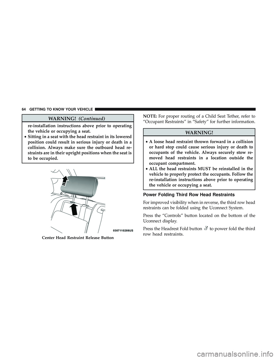
or removed for Child Seat Tethering. To remove the head
restraint, raise it as far as it can go by pulling upward.
Then, push the release button at the base of the post while
pulling the head restraint upward. To reinstall the head
restraint, put the head restraint posts into the holes and
push downward. Then, adjust the head restraint to the
appropriate height.
WARNING!
• ALL the head restraints MUST be reinstalled in the
vehicle to properly protect the occupants. Follow the
(Continued)
Rear Head Restraint
3
GETTING TO KNOW YOUR VEHICLE 63
Page 66 of 592
WARNING!(Continued)
re-installation instructions above prior to operating
the vehicle or occupying a seat.
• Sitting in a seat with the head restraint in its lowered
position could result in serious injury or death in a
collision. Always make sure the outboard head re-
straints are in their upright positions when the seat is
to be occupied. NOTE:
For proper routing of a Child Seat Tether, refer to
“Occupant Restraints” in “Safety” for further information.
WARNING!
• A loose head restraint thrown forward in a collision
or hard stop could cause serious injury or death to
occupants of the vehicle. Always securely stow re-
moved head restraints in a location outside the
occupant compartment.
• ALL the head restraints MUST be reinstalled in the
vehicle to properly protect the occupants. Follow the
re-installation instructions above prior to operating
the vehicle or occupying a seat.
Power Folding Third Row Head Restraints
For improved visibility when in reverse, the third row head
restraints can be folded using the Uconnect System.
Press the “Controls” button located on the bottom of the
Uconnect display.
Press the Headrest Fold button
to power fold the third
row head restraints.
Center Head Restraint Release Button
64 GETTING TO KNOW YOUR VEHICLE
Page 67 of 592
NOTE:
•The head restraints can only be folded downward using
the Headrest Fold button. The head restraints must be
raised manually when occupying the third row.
• Do not fold if there are passengers seated in the third
row seats.
STEERING WHEEL
Manual Tilt/Telescoping Steering Column — If
Equipped
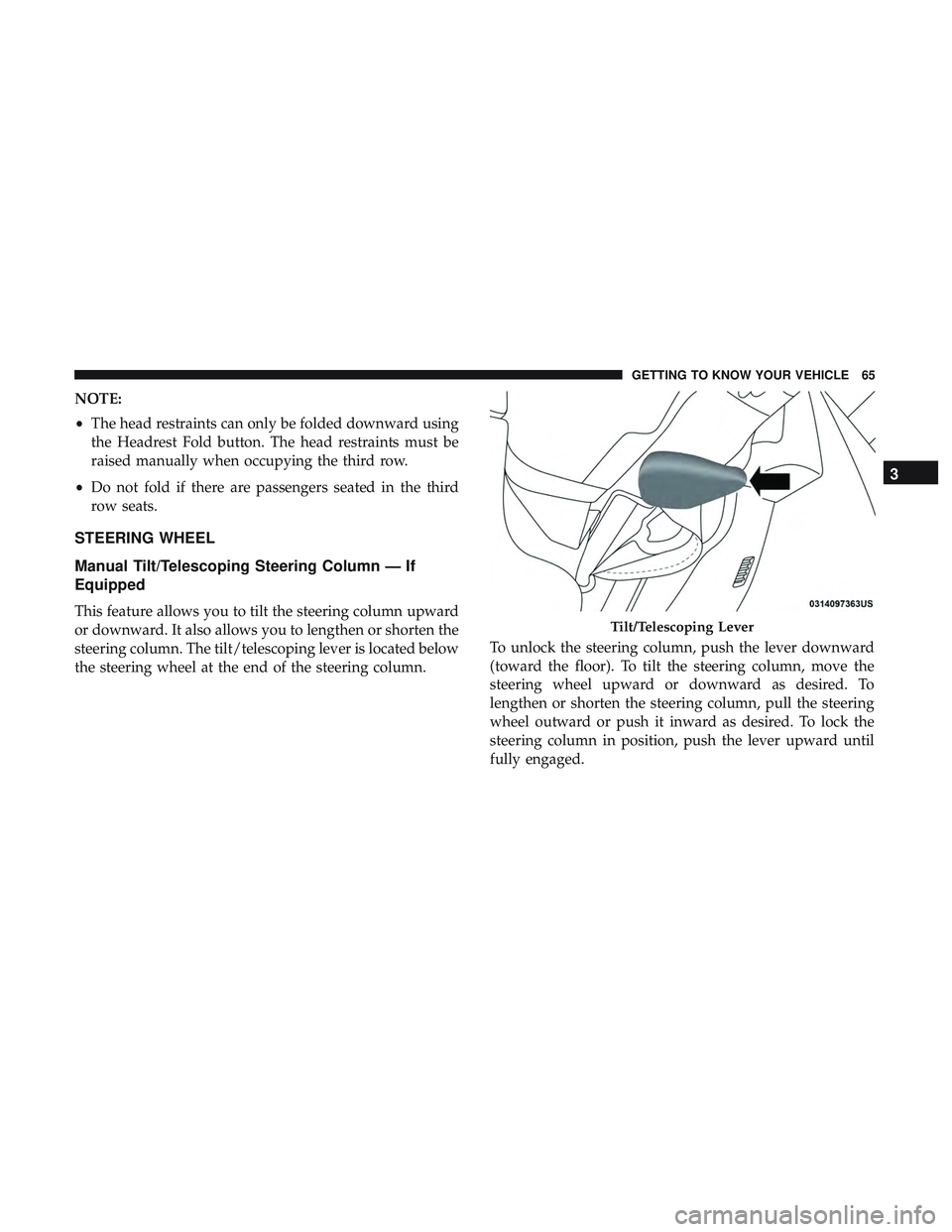
This feature allows you to tilt the steering column upward
or downward. It also allows you to lengthen or shorten the
steering column. The tilt/telescoping lever is located below
the steering wheel at the end of the steering column. To unlock the steering column, push the lever downward
(toward the floor). To tilt the steering column, move the
steering wheel upward or downward as desired. To
lengthen or shorten the steering column, pull the steering
wheel outward or push it inward as desired. To lock the
steering column in position, push the lever upward until
fully engaged.Tilt/Telescoping Lever
3
GETTING TO KNOW YOUR VEHICLE 65
Page 68 of 592
WARNING!
Do not adjust the steering column while driving.
Adjusting the steering column while driving or driv-
ing with the steering column unlocked, could cause the
driver to lose control of the vehicle. Failure to follow
this warning may result in serious injury or death.
Power Tilt/Telescoping Steering Column — If
Equipped
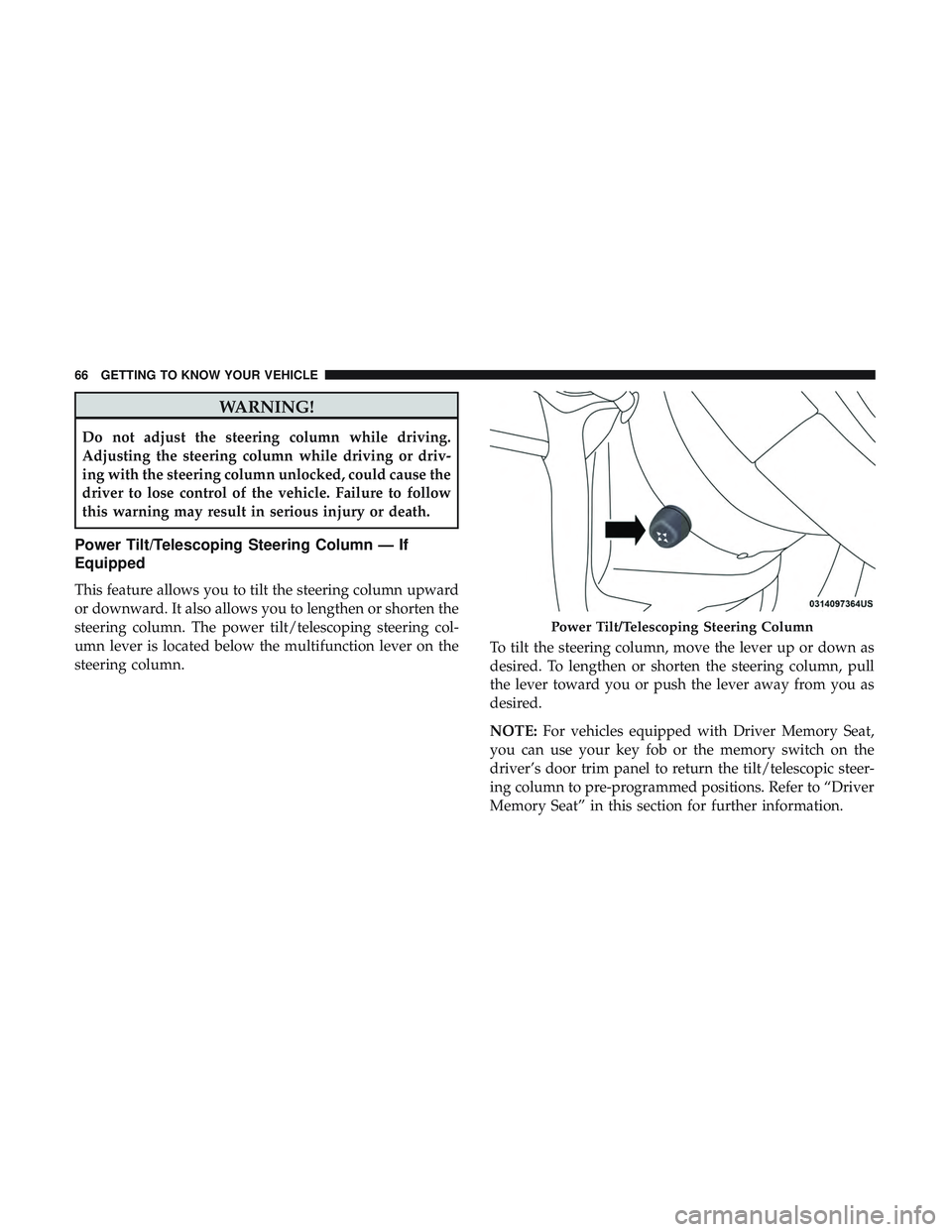
This feature allows you to tilt the steering column upward
or downward. It also allows you to lengthen or shorten the
steering column. The power tilt/telescoping steering col-
umn lever is located below the multifunction lever on the
steering column.To tilt the steering column, move the lever up or down as
desired. To lengthen or shorten the steering column, pull
the lever toward you or push the lever away from you as
desired.
NOTE:
For vehicles equipped with Driver Memory Seat,
you can use your key fob or the memory switch on the
driver’s door trim panel to return the tilt/telescopic steer-
ing column to pre-programmed positions. Refer to “Driver
Memory Seat” in this section for further information.
Power Tilt/Telescoping Steering Column
66 GETTING TO KNOW YOUR VEHICLE
Page 69 of 592
WARNING!
Do not adjust the steering column while driving.
Adjusting the steering column while driving or driv-
ing with the steering column unlocked, could cause the
driver to lose control of the vehicle. Failure to follow
this warning may result in serious injury or death.
Heated Steering Wheel — If Equipped
The steering wheel contains a heating element that helps
warm your hands in cold weather. The heated steering
wheel has only one temperature setting. Once the heated
steering wheel has been turned on, it will stay on for an
average of 80 minutes or more before automatically shut-
ting off. This time will vary based on environmental
temperatures. The heated steering wheel can shut off early
or may not turn on when the steering wheel is already
warm.
The heated steering wheel control button is located within
the Uconnect system. You can gain access to the control
button through the climate screen or the controls screen.
•Press the heated steering wheel button
once to turn
the heating element on.
• Press the heated steering wheel buttona second time
to turn the heating element off.
NOTE: The engine must be running for the heated steering
wheel to operate.
Vehicles Equipped With Remote Start
On models that are equipped with remote start, the heated
steering wheel can be programmed to come on during a
remote start through the Uconnect system. Refer to
“Uconnect Settings” in “Multimedia” for further informa-
tion.
WARNING!
• Persons who are unable to feel pain to the skin
because of advanced age, chronic illness, diabetes,
spinal cord injury, medication, alcohol use, exhaus-
tion, or other physical conditions must exercise care
when using the steering wheel heater. It may cause
burns even at low temperatures, especially if used
for long periods.
• Do not place anything on the steering wheel that
insulates against heat, such as a blanket or steering
wheel covers of any type and material. This may
cause the steering wheel heater to overheat.
3
GETTING TO KNOW YOUR VEHICLE 67
Page 70 of 592
MIRRORS
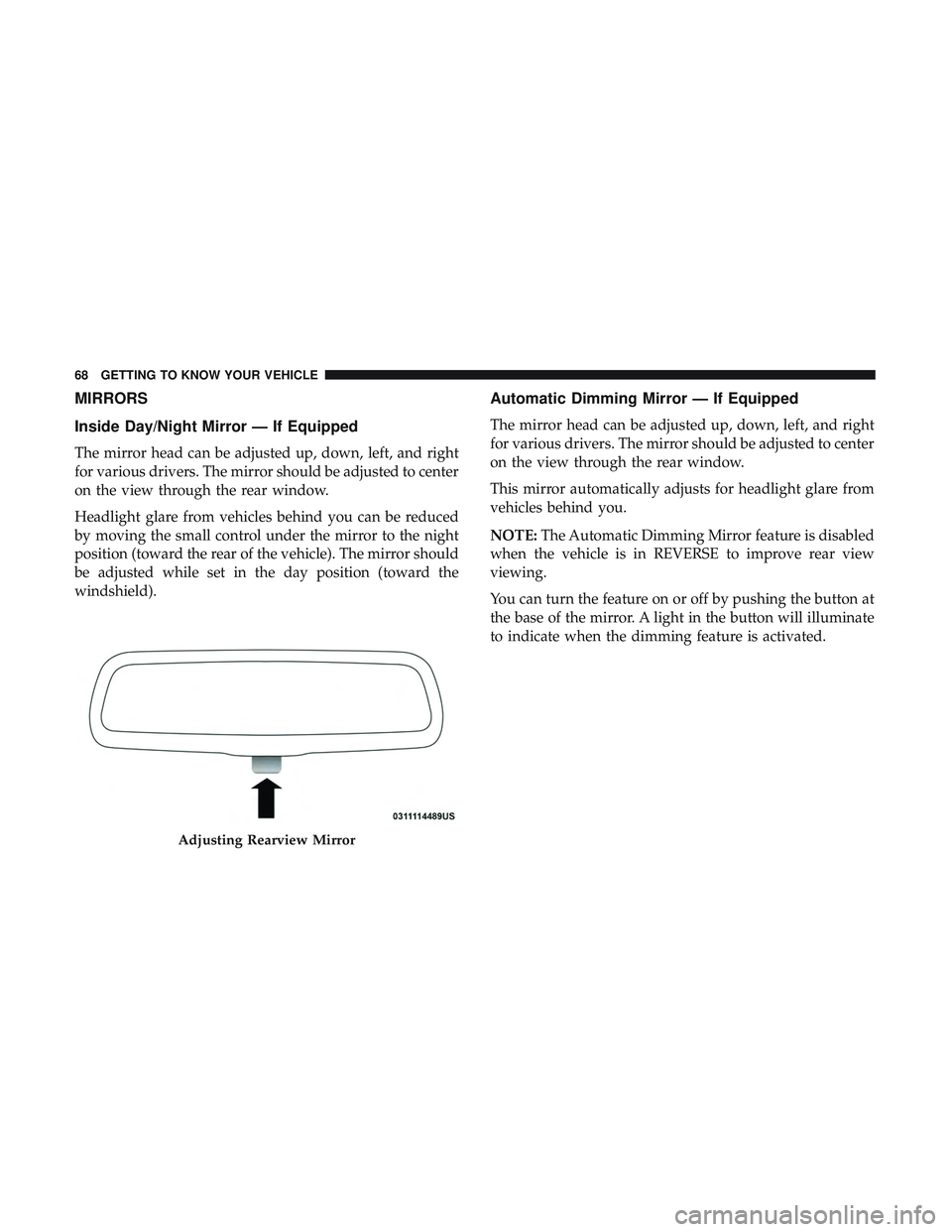
Inside Day/Night Mirror — If Equipped
The mirror head can be adjusted up, down, left, and right
for various drivers. The mirror should be adjusted to center
on the view through the rear window.
Headlight glare from vehicles behind you can be reduced
by moving the small control under the mirror to the night
position (toward the rear of the vehicle). The mirror should
be adjusted while set in the day position (toward the
windshield).
Automatic Dimming Mirror — If Equipped
The mirror head can be adjusted up, down, left, and right
for various drivers. The mirror should be adjusted to center
on the view through the rear window.
This mirror automatically adjusts for headlight glare from
vehicles behind you.
NOTE:The Automatic Dimming Mirror feature is disabled
when the vehicle is in REVERSE to improve rear view
viewing.
You can turn the feature on or off by pushing the button at
the base of the mirror. A light in the button will illuminate
to indicate when the dimming feature is activated.
Adjusting Rearview Mirror
68 GETTING TO KNOW YOUR VEHICLE