stop start DODGE DURANGO 2019 Workshop Manual
[x] Cancel search | Manufacturer: DODGE, Model Year: 2019, Model line: DURANGO, Model: DODGE DURANGO 2019Pages: 598, PDF Size: 4.32 MB
Page 355 of 598
•Check for signs of tire wear or visible tire damage before
towing a trailer. Refer to “Tires” in “Servicing And
Maintenance” for the proper inspection procedure.
• When replacing tires, refer to “Tires” in “Servicing And
Maintenance” for the proper tire replacement proce-
dures. Replacing tires with a higher load carrying capac-
ity will not increase the vehicle’s GVWR and GAWR
limits.
Towing Requirements — Trailer Brakes
•Do not interconnect the hydraulic brake system or
vacuum system of your vehicle with that of the trailer.
This could cause inadequate braking and possible per-
sonal injury.
• An electronically actuated trailer brake controller is
required when towing a trailer with electronically actu-
ated brakes. When towing a trailer equipped with a
hydraulic surge actuated brake system, an electronic
brake controller is not required.
• Trailer brakes are recommended for trailers over
1,000 lbs (453 kg) and required for trailers in excess of
2,000 lbs (907 kg).
WARNING!
•Do not connect trailer brakes to your vehicle’s hy-
draulic brake lines. It can overload your brake sys-
tem and cause it to fail. You might not have brakes
when you need them and could have an accident.
• Towing any trailer will increase your stopping dis-
tance. When towing, you should allow for additional
space between your vehicle and the vehicle in front
of you. Failure to do so could result in an accident.
CAUTION!
If the trailer weighs more than 1,000 lbs (453 kg)
loaded, it should have its own brakes and they should
be of adequate capacity. Failure to do this could lead to
accelerated brake lining wear, higher brake pedal
effort, and longer stopping distances.
Integrated Trailer Brake Module — If Equipped
Your vehicle may have an Integrated Trailer Brake Module
(ITBM) for Electric and Electric Over Hydraulic (EOH)
trailer brakes.
6
STARTING AND OPERATING 353
Page 358 of 598
Repeat steps 8 and 9 until the GAIN setting is at a point just
below trailer wheel lockup. If towing a heavier trailer,
trailer wheel lockup may not be attainable even with the
maximum GAIN setting of 10.
Display Messages
The trailer brake control interacts with the instrument
cluster display. Display messages, along with a single
chime, will be displayed when a malfunction is determined
in the trailer connection, trailer brake control, or on the
trailer. Refer to “Instrument Cluster Display” in “Getting
To Know Your Instrument Panel” for further information.
WARNING!
Connecting a trailer that is not compatible with the
ITBM system may result in reduced or complete loss of
trailer braking. There may be a increase in stopping
distance or trailer instability which could result in
personal injury.
CAUTION!
Connecting a trailer that is not compatible with the
ITBM system may result in reduced or complete loss of
trailer braking. There may be a increase in stopping
distance or trailer instability which could result in
damage to your vehicle, trailer, or other property.
NOTE:
• An aftermarket controller may be available for use with
trailers with air or electric-over-hydraulic trailer brake
systems. To determine the type of brakes on your trailer
and the availability of controllers, check with your
trailer manufacturer or dealer.
• Removal of the ITBM will cause errors and it may cause
damage to the electrical system and electronic modules
of the vehicle. See your authorized dealer if an aftermar-
ket module is to be installed.
Towing Requirements — Trailer Lights And Wiring
Whenever you pull a trailer, regardless of the trailer size,
stoplights and turn signals on the trailer are required for
motoring safety.
356 STARTING AND OPERATING
Page 359 of 598
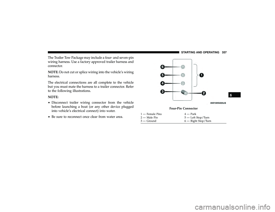
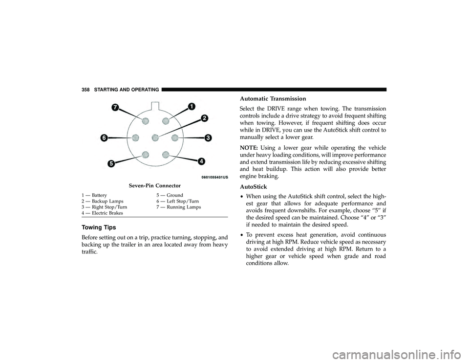
The Trailer Tow Package may include a four- and seven-pin
wiring harness. Use a factory approved trailer harness and
connector.
NOTE:Do not cut or splice wiring into the vehicle’s wiring
harness.
The electrical connections are all complete to the vehicle
but you must mate the harness to a trailer connector. Refer
to the following illustrations.
NOTE:
• Disconnect trailer wiring connector from the vehicle
before launching a boat (or any other device plugged
into vehicle’s electrical connect) into water.
• Be sure to reconnect once clear from water area.
Four-Pin Connector
1 — Female Pins 4 — Park
2 — Male Pin 5 — Left Stop/Turn
3 — Ground 6 — Right Stop/Turn
6
STARTING AND OPERATING 357
Page 360 of 598
Towing Tips
Before setting out on a trip, practice turning, stopping, and
backing up the trailer in an area located away from heavy
traffic.
Automatic Transmission
Select the DRIVE range when towing. The transmission
controls include a drive strategy to avoid frequent shifting
when towing. However, if frequent shifting does occur
while in DRIVE, you can use the AutoStick shift control to
manually select a lower gear.
NOTE:Using a lower gear while operating the vehicle
under heavy loading conditions, will improve performance
and extend transmission life by reducing excessive shifting
and heat buildup. This action will also provide better
engine braking.
AutoStick
• When using the AutoStick shift control, select the high-
est gear that allows for adequate performance and
avoids frequent downshifts. For example, choose “5” if
the desired speed can be maintained. Choose “4” or “3”
if needed to maintain the desired speed.
• To prevent excess heat generation, avoid continuous
driving at high RPM. Reduce vehicle speed as necessary
to avoid extended driving at high RPM. Return to a
higher gear or vehicle speed when grade and road
conditions allow.
Seven-Pin Connector
1 — Battery 5 — Ground
2 — Backup Lamps 6 — Left Stop/Turn
3 — Right Stop/Turn 7 — Running Lamps
4 — Electric Brakes 358 STARTING AND OPERATING
Page 361 of 598
Speed Control — If Equipped
•Do not use on hilly terrain or with heavy loads.
• When using the speed control, if you experience speed
drops greater than 10 mph (16 km/h), disengage until
you can get back to cruising speed.
• Use speed control in flat terrain and with light loads to
maximize fuel efficiency.
Cooling System
To reduce potential for engine and transmission overheat-
ing, take the following actions:
City Driving
•In city traffic — while stopped, place the transmission in
NEUTRAL, but do not increase engine idle speed.
Highway Driving
• Reduce speed.
• Temporarily turn off air conditioning.
SNOW PLOW
Snow plows, winches, and other aftermarket equipment
should notbe added to the front end of your vehicle. The
airbag crash sensors may be affected by the change in the
front end structure. The airbags could deploy unexpectedly
or could fail to deploy during a collision.
WARNING!
Do not add a snow plow, winches, or any other
aftermarket equipment to the front of your vehicle.
This could adversely affect the functioning of the
airbag system and you could be injured.6
STARTING AND OPERATING 359
Page 365 of 598
CAUTION!
It is necessary to follow these steps to be certain that
the transfer case is fully in NEUTRAL (N) before
recreational towing to prevent damage to internal
parts.
1. Bring the vehicle to a complete stop on level ground, with the engine running.
2. Press and hold the brake pedal.
3. Shift the transmission into NEUTRAL.
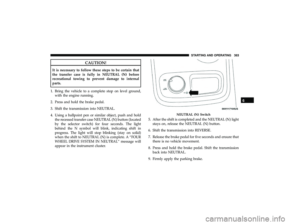
4. Using a ballpoint pen or similar object, push and hold the recessed transfer case NEUTRAL (N) button (located
by the selector switch) for four seconds. The light
behind the N symbol will blink, indicating shift in
progress. The light will stop blinking (stay on solid)
when the shift to NEUTRAL (N) is complete. A “FOUR
WHEEL DRIVE SYSTEM IN NEUTRAL” message will
appear in the instrument cluster. 5. After the shift is completed and the NEUTRAL (N) light
stays on, release the NEUTRAL (N) button.
6. Shift the transmission into REVERSE.
7. Release the brake pedal for five seconds and ensure that there is no vehicle movement.
8. Press and hold the brake pedal. Shift the transmission back into NEUTRAL.
9. Firmly apply the parking brake.
NEUTRAL (N) Switch
6
STARTING AND OPERATING 363
Page 366 of 598
10. With the transmission and transfer case in NEUTRAL,push and hold the ENGINE START/STOP button until
the engine turns off.
11. Place the transmission gear selector in PARK. Release the brake pedal.
12. Push the ENGINE STOP/START button twice (without pressing the brake pedal) to turn the ignition to the
OFF mode.
CAUTION!
Damage to the transmission may occur if the transmis-
sion is shifted into PARK with the transfer case in
NEUTRAL (N) and the engine running. With the
transfer case in NEUTRAL (N) ensure that the engine
is OFF before shifting the transmission into PARK.
13. Attach the vehicle to the tow vehicle using a suitable tow bar.
14. Release the parking brake. NOTE:
•
Steps 1 through 3 are requirements that must be met
before pushing the NEUTRAL (N) button, and must
continue to be met until the shift has been completed. If
any of these requirements are not met before pushing
the NEUTRAL (N) button or are no longer met during
the shift, the NEUTRAL (N) indicator light will flash
continuously until all requirements are met or until the
NEUTRAL (N) button is released.
• The ignition must be in the ON/RUN mode for a shift to
take place and for the position indicator lights to be
operable. If the ignition is not in the ON/RUN mode, the
shift will not take place and no position indicator lights
will be on or flashing.
• A flashing NEUTRAL (N) position indicator light indi-
cates that shift requirements have not been met.
Shifting Out Of NEUTRAL (N)
Use the following procedure to prepare your vehicle for
normal usage.
1. Bring the vehicle to a complete stop, leaving it con-
nected to the tow vehicle.
2. Firmly apply the parking brake.
364 STARTING AND OPERATING
Page 370 of 598
Standing Water
Avoid driving in standing water deeper than 20 inches
(51 cm), and reduce speed appropriately to minimize wave
effects. Maximum speed in 20 inches (51 cm) of water is
less than 5 mph (8 km/h).
Maintenance
After driving through deep water, inspect your vehicle
fluids and lubricants (engine oil, transmission oil, axle,
transfer case) to assure the fluids have not been contami-
nated. Contaminated fluid (milky, foamy in appearance)
should be flushed/changed as soon as possible to prevent
component damage.
Driving In Snow, Mud And Sand
In heavy snow, when pulling a load, or for additional
control at slower speeds, shift the transmission to a low
gear and shift the transfer case to LOW if necessary. Refer
to “All-Wheel Drive Operation” in “Starting And Operat-
ing” for further information. Do not shift to a lower gear
than necessary to maintain forward motion. Over-revving
the engine can spin the wheels and traction will be lost.
Avoid abrupt downshifts on icy or slippery roads, because
engine braking may cause skidding and loss of control.
Hill Climbing
NOTE:Before attempting to climb a hill, determine the
conditions at the crest and/or on the other side.
Before climbing a steep hill, shift the transmission to a
lower gear and shift the transfer case to LOW. Use first gear
and LOW for very steep hills.
If you stall or begin to lose forward motion while climbing
a steep hill, allow your vehicle to come to a stop and
immediately apply the brakes. Restart the engine, and shift
into REVERSE. Back slowly down the hill, allowing the
compression braking of the engine to help regulate your
speed. If the brakes are required to control vehicle speed,
apply them lightly and avoid locking or skidding the tires.
WARNING!
If the engine stalls, you lose forward motion, or cannot
make it to the top of a steep hill or grade, never attempt
to turn around. To do so may result in tipping and
rolling the vehicle. Always back carefully straight
down a hill in REVERSE gear. Never back down a hill
in NEUTRAL using only the brake.
Remember, never drive diagonally across a hill; always
drive straight up or down.
368 STARTING AND OPERATING
Page 403 of 598

WARNING!
A loose tire or jack thrown forward in a collision or
hard stop, could endanger the occupants of the vehicle.
Always stow the jack parts and the spare tire in the
places provided.
Road Tire Installation
1. Mount the road tire on the axle.
2. Install the remaining lug nuts with the cone shaped endof the nut toward the wheel. Lightly tighten the lug
nuts.
WARNING!
To avoid the risk of forcing the vehicle off the jack, do
not tighten the wheel nuts fully until the vehicle has
been lowered. Failure to follow this warning may
result in serious injury.
3. Lower the vehicle to the ground by turning the jack handle counterclockwise.
4. Refer to “Torque Specifications” in “Technical Specifica- tions” for proper lug nut torque. 5. After 25 miles (40 km), check the lug nut torque with a
torque wrench to ensure that all lug nuts are properly
seated against the wheel.
JUMP STARTING
If your vehicle has a discharged battery, it can be jump
started using a set of jumper cables and a battery in another
vehicle, or by using a portable battery booster pack. Jump
starting can be dangerous if done improperly, so please
follow the procedures in this section carefully.
WARNING!
Do not attempt jump starting if the battery is frozen. It
could rupture or explode and cause personal injury.
CAUTION!
Do not use a portable battery booster pack or any other
booster source with a system voltage greater than 12
Volts or damage to the battery, starter motor, alternator
or electrical system may occur.
NOTE: When using a portable battery booster pack, follow
the manufacturer’s operating instructions and precautions.
7
IN CASE OF EMERGENCY 401
Page 406 of 598
5. Start the engine in the vehicle that has the boosterbattery, let the engine idle a few minutes, and then start
the engine in the vehicle with the discharged battery.
CAUTION!
Do not run the booster vehicle engine above 2,000 rpm
since it provides no charging benefit, wastes fuel, and
can damage booster vehicle engine.
6. Once the engine is started, remove the jumper cables in the reverse sequence:
Disconnecting The Jumper Cables
1. Disconnect the negative (-)end of the jumper cable from
the remote negative (-)post of the discharged vehicle.
2. Disconnect the opposite end of the negative (-)jumper
cable from the negative (-)post of the booster battery.
3. Disconnect the positive (+)end of the jumper cable from
the positive (+)post of the booster battery.
4. Disconnect the opposite end of the positive (+)jumper
cable from the remote positive (+)post of the discharged
vehicle. 5. Reinstall the protective cover over the remote positive
(+) post of the discharged vehicle.
If frequent jump starting is required to start your vehicle
you should have the battery and charging system tested at
an authorized dealer.CAUTION!
Accessories plugged into the vehicle power outlets
draw power from the vehicle’s battery, even when not
in use (i.e., cellular devices, etc.). Eventually, if plugged
in long enough without engine operation, the vehicle’s
battery will discharge sufficiently to degrade battery
life and/or prevent the engine from starting.
IF YOUR ENGINE OVERHEATS
In any of the following situations, you can reduce the
potential for overheating by taking the appropriate action.
• On the highways — slow down.
• In city traffic — while stopped, place the transmission in
NEUTRAL, but do not increase the engine idle speed
while preventing vehicle motion with the brakes.
404 IN CASE OF EMERGENCY