brake controller DODGE DURANGO 2019 Owners Manual
[x] Cancel search | Manufacturer: DODGE, Model Year: 2019, Model line: DURANGO, Model: DODGE DURANGO 2019Pages: 598, PDF Size: 4.32 MB
Page 180 of 598
For vehicles not equipped with an instrument cluster
display, perform the following steps:
1. Center the steering wheel (front wheels pointingstraight forward).
2. Shift the transmission into PARK.
3. Apply the parking brake.
4. Start the engine.
5. Rotate the steering wheel slightly more than one-half turn to the left.
6. Push the “ESC Off” button located in the lower switch bank below the climate control four times within 20
seconds. The “ESC Off Indicator Light” should turn on
and turn off two times.
7. Rotate the steering wheel back to center and then an additional slightly more than one-half turn to the right.
8. Turn the ignition to the OFF mode and then back to ON. If the sequence was completed properly, the “ESC Off
Indicator Light” will blink several times to confirm HSA
is disabled.
9. Repeat these steps if you want to return this feature to its previous setting.Towing With HSA
HSA will also provide assistance to mitigate roll back while
towing a trailer.
WARNING!
•If you use a trailer brake controller with your trailer,
the trailer brakes may be activated and deactivated
with the brake switch. If so, there may not be enough
brake pressure to hold both the vehicle and the
trailer on a hill when the brake pedal is released. In
order to avoid rolling down an incline while resum-
ing acceleration, manually activate the trailer brake
or apply more vehicle brake pressure prior to releas-
ing the brake pedal.
• HSA is not a parking brake. Always apply the
parking brake fully when exiting your vehicle. Also,
be certain to place the transmission in PARK.
• Failure to follow these warnings can result in a
collision or serious personal injury.
178 SAFETY
Page 193 of 598
1. This device may not cause harmful interference.
2. This device must accept any interference received, in-cluding interference that may cause undesired opera-
tion.
NOTE: Changes or modifications not expressly approved
by the party responsible for compliance could void the
user ’s authority to operate the equipment.
Forward Collision Warning (FCW) With Mitigation
The Forward Collision Warning (FCW) with Mitigation
system provides the driver with audible warnings, visual
warnings (within the instrument cluster display), and may
apply a brake jerk to warn the driver when it detects a
potential frontal collision. The warnings and limited brak-
ing are intended to provide the driver with enough time to
react, avoid or mitigate the potential collision. NOTE:
FCW monitors the information from the forward
looking sensors as well as the Electronic Brake Controller
(EBC), to calculate the probability of a forward collision.
When the system determines that a forward collision is
probable, the driver will be provided with audible and
visual warnings and may provide a brake jerk warning. If
the driver does not take action based upon these progres-
sive warnings, then the system will provide a limited level
of active braking to help slow the vehicle and mitigate the
potential forward collision. If the driver reacts to the
warnings by braking and the system determines that the
driver intends to avoid the collision by braking but has not
applied sufficient brake force, the system will compensate
and provide additional brake force as required.
If a Forward Collision Warning with Mitigation event
begins at a speed below 26 mph (42 km/h), the system may
provide the maximum or partial braking to mitigate the
potential forward collision. If the Forward Collision Warn-
ing with Mitigation event stops the vehicle completely, the
system will hold the vehicle at a standstill for two seconds
and then release the brakes.
5
SAFETY 191
Page 355 of 598
•Check for signs of tire wear or visible tire damage before
towing a trailer. Refer to “Tires” in “Servicing And
Maintenance” for the proper inspection procedure.
• When replacing tires, refer to “Tires” in “Servicing And
Maintenance” for the proper tire replacement proce-
dures. Replacing tires with a higher load carrying capac-
ity will not increase the vehicle’s GVWR and GAWR
limits.
Towing Requirements — Trailer Brakes
•Do not interconnect the hydraulic brake system or
vacuum system of your vehicle with that of the trailer.
This could cause inadequate braking and possible per-
sonal injury.
• An electronically actuated trailer brake controller is
required when towing a trailer with electronically actu-
ated brakes. When towing a trailer equipped with a
hydraulic surge actuated brake system, an electronic
brake controller is not required.
• Trailer brakes are recommended for trailers over
1,000 lbs (453 kg) and required for trailers in excess of
2,000 lbs (907 kg).
WARNING!
•Do not connect trailer brakes to your vehicle’s hy-
draulic brake lines. It can overload your brake sys-
tem and cause it to fail. You might not have brakes
when you need them and could have an accident.
• Towing any trailer will increase your stopping dis-
tance. When towing, you should allow for additional
space between your vehicle and the vehicle in front
of you. Failure to do so could result in an accident.
CAUTION!
If the trailer weighs more than 1,000 lbs (453 kg)
loaded, it should have its own brakes and they should
be of adequate capacity. Failure to do this could lead to
accelerated brake lining wear, higher brake pedal
effort, and longer stopping distances.
Integrated Trailer Brake Module — If Equipped
Your vehicle may have an Integrated Trailer Brake Module
(ITBM) for Electric and Electric Over Hydraulic (EOH)
trailer brakes.
6
STARTING AND OPERATING 353
Page 358 of 598
Repeat steps 8 and 9 until the GAIN setting is at a point just
below trailer wheel lockup. If towing a heavier trailer,
trailer wheel lockup may not be attainable even with the
maximum GAIN setting of 10.
Display Messages
The trailer brake control interacts with the instrument
cluster display. Display messages, along with a single
chime, will be displayed when a malfunction is determined
in the trailer connection, trailer brake control, or on the
trailer. Refer to “Instrument Cluster Display” in “Getting
To Know Your Instrument Panel” for further information.
WARNING!
Connecting a trailer that is not compatible with the
ITBM system may result in reduced or complete loss of
trailer braking. There may be a increase in stopping
distance or trailer instability which could result in
personal injury.
CAUTION!
Connecting a trailer that is not compatible with the
ITBM system may result in reduced or complete loss of
trailer braking. There may be a increase in stopping
distance or trailer instability which could result in
damage to your vehicle, trailer, or other property.
NOTE:
• An aftermarket controller may be available for use with
trailers with air or electric-over-hydraulic trailer brake
systems. To determine the type of brakes on your trailer
and the availability of controllers, check with your
trailer manufacturer or dealer.
• Removal of the ITBM will cause errors and it may cause
damage to the electrical system and electronic modules
of the vehicle. See your authorized dealer if an aftermar-
ket module is to be installed.
Towing Requirements — Trailer Lights And Wiring
Whenever you pull a trailer, regardless of the trailer size,
stoplights and turn signals on the trailer are required for
motoring safety.
356 STARTING AND OPERATING
Page 386 of 598
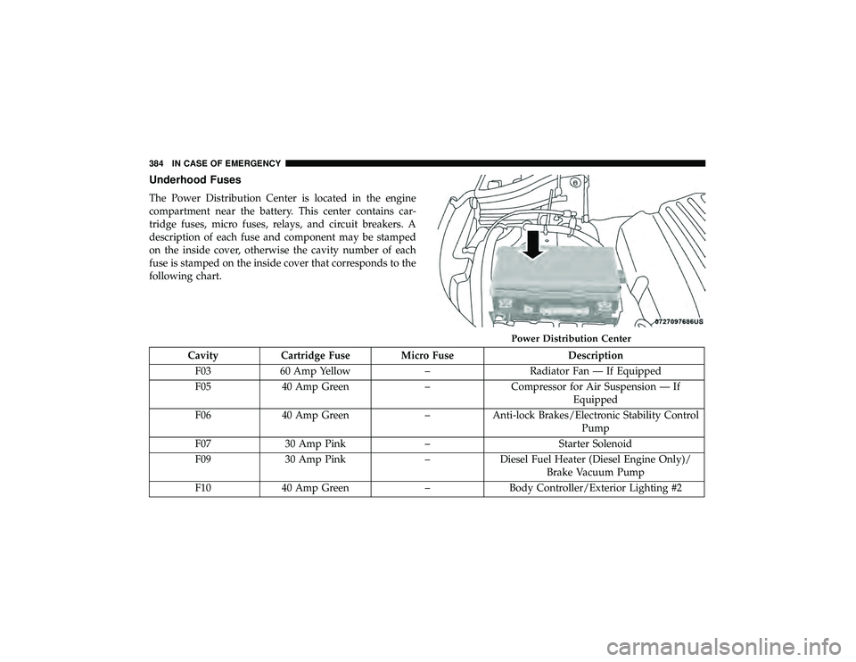
Underhood Fuses
The Power Distribution Center is located in the engine
compartment near the battery. This center contains car-
tridge fuses, micro fuses, relays, and circuit breakers. A
description of each fuse and component may be stamped
on the inside cover, otherwise the cavity number of each
fuse is stamped on the inside cover that corresponds to the
following chart.
CavityCartridge Fuse Micro Fuse Description
F03 60 Amp Yellow –Radiator Fan — If Equipped
F05 40 Amp Green –Compressor for Air Suspension — If
Equipped
F06 40 Amp Green –Anti-lock Brakes/Electronic Stability Control
Pump
F07 30 Amp Pink –Starter Solenoid
F09 30 Amp Pink –Diesel Fuel Heater (Diesel Engine Only)/
Brake Vacuum Pump
F10 40 Amp Green –Body Controller/Exterior Lighting #2
Power Distribution Center
384 IN CASE OF EMERGENCY
Page 387 of 598
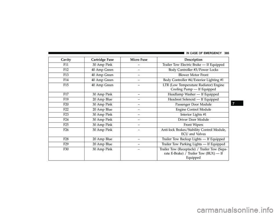
CavityCartridge Fuse Micro Fuse Description
F11 30 Amp Pink –Trailer Tow Electric Brake — If Equipped
F12 40 Amp Green –Body Controller #3/Power Locks
F13 40 Amp Green –Blower Motor Front
F14 40 Amp Green –Body Controller #4/Exterior Lighting #1
F15 40 Amp Green –LTR (Low Temperature Radiator) Engine
Cooling Pump — If Equipped
F17 30 Amp Pink –Headlamp Washer — If Equipped
F19 20 Amp Blue –Headrest Solenoid — If Equipped
F20 30 Amp Pink –Passenger Door Module
F22 20 Amp Blue –Engine Control Module
F23 30 Amp Pink –Interior Lights #1
F24 30 Amp Pink –Driver Door Module
F25 30 Amp Pink – Front Wipers
F26 30 Amp Pink –Anti-lock Brakes/Stability Control Module,
ECU and Valves
F28 20 Amp Blue –Trailer Tow Backup Lights — If Equipped
F29 20 Amp Blue –Trailer Tow Parking Lights — If Equipped
F30 30 Amp Pink –Trailer Tow (Receptacle) / Trailer Tow (Sepa-
rate E-Brake) / Trailer Tow (BUX) — If Equipped
7
IN CASE OF EMERGENCY 385