engine DODGE DURANGO 2020 Repair Manual
[x] Cancel search | Manufacturer: DODGE, Model Year: 2020, Model line: DURANGO, Model: DODGE DURANGO 2020Pages: 464, PDF Size: 22.14 MB
Page 202 of 464
200STARTING AND OPERATING
The LOW RANGE position is designed for loose,
slippery road surfaces only. Driving in the LOW
RANGE position on dry hard surfaced roads may
cause increased tire wear and damage to the
driveline components.
Transfer Case Position Indicator Messages
The Transfer Case Position Indicator messages
(AWD AUTO and LOW RANGE) are located in the
instrument cluster and indicate the current and
desired transfer case selection. Refer to
“Instrument Cluster Display” in “Getting To
Know Your Instrument Panel” for further
information. When you select a different
transfer case position, the position indicator
lights will do the following:
If All Shift Conditions Are Met:
1. The current position indicator light will turn
off.
2. The selected position indicator light will flash until the transfer case completes the
shift.
3. When the shift is complete, the indicator light for the selected position will stop
flashing and remain on. If shift conditions are not met, one or more of
the following events may occur:
1. The indicator light for the current position
will remain on.
2. The newly selected position indicator light will continue to flash.
3. The transfer case will not shift.
NOTE:
Before retrying a selection, make certain that all
the necessary requirements for selecting a new
transfer case position have been met. To retry
the selection, turn the control knob back to the
current position, wait five seconds, and retry
selection. To find the shift requirements, refer
to the "Shifting Procedure" for your transfer
case, located in this section.
The “SERV AWD” Warning Light monitors the
electronic shift all-wheel drive system. If this
light remains on after engine start up or
illuminates during driving, it means that the
all-wheel drive system is not functioning
properly and that service is required. NOTE:
Do not attempt to make a shift while only the
front or rear wheels are spinning. This could
cause damage to driveline components.
When operating your vehicle in LOW RANGE, the
engine speed is approximately three times that
of the AWD AUTO position at a given road speed.
Take care not to overspeed the engine and do
not exceed 25 mph (40 km/h).
Proper operation of all-wheel drive vehicles
depends on tires of equal size, type and
circumference on each wheel. Any difference in
tire size can cause damage to the transfer case.
Because all-wheel drive provides improved
traction, there is a tendency to exceed safe
turning and stopping speeds. Do not go faster
than road conditions permit.
WARNING!
Always engage the parking brake when
powering down the vehicle if the “SERV AWD
Warning Light” is illuminated. Not engaging
the parking brake may allow the vehicle to roll
which may cause personal injury.
20_WD_OM_EN_USC_t.book Page 200
Page 204 of 464
202STARTING AND OPERATING
Preferred Procedure
1. With the engine running, slow the vehicle
to 2 to 3 mph (3 to 5 km/h).
2. Shift the transmission into NEUTRAL.
3. While still rolling, rotate the AWD control switch to the desired position.
4. After the desired position indicator light is on (not flashing), shift the transmission
back into gear.
Alternate Procedure
1. Bring the vehicle to complete stop.
2. With the ignition in ON/RUN position and engine running, shift the transmission to
NEUTRAL.
3. Rotate the AWD control switch to the desired position.
4. After the desired position indicator light is on (not flashing), shift the transmission
back into gear. NOTE:
If steps 1 or 2 of either the Preferred or Alter
-
nate Procedure are not satisfied prior to
attempting the shift or if they no longer are
being met while the shift attempt is in
process, the desired position indicator light
will flash continuously while the original posi -
tion indicator light is on, until all require -
ments have been met.
The ignition switch must be in the ON/RUN
position for a shift to take place and for the
position indicator lights to be operable. If the
ignition switch is not in the ON/RUN position,
then the shift will not take place and no posi -
tion indicator lights will be on or flashing.
NEUTRAL Shift Procedure
For information regarding the transfer case
NEUTRAL (N) shift procedure, refer to “Shifting
Into NEUTRAL (N)” in “Recreational Towing” in
this chapter.
FUEL SAVER TECHNOLOGY 5.7L/6.4L ONLY
— IF EQUIPPED
This feature offers improved fuel economy by
shutting off four of the engine's eight cylinders
during light load and cruise conditions. The
system is automatic with no driver inputs or
additional driving skills required.
NOTE:
This system may take some time to return to full
functionality after a battery disconnect.
POWER STEERING
The electric power steering system will give you
good vehicle response and increased ease of
maneuverability in tight spaces. The system will
vary its assist to provide light efforts while
parking and good feel while driving. If the
electric steering system experiences a fault that
prevents it from providing assist, you will still
have the ability to steer the vehicle manually.
20_WD_OM_EN_USC_t.book Page 202
Page 205 of 464
STARTING AND OPERATING203
Alternate electric power steering efforts can be
selected through the Uconnect System. Refer to
”Customer Programmable Features” within
“Uconnect Settings” in “Multimedia” for further
information.
If the Electric Power Steering warning
icon is displayed and the “SERVICE
POWER STEERING” or the “POWER
STEERING ASSIST OFF – SERVICE
SYSTEM” message is displayed within the
instrument cluster display, this indicates the
vehicle needs to be taken to the dealer for
service. Refer to “Warning Lights And
Messages” in “Getting To Know Your
Instrument Panel” for further information. NOTE:
Even if the power steering assistance is no
longer operational, it is still possible to steer
the vehicle. Under these conditions there will
be a substantial increase in steering effort,
especially at low speeds and during parking
maneuvers.
If the condition persists, see an authorized
dealer for service.
If the Steering icon is displayed and the
“POWER STEERING SYSTEM OVER TEMP”
message is displayed on the instrument cluster
screen, they indicate that extreme steering
maneuvers may have occurred which caused
an over temperature condition in the power
steering system. Once driving conditions are
safe, pull over and let the vehicle idle for a few
moments until the icon and message turn off.
STOP/START SYSTEM — IF EQUIPPED
The Stop/Start function is developed to reduce
fuel consumption. The system will stop the
engine automatically during a vehicle stop if the
required conditions are met. Releasing the
brake pedal or pressing the accelerator pedal
will automatically re-start the engine. This vehicle has been upgraded with a heavy
duty starter, enhanced battery, and other
upgraded engine parts, to handle the additional
engine starts.
AUTOMATIC MODE
The Stop/Start feature is enabled
after every normal customer engine
start. At that time, the system will go
into STOP/START READY and if all
other conditions are met, can go into a STOP/
START AUTOSTOP ACTIVE “Autostop” mode.
To Activate The Autostop Mode, The Following
Must Occur:
The system must be in STOP/START READY
state. A STOP/START READY message will be
displayed in the instrument cluster display
within the Stop/Start section. Refer to
“Instrument Cluster” in “Getting To Know
Your Instrument Panel” for further informa -
tion.
The vehicle must be completely stopped.
The gear selector must be in a forward gear
and the brake pedal depressed.
WARNING!
Continued operation with reduced assist
could pose a safety risk to yourself and
others. Service should be obtained as soon
as possible.
5
20_WD_OM_EN_USC_t.book Page 203
Page 206 of 464
204STARTING AND OPERATING
The engine will shut down, the tachometer will
move to the zero position and the Stop/Start
telltale will illuminate indicating you are in
Autostop. Customer settings will be maintained
upon return to an engine running condition.
Refer to the “Stop/Start System” in the
“Starting And Operating” section for further
information.
POSSIBLE REASONS THE ENGINE DOES
N
OT AUTOSTOP
Prior to engine shut down, the system will check
many safety and comfort conditions to see if
they are fulfilled. Detailed information about the
operation of the Stop/Start system may be
viewed in the instrument cluster display Stop/
Start Screen. In the following situations, the
engine will not stop:
Driver’s seat belt is not buckled.
Driver’s door is not closed.
Battery temperature is too warm or cold.
Battery charge is low.
The vehicle is on a steep grade.
Cabin heating or cooling is in process and an
acceptable cabin temperature has not been
achieved.
HVAC is set to full defrost mode at a high
blower speed.
HVAC set to MAX A/C.
Engine has not reached normal operating
temperature.
The transmission is not in a forward gear.
Hood is open.
Brake pedal is not pressed with sufficient
pressure.
Other Factors Which Can Inhibit Autostop
Include:
Accelerator pedal input.
Engine temp too high.
5 mph (8 km/h) threshold not achieved from
previous Autostop.
Steering angle beyond threshold.
ACC is on and speed is set. It may be possible for the vehicle to be driven
several times without the Stop/Start system
going into a STOP/START READY state under
more extreme conditions of the items listed
above.
TO START THE ENGINE WHILE IN
A
UTOSTOP MODE
While in a forward gear, the engine will start
when the brake pedal is released or the throttle
pedal is depressed. The transmission will
automatically re-engage upon engine restart.
Conditions That Will Cause The Engine To Start
Automatically While In Autostop Mode:
The transmission selector is moved out of
DRIVE.
To maintain cabin temperature comfort.
HVAC is set to full defrost mode.
HVAC system temperature or fan speed is
manually adjusted.
Battery voltage drops too low.
20_WD_OM_EN_USC_t.book Page 204
Page 207 of 464
STARTING AND OPERATING205
Low brake vacuum (e.g. after several brake
pedal applications).
Stop/Start OFF switch is pushed.
A Stop/Start system error occurs.
TO MANUALLY TURN OFF THE STOP/
S
TART SYSTEM
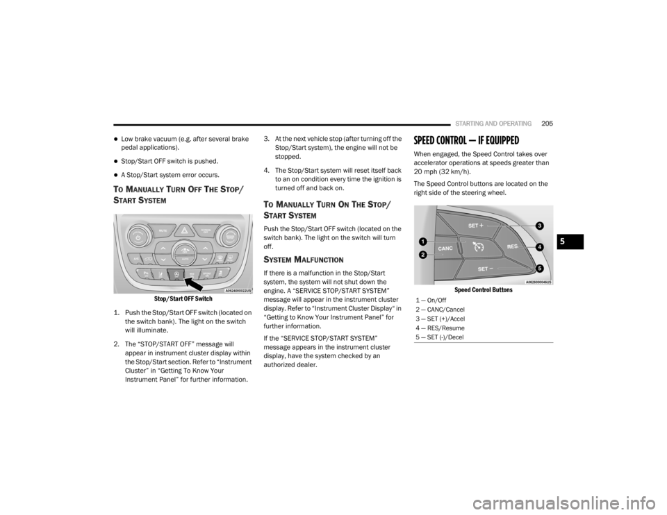
Stop/Start OFF Switch
1. Push the Stop/Start OFF switch (located on the switch bank). The light on the switch
will illuminate.
2. The “STOP/START OFF” message will appear in instrument cluster display within
the Stop/Start section. Refer to “Instrument
Cluster” in “Getting To Know Your
Instrument Panel” for further information. 3. At the next vehicle stop (after turning off the
Stop/Start system), the engine will not be
stopped.
4. The Stop/Start system will reset itself back to an on condition every time the ignition is
turned off and back on.
TO MANUALLY TURN ON THE STOP/
S
TART SYSTEM
Push the Stop/Start OFF switch (located on the
switch bank). The light on the switch will turn
off.
SYSTEM MALFUNCTION
If there is a malfunction in the Stop/Start
system, the system will not shut down the
engine. A “SERVICE STOP/START SYSTEM”
message will appear in the instrument cluster
display. Refer to “Instrument Cluster Display“ in
“Getting to Know Your Instrument Panel” for
further information.
If the “SERVICE STOP/START SYSTEM”
message appears in the instrument cluster
display, have the system checked by an
authorized dealer.
SPEED CONTROL — IF EQUIPPED
When engaged, the Speed Control takes over
accelerator operations at speeds greater than
20 mph (32 km/h).
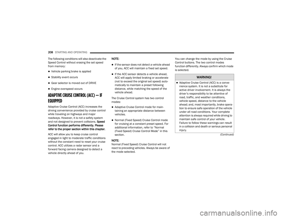
The Speed Control buttons are located on the
right side of the steering wheel.
Speed Control Buttons
1 — On/Off
2 — CANC/Cancel
3 — SET (+)/Accel
4 — RES/Resume
5 — SET (-)/Decel
5
20_WD_OM_EN_USC_t.book Page 205
Page 210 of 464
208STARTING AND OPERATING
(Continued)
The following conditions will also deactivate the
Speed Control without erasing the set speed
from memory:
Vehicle parking brake is applied
Stability event occurs
Gear selector is moved out of DRIVE
Engine overspeed occurs
ADAPTIVE CRUISE CONTROL (ACC) — IF
EQUIPPED
Adaptive Cruise Control (ACC) increases the
driving convenience provided by cruise control
while traveling on highways and major
roadways. However, it is not a safety system
and not designed to prevent collisions. Speed
Control function performs differently. Please
refer to the proper section within this chapter.
ACC will allow you to keep cruise control
engaged in light to moderate traffic conditions
without the constant need to reset your cruise
control. ACC utilizes a radar sensor and a
forward facing camera designed to detect a
vehicle directly ahead of you. NOTE:
If the sensor does not detect a vehicle ahead
of you, ACC will maintain a fixed set speed.
If the ACC sensor detects a vehicle ahead,
ACC will apply limited braking or accelerate
(not to exceed the original set speed) auto
-
matically to maintain a preset following
distance, while matching the speed of the
vehicle ahead.
The Cruise Control system has two control
modes:
Adaptive Cruise Control mode for main -
taining an appropriate distance between
vehicles.
Normal (Fixed Speed) Cruise Control mode
for cruising at a constant preset speed. For
additional information, refer to “Normal
(Fixed Speed) Cruise Control Mode” in this
section.
NOTE:
Normal (Fixed Speed) Cruise Control will not
react to preceding vehicles. Always be aware of
the mode selected. You can change the mode by using the Cruise
Control buttons. The two control modes
function differently. Always confirm which mode
is selected.
WARNING!
Adaptive Cruise Control (ACC) is a conve
-
nience system. It is not a substitute for
active driver involvement. It is always the
driver’s responsibility to be attentive of
road, traffic, and weather conditions,
vehicle speed, distance to the vehicle
ahead; and, most importantly, brake opera -
tion to ensure safe operation of the vehicle
under all road conditions. Your complete
attention is always required while driving to
maintain safe control of your vehicle.
Failure to follow these warnings can result
in a collision and death or serious personal
injury.
20_WD_OM_EN_USC_t.book Page 208
Page 214 of 464
212STARTING AND OPERATING
TO VARY THE SPEED SETTING
To Increase Speed
While ACC is set, you can increase the set speed
by pushing the SET (+) button.
The driver's preferred units can be selected
through the instrument panel settings. Refer to
“Getting To Know Your Instrument Panel” for
more information. The speed increment shown
is dependent on the chosen speed unit of U.S.
(mph) or Metric (km/h):
U.S. Speed (mph)
Pushing the SET (+) button once will result in
a 1 mph increase in set speed. Each subse -
quent tap of the button results in an increase
of 1 mph.
If the button is continually pushed, the set
speed will continue to increase in 5 mph
increments until the button is released. The
increase in set speed is reflected in the
instrument cluster display. Metric Speed (km/h)
Pushing the SET (+) button once will result in
a 1 km/h increase in set speed. Each subse -
quent tap of the button results in an increase
of 1 km/h.
If the button is continually pushed, the set
speed will continue to increase in 10 km/h
increments until the button is released. The
increase in set speed is reflected in the
instrument cluster display.
To Decrease Speed
While ACC is set, the set speed can be
decreased by pushing the SET (-) button.
The driver's preferred units can be selected
through the instrument panel settings. Refer to
“Getting To Know Your Instrument Panel” for
more information. The speed decrement shown
is dependent on the chosen speed unit of U.S.
(mph) or Metric (km/h):
U.S. Speed (mph)
Pushing the SET (-) button once will result in
a 1 mph decrease in set speed. Each subse -
quent tap of the button results in a decrease
of 1 mph.
If the button is continually pushed, the set
speed will continue to decrease in 5 mph
decrements until the button is released. The
decrease in set speed is reflected in the
instrument cluster display.
Metric Speed (km/h)
Pushing the SET (-) button once will result in
a 1 km/h decrease in set speed. Each subse -
quent tap of the button results in a decrease
of 1 km/h.
If the button is continually pushed, the set
speed will continue to decrease in 10 km/h
decrements until the button is released. The
decrease in set speed is reflected in the
instrument cluster display.
NOTE:
When you override and push the SET (+)
button or SET (-) buttons, the new set speed
will be the current speed of the vehicle.
When you use the SET (-) button to decel -
erate, if the engine’s braking power does not
slow the vehicle sufficiently to reach the set
speed, the brake system will automatically
slow the vehicle.
20_WD_OM_EN_USC_t.book Page 212
Page 241 of 464
STARTING AND OPERATING239
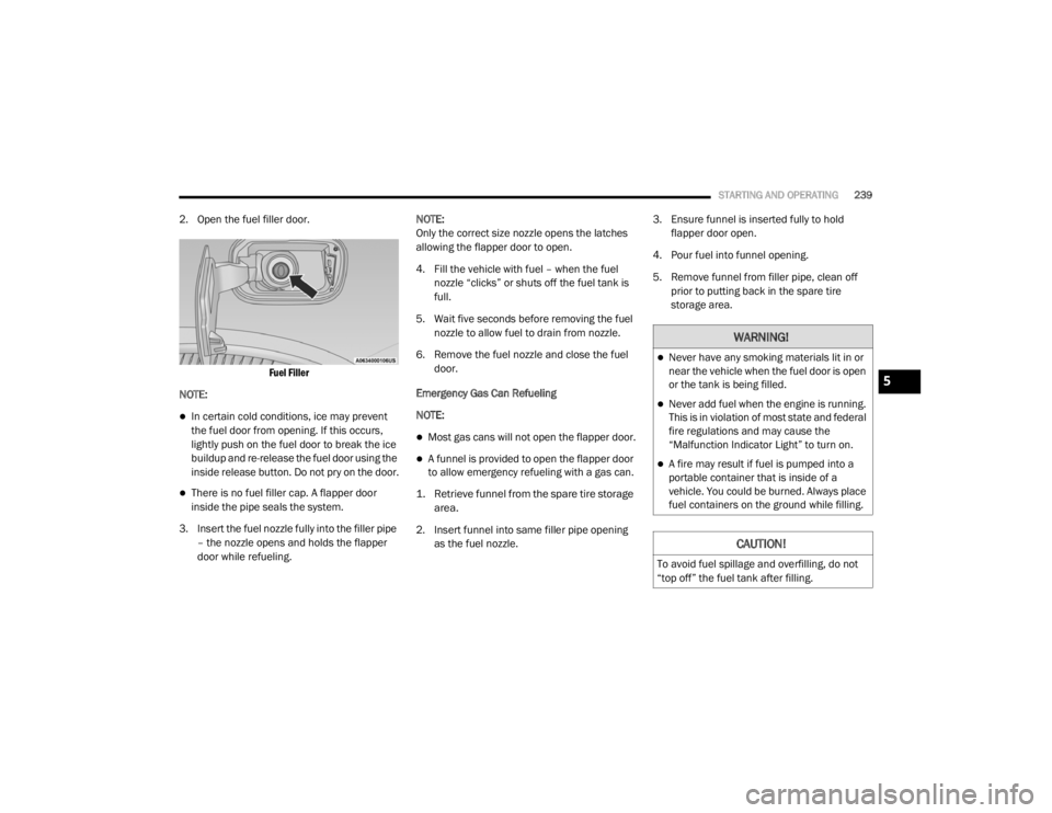
2. Open the fuel filler door.
Fuel Filler
NOTE:
In certain cold conditions, ice may prevent
the fuel door from opening. If this occurs,
lightly push on the fuel door to break the ice
buildup and re-release the fuel door using the
inside release button. Do not pry on the door.
There is no fuel filler cap. A flapper door
inside the pipe seals the system.
3. Insert the fuel nozzle fully into the filler pipe – the nozzle opens and holds the flapper
door while refueling. NOTE:
Only the correct size nozzle opens the latches
allowing the flapper door to open.
4. Fill the vehicle with fuel – when the fuel
nozzle “clicks” or shuts off the fuel tank is
full.
5. Wait five seconds before removing the fuel nozzle to allow fuel to drain from nozzle.
6. Remove the fuel nozzle and close the fuel door.
Emergency Gas Can Refueling
NOTE:
Most gas cans will not open the flapper door.
A funnel is provided to open the flapper door
to allow emergency refueling with a gas can.
1. Retrieve funnel from the spare tire storage area.
2. Insert funnel into same filler pipe opening as the fuel nozzle. 3. Ensure funnel is inserted fully to hold
flapper door open.
4. Pour fuel into funnel opening.
5. Remove funnel from filler pipe, clean off prior to putting back in the spare tire
storage area.
WARNING!
Never have any smoking materials lit in or
near the vehicle when the fuel door is open
or the tank is being filled.
Never add fuel when the engine is running.
This is in violation of most state and federal
fire regulations and may cause the
“Malfunction Indicator Light” to turn on.
A fire may result if fuel is pumped into a
portable container that is inside of a
vehicle. You could be burned. Always place
fuel containers on the ground while filling.
CAUTION!
To avoid fuel spillage and overfilling, do not
“top off” the fuel tank after filling.
5
20_WD_OM_EN_USC_t.book Page 239
Page 244 of 464

242STARTING AND OPERATING
Gross Trailer Weight (GTW)
The GTW is the weight of the trailer plus the
weight of all cargo, consumables and
equipment (permanent or temporary) loaded in
or on the trailer in its "loaded and ready for
operation" condition.
The recommended way to measure GTW is to
put your fully loaded trailer on a vehicle scale.
The entire weight of the trailer must be
supported by the scale.
Gross Combination Weight Rating (GCWR)
The GCWR is the total allowable weight of your
vehicle and trailer when weighed in
combination.
Gross Axle Weight Rating (GAWR)
The GAWR is the maximum capacity of the front
and rear axles. Distribute the load over the front
and rear axles evenly. Make sure that you do
not exceed either front or rear GAWR. Refer to
“Vehicle Loading/Vehicle Certification Label” in
this chapter for further information.
Tongue Weight (TW)
The tongue weight is the downward force
exerted on the hitch ball by the trailer. You must
consider this as part of the load on your vehicle.
Trailer Frontal Area
The frontal area is the maximum height
multiplied by the maximum width of the front of
a trailer.
Trailer Sway Control
The trailer sway control can be a mechanical
telescoping link that can be installed between
the hitch receiver and the trailer tongue that
typically provides adjustable friction associated
with the telescoping motion to dampen any
unwanted trailer swaying motions while
traveling.
If equipped, the electronic Trailer Sway Control
(TSC) recognizes a swaying trailer and
automatically applies individual wheel brakes
and/or reduces engine power to attempt to
eliminate the trailer sway.WARNING!
If the gross trailer weight is 5,000 lbs
(2,267 kg) or more, it is recommended to use
a weight-distributing hitch to ensure stable
handling of your vehicle. If you use a standard
weight-carrying hitch, you could lose control
of your vehicle and cause a collision.WARNING!
It is important that you do not exceed the
maximum front or rear GAWR. A dangerous
driving condition can result if either rating is
exceeded. You could lose control of the
vehicle and have a collision.
20_WD_OM_EN_USC_t.book Page 242
Page 246 of 464
244STARTING AND OPERATING
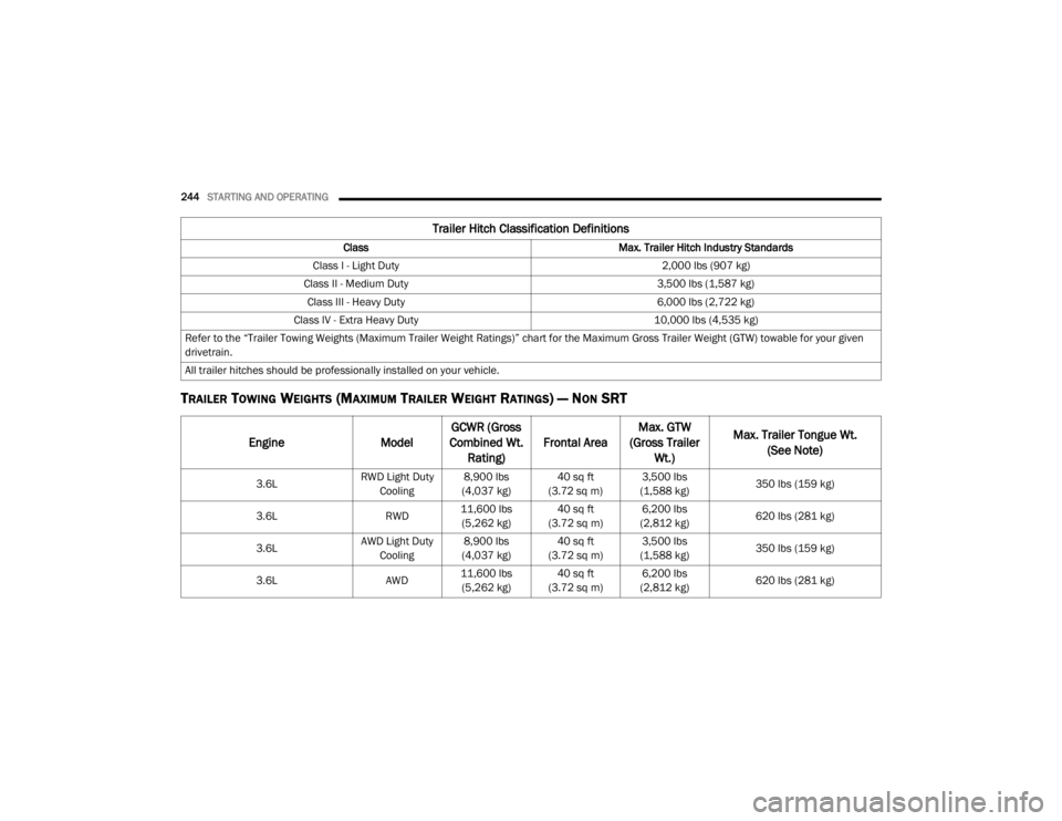
TRAILER TOWING WEIGHTS (MAXIMUM TRAILER WEIGHT RATINGS) — NON SRT
Trailer Hitch Classification Definitions
Class Max. Trailer Hitch Industry Standards
Class I - Light Duty 2,000 lbs (907 kg)
Class II - Medium Duty 3,500 lbs (1,587 kg)
Class III - Heavy Duty 6,000 lbs (2,722 kg)
Class IV - Extra Heavy Duty 10,000 lbs (4,535 kg)
Refer to the “Trailer Towing Weights (Maximum Trailer Weight Ratings)” chart for the Maximum Gross Trailer Weight (GTW) towable for your given
drivetrain.
All trailer hitches should be professionally installed on your vehicle.
Engine ModelGCWR (Gross
Combined Wt. Rating) Frontal Area Max. GTW
(Gross Trailer Wt.) Max. Trailer Tongue Wt.
(See Note)
3.6L RWD Light Duty
Cooling 8,900 lbs
(4,037 kg) 40 sq ft
(3.72 sq m) 3,500 lbs
(1,588 kg) 350 lbs (159 kg)
3.6L RWD11,600 lbs
(5,262 kg) 40 sq ft
(3.72 sq m) 6,200 lbs
(2,812 kg) 620 lbs (281 kg)
3.6L AWD Light Duty
Cooling 8,900 lbs
(4,037 kg) 40 sq ft
(3.72 sq m) 3,500 lbs
(1,588 kg) 350 lbs (159 kg)
3.6L AWD11,600 lbs
(5,262 kg) 40 sq ft
(3.72 sq m) 6,200 lbs
(2,812 kg) 620 lbs (281 kg)
20_WD_OM_EN_USC_t.book Page 244