brake sensor DODGE DURANGO 2020 Owners Manual
[x] Cancel search | Manufacturer: DODGE, Model Year: 2020, Model line: DURANGO, Model: DODGE DURANGO 2020Pages: 464, PDF Size: 22.14 MB
Page 127 of 464
SAFETY125
(Continued)
Electronic Stability Control (ESC)
This system enhances directional control and
stability of the vehicle under various driving
conditions. Electronic Stability Control (ESC)
corrects for oversteering or understeering of the
vehicle by applying the brake of the appropriate
wheel(s) to assist in counteracting the oversteer
or understeer condition. Engine power may also
be reduced to help the vehicle maintain the
desired path. ESC uses sensors in the vehicle to determine
the vehicle path intended by the driver and
compares it to the actual path of the vehicle.
When the actual path does not match the
intended path, ESC applies the brake of the
appropriate wheel to assist in counteracting the
oversteer or understeer condition.
Oversteer — when the vehicle is turning more
than appropriate for the steering wheel posi
-
tion.
Understeer — when the vehicle is turning less
than appropriate for the steering wheel posi -
tion.
The “ESC Activation/Malfunction Indicator
Light” located in the instrument cluster will start
to flash as soon as the ESC system becomes
active. The “ESC Activation/Malfunction
Indicator Light” also flashes when the Traction
Control System (TCS) is active. If the “ESC
Activation/Malfunction Indicator Light” begins
to flash during acceleration, ease up on the
accelerator and apply as little throttle as
possible. Be sure to adapt your speed and
driving to the prevailing road conditions.
WARNING!
Many factors, such as vehicle loading, road
conditions and driving conditions, influence
the chance that wheel lift or rollover may
occur. ERM cannot prevent all wheel lift or roll
overs, especially those that involve leaving
the roadway or striking objects or other
vehicles. The capabilities of an
ERM-equipped vehicle must never be
exploited in a reckless or dangerous manner
which could jeopardize the user's safety or
the safety of others.
WARNING!
Electronic Stability Control (ESC) cannot
prevent the natural laws of physics from
acting on the vehicle, nor can it increase
the traction afforded by prevailing road
conditions. ESC cannot prevent accidents,
including those resulting from excessive
speed in turns, driving on very slippery
surfaces, or hydroplaning. ESC also cannot
prevent accidents resulting from loss of
vehicle control due to inappropriate driver
input for the conditions. Only a safe, atten -
tive, and skillful driver can prevent acci -
dents. The capabilities of an ESC equipped
vehicle must never be exploited in a reck -
less or dangerous manner which could
jeopardize the user’s safety or the safety of
others.
4
20_WD_OM_EN_USC_t.book Page 125
Page 132 of 464
130SAFETY
Traction Control System (TCS)
The Traction Control System (TCS) monitors the
amount of wheel spin of each of the driven
wheels. If wheel spin is detected, the TCS may
apply brake pressure to the spinning wheel(s)
and/or reduce engine power to provide
enhanced acceleration and stability. A feature
of the TCS, Brake Limited Differential (BLD),
functions similar to a limited slip differential
and controls the wheel spin across a driven
axle. If one wheel on a driven axle is spinning
faster than the other, the system will apply the
brake of the spinning wheel. This will allow more
engine power to be applied to the wheel that is
not spinning. BLD may remain enabled even if
TCS and ESC are in reduced modes.
Rain Brake Support (RBS)
Rain Brake Support (RBS) may improve braking
performance in wet conditions. It will
periodically apply a small amount of brake
pressure to remove any water buildup on the
front brake rotors. It functions when the
windshield wipers are in LO or HI speed. When Rain Brake Support is active, there is no
notification to the driver and no driver
interaction is required.
Ready Alert Braking (RAB)
Ready Alert Braking (RAB) may reduce the time
required to reach full braking during emergency
braking situations. It anticipates when an
emergency braking situation may occur by
monitoring how fast the throttle is released by
the driver. The EBC will prepare the brake
system for a panic stop.
Trailer Sway Control (TSC)
Trailer Sway Control (TSC) uses sensors in the
vehicle to recognize an excessively swaying
trailer and will take the appropriate actions to
attempt to stop the sway. TSC will become
active automatically once an excessively
swaying trailer is recognized. Note that TSC
cannot stop all trailers from swaying. Always
use caution when towing a trailer and follow the
trailer tongue weight recommendations.
Refer to “Trailer Towing” in “Starting And
Operating” for more information. When TSC is
functioning, the “ESC Activation/Malfunction
Indicator Light” will flash, the engine power may
be reduced and you may feel the brakes being
applied to individual wheels to attempt to stop
the trailer from swaying. TSC is disabled when
the ESC system is in the “Partial Off” mode.
WARNING!
If TSC activates while driving, slow the vehicle
down, stop at the nearest safe location, and
adjust the trailer load to eliminate trailer
sway.
20_WD_OM_EN_USC_t.book Page 130
Page 138 of 464
136SAFETY
FORWARD COLLISION WARNING (FCW)
W
ITH MITIGATION
The Forward Collision Warning (FCW) with
Mitigation system provides the driver with
audible warnings, visual warnings (within the
instrument cluster display), and may apply a
brake jerk to warn the driver when it detects a
potential frontal collision. The warnings and
limited braking are intended to provide the
driver with enough time to react, avoid or
mitigate the potential collision.
NOTE:
FCW monitors the information from the forward
looking sensors as well as the Electronic Brake
Controller (EBC), to calculate the probability of a
forward collision. When the system determines
that a forward collision is probable, the driver
will be provided with audible and visual warn-
ings and may provide a brake jerk warning. If
the driver does not take action based upon
these progressive warnings, then the system
will provide a limited level of active braking to
help slow the vehicle and mitigate the potential
forward collision. If the driver reacts to the warnings by braking
and the system determines that the driver
intends to avoid the collision by braking but has
not applied sufficient brake force, the system
will compensate and provide additional brake
force as required.
If a Forward Collision Warning with Mitigation
event begins at a speed below 26 mph
(42 km/h), the system may provide the
maximum or partial braking to mitigate the
potential forward collision. If the Forward
Collision Warning with Mitigation event stops
the vehicle completely, the system will hold the
vehicle at a standstill for two seconds and then
release the brakes.
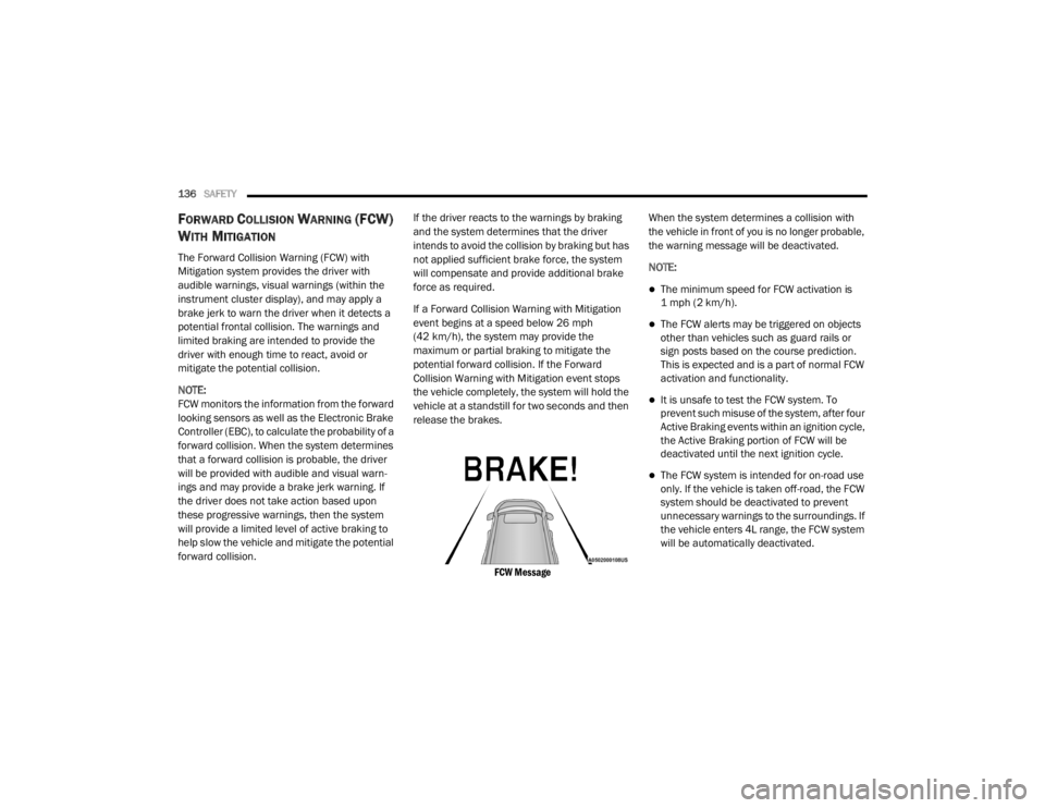
FCW Message
When the system determines a collision with
the vehicle in front of you is no longer probable,
the warning message will be deactivated.
NOTE:
The minimum speed for FCW activation is
1 mph (2 km/h).
The FCW alerts may be triggered on objects
other than vehicles such as guard rails or
sign posts based on the course prediction.
This is expected and is a part of normal FCW
activation and functionality.
It is unsafe to test the FCW system. To
prevent such misuse of the system, after four
Active Braking events within an ignition cycle,
the Active Braking portion of FCW will be
deactivated until the next ignition cycle.
The FCW system is intended for on-road use
only. If the vehicle is taken off-road, the FCW
system should be deactivated to prevent
unnecessary warnings to the surroundings. If
the vehicle enters 4L range, the FCW system
will be automatically deactivated.
20_WD_OM_EN_USC_t.book Page 136
Page 210 of 464
208STARTING AND OPERATING
(Continued)
The following conditions will also deactivate the
Speed Control without erasing the set speed
from memory:
Vehicle parking brake is applied
Stability event occurs
Gear selector is moved out of DRIVE
Engine overspeed occurs
ADAPTIVE CRUISE CONTROL (ACC) — IF
EQUIPPED
Adaptive Cruise Control (ACC) increases the
driving convenience provided by cruise control
while traveling on highways and major
roadways. However, it is not a safety system
and not designed to prevent collisions. Speed
Control function performs differently. Please
refer to the proper section within this chapter.
ACC will allow you to keep cruise control
engaged in light to moderate traffic conditions
without the constant need to reset your cruise
control. ACC utilizes a radar sensor and a
forward facing camera designed to detect a
vehicle directly ahead of you. NOTE:
If the sensor does not detect a vehicle ahead
of you, ACC will maintain a fixed set speed.
If the ACC sensor detects a vehicle ahead,
ACC will apply limited braking or accelerate
(not to exceed the original set speed) auto
-
matically to maintain a preset following
distance, while matching the speed of the
vehicle ahead.
The Cruise Control system has two control
modes:
Adaptive Cruise Control mode for main -
taining an appropriate distance between
vehicles.
Normal (Fixed Speed) Cruise Control mode
for cruising at a constant preset speed. For
additional information, refer to “Normal
(Fixed Speed) Cruise Control Mode” in this
section.
NOTE:
Normal (Fixed Speed) Cruise Control will not
react to preceding vehicles. Always be aware of
the mode selected. You can change the mode by using the Cruise
Control buttons. The two control modes
function differently. Always confirm which mode
is selected.
WARNING!
Adaptive Cruise Control (ACC) is a conve
-
nience system. It is not a substitute for
active driver involvement. It is always the
driver’s responsibility to be attentive of
road, traffic, and weather conditions,
vehicle speed, distance to the vehicle
ahead; and, most importantly, brake opera -
tion to ensure safe operation of the vehicle
under all road conditions. Your complete
attention is always required while driving to
maintain safe control of your vehicle.
Failure to follow these warnings can result
in a collision and death or serious personal
injury.
20_WD_OM_EN_USC_t.book Page 208
Page 215 of 464
STARTING AND OPERATING213
The ACC system applies the brake down to a
full stop when following a target vehicle. If an
ACC host vehicle follows a target vehicle to a
standstill, the host vehicle will release the
vehicle brakes two seconds after coming to a
full stop.
The ACC system maintains set speed when
driving uphill and downhill. However, a slight
speed change on moderate hills is normal. In
addition, downshifting may occur while
climbing uphill or descending downhill. This
is normal operation and necessary to main -
tain set speed. When driving uphill and down -
hill, the ACC system will cancel if the braking
temperature exceeds normal range (over -
heated).
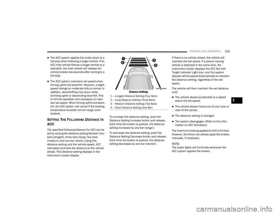
SETTING THE FOLLOWING DISTANCE IN
ACC
The specified following distance for ACC can be
set by varying the distance setting between four
bars (longest), three bars (long), two bars
(medium) and one bar (short). Using this
distance setting and the vehicle speed, ACC
calculates and sets the distance to the vehicle
ahead. This distance setting displays in the
instrument cluster display.
Distance Settings
To increase the distance setting, push the
Distance Setting Increase button and release.
Each time the button is pushed, the distance
setting increases by one bar (longer).
To decrease the distance setting, push the
Distance Setting Decrease button and release.
Each time the button is pushed, the distance
setting decreases by one bar (shorter). If there is no vehicle ahead, the vehicle will
maintain the set speed. If a slower moving
vehicle is detected in the same lane, the
instrument cluster displays the ACC Set with
Target Indicator Light icon, and the system
adjusts vehicle speed automatically to maintain
the distance setting, regardless of the set
speed.
The vehicle will then maintain the set distance
until:
The vehicle ahead accelerates to a speed
above the set speed.
The vehicle ahead moves out of your lane or
view of the sensor.
The distance setting is changed.
The system disengages. (Refer to the infor
-
mation on ACC Activation).
The maximum braking applied by ACC is limited;
however, the driver can always apply the brakes
manually, if necessary.
NOTE:
The brake lights will illuminate whenever the
ACC system applies the brakes.
1 — Longest Distance Setting (Four Bars)
2 — Long Distance Setting (Three Bars)
3 — Medium Distance Setting (Two Bars)
4 — Short Distance Setting (One Bar)
5
20_WD_OM_EN_USC_t.book Page 213
Page 227 of 464
STARTING AND OPERATING225
ENABLING AND DISABLING PARKSENSE
ParkSense can be enabled and disabled with
the ParkSense switch.
When the ParkSense switch is pushed
to disable the system, the instrument
cluster will display the “PARKSENSE
OFF” message for approximately five
seconds. When the gear selector is moved to
REVERSE and the system is disabled, the
instrument cluster display will display the
“PARKSENSE OFF” message for as long as the
vehicle is in REVERSE.
Refer to “Instrument Cluster Display” in
“Getting To Know Your Instrument Panel” for
further information.
The ParkSense switch LED will be on when
ParkSense is disabled or requires service. The
ParkSense switch LED will be off when the
system is enabled. If the ParkSense switch is
pushed, and the system requires service, the
ParkSense switch LED will blink momentarily,
and then the LED will be on.
OPERATION WITH A TRAILER
For vehicles equipped with an Integrated Trailer
Brake Module (ITBM), the operation of the rear
sensors is automatically deactivated when the
trailer's electric plug is inserted in the vehicle's
tow hook socket. When the vehicle is connected
to a trailer, the instrument cluster display will
show the “Rear ParkSense Unavailable Trailer
Connected” message in the following
situations:
For five seconds at vehicle start up
For five seconds when the ParkSense button
is pushed
As long as the vehicle is in REVERSE
NOTE:
Refer to “Towing Requirements” in “Starting
And Operating” for more information on the
Integrated Trailer Brake Module.
SERVICE THE PARKSENSE REAR PARK
A
SSIST SYSTEM
During vehicle start up, when the ParkSense
Rear Park Assist system has detected a faulted
condition, the instrument cluster will actuate a
single chime, once per ignition cycle, and it will display the “PARKSENSE UNAVAILABLE WIPE
REAR SENSORS” or the “PARKSENSE
UNAVAILABLE SERVICE REQUIRED” message.
Refer to “Instrument Cluster Display” in
“Getting To Know Your Instrument Panel” for
further information. When the gear selector is
moved to REVERSE and the system has
detected a faulted condition, the instrument
cluster display will display the "PARKSENSE
UNAVAILABLE WIPE REAR SENSORS" or
"PARKSENSE UNAVAILABLE SERVICE
REQUIRED" message for as long as the vehicle
is in REVERSE. Under this condition, ParkSense
will not operate.
If “PARKSENSE UNAVAILABLE WIPE REAR
SENSORS” appears in the instrument cluster
display make sure the outer surface and the
underside of the rear fascia/bumper is clean
and clear of snow, ice, mud, dirt or other
obstruction and then cycle the ignition. If the
message continues to appear, see an
authorized dealer.
If “PARKSENSE UNAVAILABLE SERVICE
REQUIRED” appears in the instrument cluster
display, see an authorized dealer.
5
20_WD_OM_EN_USC_t.book Page 225
Page 229 of 464
STARTING AND OPERATING227
PARKSENSE FRONT AND REAR PARK ASSIST
— IF EQUIPPED
The ParkSense Park Assist system provides
visual and audible indications of the distance
between the rear and/or front fascia and a
detected obstacle when backing up or moving
forward (e.g. during a parking maneuver). If your vehicle is equipped with an automatic
transmission, the vehicle brakes may be
automatically applied and released when
performing a reverse parking maneuver if the
system detects a possible collision with an
obstacle.
NOTE:
The driver can disable the automatic braking
function by turning ParkSense off via the
ParkSense switch. The driver can also over
-
ride automatic braking by changing the gear
or by pressing the gas pedal over 90% of its
capacity during the braking event.
Automatic brakes are not available if the
vehicle is in 4WD Low.
Automatic brakes will not be available if there
is a faulted condition detected with the Park -
Sense Park Assist system or the Braking
System Module.
The automatic braking function may only be
applied if the vehicle deceleration is not
enough to avoid colliding with a detected
obstacle.
The automatic braking function may not be
applied fast enough for obstacles that move
toward the rear of the vehicle from the left
and/or right sides.
The automatic braking function can be
enabled/disabled from the Customer
Programmable Features section of the Ucon -
nect System.
ParkSense will retain its last known configu -
ration state for the automatic braking func -
tion through ignition cycles.
The automatic braking function is intended to
assist the driver in avoiding possible collisions
with detected obstacles when backing up in
REVERSE gear.
NOTE:
The driver is always responsible for
controlling the vehicle.
The system is designed to assist the driver
and not to substitute the driver.
The driver must stay in full control of the
vehicle's acceleration and braking and is
responsible for the vehicle's movements.
CAUTION!
ParkSense is only a parking aid and it is
unable to recognize every obstacle,
including small obstacles. Parking curbs
might be temporarily detected or not
detected at all. Obstacles located above or
below the sensors will not be detected
when they are in close proximity.
The vehicle must be driven slowly when
using ParkSense in order to be able to stop
in time when an obstacle is detected. It is
recommended that the driver looks over
his/her shoulder when using ParkSense.
5
20_WD_OM_EN_USC_t.book Page 227
Page 233 of 464
STARTING AND OPERATING231
NOTE:
ParkSense will reduce the volume of the radio,
if on, when the system is sounding an audio
tone.
Front Park Assist Audible Alerts
ParkSense will turn off the Front Park Assist
audible alert (chime) after approximately three
seconds when an obstacle has been detected,
the vehicle is stationary, and brake pedal is
applied.
Adjustable Chime Volume Settings
Front and Rear chime volume settings can be
selected from the Uconnect System. Refer to
"Uconnect Settings” in “Multimedia” for further
information.
The chime volume settings include low,
medium, and high. The factory default volume
setting is medium.
ParkSense will retain its last known
configuration state through ignition cycles.
PARKSENSE WARNING DISPLAY
The ParkSense Warning screen will only be
displayed if Sound and Display is selected from
the Customer Programmable Features section
of the Uconnect System. Refer to "Uconnect Settings” in “Multimedia” for
further information.
The ParkSense Warning screen is located within
the instrument cluster display. It provides visual
warnings to indicate the distance between the
rear fascia/bumper and/or front fascia/bumper
and the detected obstacle. Refer to “Instrument
Cluster Display” in “Getting To Know Your
Instrument Panel” for further information.
ENABLING AND DISABLING PARKSENSE
ParkSense can be enabled and disabled with
the ParkSense switch.
When the ParkSense switch is pushed
to disable the system, the instrument
cluster will display the “PARKSENSE
OFF” message for approximately five
seconds. When the gear selector is moved to
REVERSE and the system is disabled, the
instrument cluster display will display the
“PARKSENSE OFF” message for as long as the
vehicle is in REVERSE.
Refer to “Instrument Cluster Display” in
“Getting To Know Your Instrument Panel” for
further information. NOTE:
When ParkSense is disabled and the gear
selector is moved to the DRIVE position, no
warning message will be displayed.
The ParkSense switch LED will be on when
ParkSense is disabled or requires service. The
ParkSense switch LED will be off when the
system is enabled. If the ParkSense switch is
pushed, and the system requires service, the
ParkSense switch LED will blink momentarily,
and then the LED will be on.OPERATION WITH A TRAILER
For vehicles equipped with an Integrated Trailer
Brake Module (ITBM), the operation of the rear
sensors is automatically deactivated when the
trailer's electric plug is inserted in the vehicle's
tow hook socket. The front system is still
functional, and the arcs will be overlaid with a
“Trailer” message. The rear sensors are
automatically reactivated when the trailer's
cable plug is removed.
5
20_WD_OM_EN_USC_t.book Page 231
Page 234 of 464

232STARTING AND OPERATING
When the vehicle is connected to a trailer, the
instrument cluster display will show the "Rear
ParkSense Unavailable Trailer Connected"
message in the following situations:
For five seconds at vehicle start up
For five seconds when the ParkSense button
is pushed, as long as an object is not
detected in the front
As long as the vehicle is in REVERSE (vehicle
graphic displayed with a trailer overlay)
NOTE:
Refer to “Towing Requirements” in “Starting
And Operating” for more information on the
Integrated Trailer Brake Module.
SERVICE THE PARKSENSE PARK ASSIST
S
YSTEM
During vehicle start up, when the ParkSense
System has detected a faulted condition, the
instrument cluster will actuate a single chime,
once per ignition cycle, and it will display the
"PARKSENSE UNAVAILABLE WIPE REAR
SENSORS", "PARKSENSE UNAVAILABLE WIPE
FRONT SENSORS", or the "PARKSENSE
UNAVAILABLE SERVICE REQUIRED" message
for five seconds. When the gear selector is moved to REVERSE
and the system has detected a faulted
condition, the instrument cluster display will
display a "PARKSENSE UNAVAILABLE WIPE
REAR SENSORS", "PARKSENSE UNAVAILABLE
WIPE FRONT SENSORS" or "PARKSENSE
UNAVAILABLE SERVICE REQUIRED" pop up
message for five seconds. After five seconds, a
vehicle graphic will be displayed with
"UNAVAILABLE" at either the front or rear sensor
location depending on where the fault is
detected. The system will continue to provide
arc alerts for the side that is functioning
properly. These arc alerts will interrupt the
"PARKSENSE UNAVAILABLE WIPE REAR
SENSORS", "PARKSENSE UNAVAILABLE WIPE
FRONT SENSORS", or "PARKSENSE
UNAVAILABLE SERVICE REQUIRED" messages if
an object is detected within the five second
pop-up duration. The vehicle graphic will remain
displayed for as long as the vehicle is in
REVERSE.
Refer to “Instrument Cluster Display” in
“Getting To Know Your Instrument Panel” for
further information.
If "PARKSENSE UNAVAILABLE WIPE REAR
SENSORS" or "PARKSENSE UNAVAILABLE WIPE
FRONT SENSORS" appears in the instrument
cluster display make sure the outer surface and
the underside of the rear fascia/bumper and/or
front fascia/bumper is clean and clear of snow,
ice, mud, dirt or other obstruction and then
cycle the ignition. If the message continues to
appear see an authorized dealer.
If the "PARKSENSE UNAVAILABLE SERVICE
REQUIRED" message appears in the instrument
cluster display, see an authorized dealer.
CLEANING THE PARKSENSE SYSTEM
Clean the ParkSense sensors with water, car
wash soap and a soft cloth. Do not use rough or
hard cloths. Do not scratch or poke the sensors.
Otherwise, you could damage the sensors.
20_WD_OM_EN_USC_t.book Page 232
Page 275 of 464
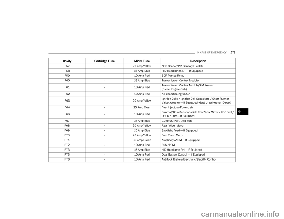
IN CASE OF EMERGENCY273
F57 –20 Amp Yellow NOX Sensor/PM Sensor/Fuel Htr
F58 –15 Amp Blue HID Headlamps LH — If Equipped
F59 –10 Amp Red SCR Pumps Relay
F60 –15 Amp Blue Transmission Control Module
F61 –10 Amp RedTransmission Control Module/PM Sensor
(Diesel Engine Only)
F62 –10 Amp Red Air Conditioning Clutch
F63 –20 Amp Yellow Ignition Coils / Ignition Coil Capacitors / Short Runner
Valve Actuator — If Equipped (Gas) Urea Heater (Diesel)
F64 –25 Amp Clear Fuel Injectors/Powertrain
F66 –10 Amp RedSunroof/Rain Sensor/Inside Rear View Mirror / USB Port /
DSCR / DTV — If Equipped
F67 –15 Amp Blue CDM/UCI Port/USB Port
F68 –20 Amp Yellow Rear Wiper Motor
F69 –15 Amp Blue Spotlight Feed — If Equipped
F70 –20 Amp Yellow Fuel Pump Motor
F71 –30 Amp Green Amplifier/ANCM — If Equipped
F72 –10 Amp Red ECM/PCM
F73 –15 Amp Blue HID Headlamp RH — If Equipped
F75 –10 Amp Red Dual Battery Control — If Equipped
F76 –10 Amp Red Anti-lock Brakes/Electronic Stability Control
CavityCartridge Fuse Micro Fuse Description
6
20_WD_OM_EN_USC_t.book Page 273