check engine DODGE DURANGO 2020 Owners Manual
[x] Cancel search | Manufacturer: DODGE, Model Year: 2020, Model line: DURANGO, Model: DODGE DURANGO 2020Pages: 464, PDF Size: 22.14 MB
Page 6 of 464
4
ONBOARD DIAGNOSTIC SYSTEM — OBD II .... 120 Onboard Diagnostic System
(OBD II) Cybersecurity ................................120
EMISSIONS INSPECTION AND
MAINTENANCE PROGRAMS ............................ 121
SAFETY
SAFETY FEATURES ............................................ 122
Anti-Lock Brake System (ABS) ................. 122
Electronic Brake Control (EBC) System ....123
AUXILIARY DRIVING SYSTEMS ........................ 131
Blind Spot Monitoring (BSM) —
If Equipped .................................................131 Forward Collision Warning (FCW) With
Mitigation ...................................................136 Tire Pressure Monitoring System
(TPMS) ........................................................ 138
OCCUPANT RESTRAINT SYSTEMS .................. 143
Occupant Restraint Systems Features.....143
Important Safety Precautions ...................143Seat Belt Systems ..................................... 144Supplemental Restraint Systems (SRS) ...153Child Restraints .........................................163
Transporting Pets ......................................180 SAFETY TIPS ....................................................... 180
Transporting Passengers .......................... 180Exhaust Gas .............................................. 180
Safety Checks You Should Make
Inside The Vehicle ..................................... 181 Periodic Safety Checks You Should Make
Outside The Vehicle ................................... 183STARTING AND OPERATING
STARTING THE ENGINE .....................................184
Automatic Transmission............................ 184
Keyless Enter-N-Go — Ignition ................... 184
Normal Starting ......................................... 185
If Engine Fails To Start ............................. 187Cold Weather Operation (Below –22°F
Or −30°C) ................................................. 188 After Starting .............................................. 188
ENGINE BLOCK HEATER — IF EQUIPPED ........188
ENGINE BREAK-IN RECOMMENDATIONS –
NON-SRT .............................................................. 188
ENGINE BREAK-IN RECOMMENDATIONS –
SRT ....................................................................... 189
PARKING BRAKE ............................................... 190 AUTOMATIC TRANSMISSION ........................... 191
Ignition Park Interlock ............................... 192Brake/Transmission Shift Interlock
System ....................................................... 192 Fuel Economy (ECO) Mode........................ 192
Eight-Speed Automatic Transmission ...... 193
SPORT MODE — IF EQUIPPED.......................... 199
ALL-WHEEL DRIVE OPERATION ....................... 199
Single-Speed Operating Instructions/
Precautions— If Equipped ........................ 199 Electronically Shifted Transfer Case
(Three-Position Switch) — If Equipped...... 199 Shifting Procedure ..................................... 201
FUEL SAVER TECHNOLOGY 5.7L/6.4L
ONLY — IF EQUIPPED ........................................ 202
POWER STEERING............................................. 202
STOP/START SYSTEM — IF EQUIPPED ........... 203 Automatic Mode ........................................ 203
Possible Reasons The Engine Does Not
Autostop ..................................................... 204 To Start The Engine While In Autostop
Mode .......................................................... 204 To Manually Turn Off The Stop/Start
System........................................................ 205 To Manually Turn On The Stop/Start
System........................................................ 205 System Malfunction................................... 205
20_WD_OM_EN_USC_t.book Page 4
Page 8 of 464
6
RECREATIONAL TOWING (BEHIND
MOTORHOME, ETC.) ......................................... 253 Towing This Vehicle Behind Another
Vehicle .......................................................253 Recreational Towing — Rear-Wheel
Drive Models ..............................................254 Recreational Towing — All Wheel Drive
Models (Single-Speed Transfer Case) ......254 Recreational Towing — All-Wheel Drive
Models (Two-Speed Transfer Case) ..........254
DRIVING TIPS ..................................................... 257
On-Road Driving Tips .................................257
Off-Road Driving Tips .................................258
IN CASE OF EMERGENCY
HAZARD WARNING FLASHERS ....................... 261
ASSIST AND SOS MIRROR — IF EQUIPPED.... 261General Information ..................................265
BULB REPLACEMENT ....................................... 266
Replacement Bulbs .................................266
Bulb Replacement ....................................268
FUSES .................................................................. 269
General Information ..................................270Underhood Fuses.......................................270 JACKING AND TIRE CHANGING .......................275
Run Flat Tires ............................................. 276
Jack Location ............................................. 276
Spare Tire Stowage ................................... 277
Spare Tire Removal ................................... 277
Preparations For Jacking .......................... 279Jacking Instructions .................................. 279Road Tire Installation ................................ 283
JUMP STARTING ................................................ 283
Preparations For Jump Start ..................... 284Jump Starting Procedure .......................... 285
REFUELING IN EMERGENCY –
IF EQUIPPED ...................................................... 286
IF YOUR ENGINE OVERHEATS .........................287
MANUAL PARK RELEASE .................................. 287
FREEING A STUCK VEHICLE .............................289
TOWING A DISABLED VEHICLE .......................290 Rear Wheel Drive Models.......................... 292All Wheel Drive Models.............................. 292
TOWING A DISABLED SRT VEHICLE ................293
ENHANCED ACCIDENT RESPONSE SYSTEM
(EARS) .................................................................293
EVENT DATA RECORDER (EDR) .......................293
SERVICING AND MAINTENANCE
SCHEDULED SERVICING — NON-SRT .............. 294
Maintenance Plan — Non-SRT .................. 294Heavy Duty Use Of The Vehicle................. 298
SCHEDULED SERVICING – SRT ....................... 298
Maintenance Plan — SRT .......................... 300
ENGINE COMPARTMENT .................................. 304
3.6L Engine ................................................ 304
5.7L Engine ................................................ 305
6.4L Engine ................................................ 306
Checking Oil Level ..................................... 307
Adding Washer Fluid ................................ 307
Maintenance-Free Battery ....................... 307Pressure Washing...................................... 308
DEALER SERVICE .............................................. 308
Engine Oil .................................................. 308
Engine Oil Filter ......................................... 311Engine Air Cleaner Filter............................ 311Air Conditioner Maintenance .................... 313Accessory Drive Belt Inspection ............... 315Body Lubrication ....................................... 316
Windshield Wiper Blades ......................... 316
Exhaust System ........................................ 320
Cooling System .......................................... 321
Brake System ............................................ 325Automatic Transmission............................ 326Front/Rear Axle Fluid ............................... 327Transfer Case ............................................ 327
20_WD_OM_EN_USC_t.book Page 6
Page 24 of 464
22GETTING TO KNOW YOUR VEHICLE
After placing the ignition in the ON/RUN
position, the vehicle security light will turn on for
three seconds for a bulb check. If the light
remains on after the bulb check, it indicates
that there is a problem with the electronics. In
addition, if the light begins to flash after the
bulb check, it indicates that someone used an
invalid key fob to start the engine. Either of
these conditions will result in the engine being
shut off after two seconds.
If the vehicle security light turns on during
normal vehicle operation (vehicle running for
longer than 10 seconds), it indicates that there
is a fault in the electronics. Should this occur,
have the vehicle serviced as soon as possible by
an authorized dealer.
All of the key fobs provided with your new
vehicle have been programmed to the vehicle
electronics.KEY PROGRAMMING
Programming key fobs may be performed at an
authorized dealer.
REPLACEMENT KEYS
NOTE:
Only key fobs that are programmed to the
vehicle electronics can be used to start and
operate the vehicle. Once a key fob is
programmed to a vehicle, it cannot be
programmed to any other vehicle.
NOTE:
Duplication of key fobs may be performed at an
authorized dealer. This procedure consists of
programming a blank key fob to the vehicle
electronics. A blank key fob is one that has
never been programmed. When having the Sentry Key Immobilizer system
serviced, bring all vehicle keys with you to an
authorized dealer.
GENERAL INFORMATION
The following regulatory statement applies to all
Radio Frequency (RF) devices equipped in this
vehicle:
This device complies with Part 15 of the FCC
Rules and with Innovation, Science and
Economic Development Canada license-exempt
RSS standard(s). Operation is subject to the
following two conditions:
1. This device may not cause harmful
interference, and
2. This device must accept any interference received, including interference that may
cause undesired operation.
CAUTION!
The Sentry Key Immobilizer system is not
compatible with some aftermarket remote
starting systems. Use of these systems may
result in vehicle starting problems and loss of
security protection.
CAUTION!
Always remove the key fobs from the
vehicle and lock all doors when leaving the
vehicle unattended.
For vehicles equipped with Keyless
Enter-N-Go — Ignition, always remember to
place the ignition in the OFF position.
20_WD_OM_EN_USC_t.book Page 22
Page 98 of 464
96GETTING TO KNOW YOUR INSTRUMENT PANEL
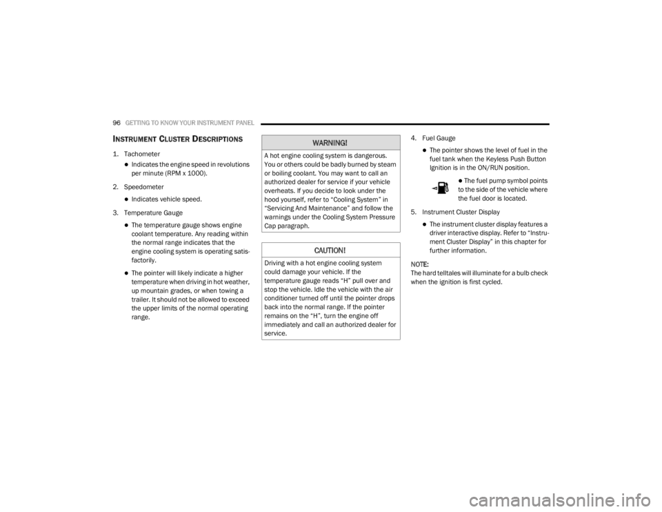
INSTRUMENT CLUSTER DESCRIPTIONS
1. Tachometer
Indicates the engine speed in revolutions
per minute (RPM x 1000).
2. Speedometer
Indicates vehicle speed.
3. Temperature Gauge
The temperature gauge shows engine
coolant temperature. Any reading within
the normal range indicates that the
engine cooling system is operating satis -
factorily.
The pointer will likely indicate a higher
temperature when driving in hot weather,
up mountain grades, or when towing a
trailer. It should not be allowed to exceed
the upper limits of the normal operating
range. 4. Fuel Gauge
The pointer shows the level of fuel in the
fuel tank when the Keyless Push Button
Ignition is in the ON/RUN position.
The fuel pump symbol points
to the side of the vehicle where
the fuel door is located.
5. Instrument Cluster Display
The instrument cluster display features a
driver interactive display. Refer to “Instru -
ment Cluster Display” in this chapter for
further information.
NOTE:
The hard telltales will illuminate for a bulb check
when the ignition is first cycled.
WARNING!
A hot engine cooling system is dangerous.
You or others could be badly burned by steam
or boiling coolant. You may want to call an
authorized dealer for service if your vehicle
overheats. If you decide to look under the
hood yourself, refer to “Cooling System” in
“Servicing And Maintenance” and follow the
warnings under the Cooling System Pressure
Cap paragraph.
CAUTION!
Driving with a hot engine cooling system
could damage your vehicle. If the
temperature gauge reads “H” pull over and
stop the vehicle. Idle the vehicle with the air
conditioner turned off until the pointer drops
back into the normal range. If the pointer
remains on the “H”, turn the engine off
immediately and call an authorized dealer for
service.
20_WD_OM_EN_USC_t.book Page 96
Page 100 of 464
98GETTING TO KNOW YOUR INSTRUMENT PANEL
SRT INSTRUMENT CLUSTER
D
ESCRIPTIONS
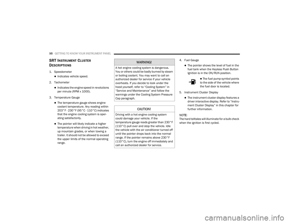
1. Speedometer
Indicates vehicle speed.
2. Tachometer
Indicates the engine speed in revolutions
per minute (RPM x 1000).
3. Temperature Gauge
The temperature gauge shows engine
coolant temperature. Any reading within
203°F - 230°F (95°C - 110°C) indicates
that the engine cooling system is oper -
ating satisfactorily.
The pointer will likely indicate a higher
temperature when driving in hot weather,
up mountain grades, or when towing a
trailer. It should not be allowed to exceed
the upper limits of the normal operating
range. 4. Fuel Gauge
The pointer shows the level of fuel in the
fuel tank when the Keyless Push Button
Ignition is in the ON/RUN position.
The fuel pump symbol points
to the side of the vehicle where
the fuel door is located.
5. Instrument Cluster Display
The instrument cluster display features a
driver interactive display. Refer to “Instru -
ment Cluster Display” in this chapter for
further information.
NOTE:
The hard telltales will illuminate for a bulb check
when the ignition is first cycled.
WARNING!
A hot engine cooling system is dangerous.
You or others could be badly burned by steam
or boiling coolant. You may want to call an
authorized dealer for service if your vehicle
overheats. If you decide to look under the
hood yourself, refer to “Cooling System” in
“Service and Maintenance” and follow the
warnings under the Cooling System Pressure
Cap paragraph.
CAUTION!
Driving with a hot engine cooling system
could damage your vehicle. If the
temperature gauge reads greater than 230°F
(110°C) pull over and stop the vehicle. Idle
the vehicle with the air conditioner turned off
until the pointer drops back into the normal
range. If the pointer remains above 230°F
(110°C), turn the engine off immediately and
call an authorized dealer for service.
20_WD_OM_EN_USC_t.book Page 98
Page 111 of 464
GETTING TO KNOW YOUR INSTRUMENT PANEL109
Installing options like additional lights,
upfitter electrical accessories, audio
systems, alarms and similar devices.
Unusual driving cycles (short trips separated
by long parking periods).
The vehicle was parked for an extended
period of time (weeks, months).
The battery was recently replaced and was
not charged completely.
The battery was discharged by an electrical
load left on when the vehicle was parked.
The battery was used for an extended period
with the engine not running to supply radio,
lights, chargers, +12 Volt portable appli-
ances like vacuum cleaners, game consoles
and similar devices. What to do when an electrical load reduction
action message is present (“Battery Saver On”
or “Battery Saver Mode”)
During a trip:
Reduce power to unnecessary loads if
possible:
Turn off redundant lights (interior or exte
-
rior)
Check what may be plugged in to power
outlets +12 Volt, 115 Volt AC, USB ports
Check HVAC settings (blower, tempera -
ture)
Check the audio settings (volume)
After a trip:
Check if any aftermarket equipment was
installed (additional lights, upfitter electrical
accessories, audio systems, alarms) and
review specifications if any (load and Ignition
Off Draw currents).
Evaluate the latest driving cycles (distance,
driving time and parking time).
The vehicle should have service performed if
the message is still present during consecu -
tive trips, and if the evaluation and driving
pattern of the vehicle did not help to identify
the cause.
WARNING LIGHTS AND MESSAGES
The warning/indicator lights will illuminate in
the instrument panel together with a dedicated
message and/or acoustic signal when
applicable. These indications are indicative and
precautionary and as such must not be
considered as exhaustive and/or alternative to
the information contained in the Owner’s
Manual, which you are advised to read carefully
in all cases. Always refer to the information in
this chapter in the event of a failure indication.
All active telltales will display first if applicable.
The system check menu may appear different
based upon equipment options and current
vehicle status. Some telltales are optional and
may not appear.3
20_WD_OM_EN_USC_t.book Page 109
Page 113 of 464
GETTING TO KNOW YOUR INSTRUMENT PANEL111
Vehicles equipped with the Anti-Lock Brake
System (ABS) are also equipped with Electronic
Brake Force Distribution (EBD). In the event of
an EBD failure, the Brake Warning Light will turn
on along with the ABS Light. Immediate repair to
the ABS system is required.
Operation of the Brake Warning Light can be
checked by turning the ignition switch from the
OFF position to the ON/RUN position. The light
should illuminate for approximately two
seconds. The light should then turn off unless
the parking brake is applied or a brake fault is
detected. If the light does not illuminate, have
the light inspected by an authorized dealer.
The light also will turn on when the parking
brake is applied with the ignition switch in the
ON/RUN position.
NOTE:
This light shows only that the parking brake is
applied. It does not show the degree of brake
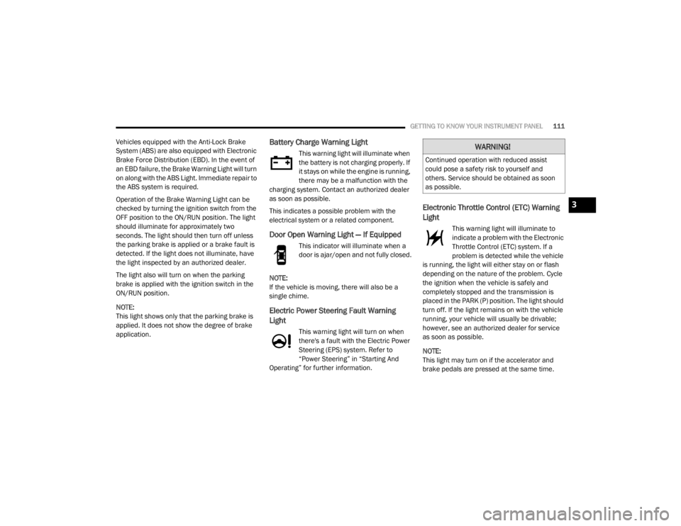
application.Battery Charge Warning Light
This warning light will illuminate when
the battery is not charging properly. If
it stays on while the engine is running,
there may be a malfunction with the
charging system. Contact an authorized dealer
as soon as possible.
This indicates a possible problem with the
electrical system or a related component.
Door Open Warning Light — If Equipped
This indicator will illuminate when a
door is ajar/open and not fully closed.
NOTE:
If the vehicle is moving, there will also be a
single chime.
Electric Power Steering Fault Warning
Light
This warning light will turn on when
there's a fault with the Electric Power
Steering (EPS) system. Refer to
“Power Steering” in “Starting And
Operating” for further information.
Electronic Throttle Control (ETC) Warning
Light
This warning light will illuminate to
indicate a problem with the Electronic
Throttle Control (ETC) system. If a
problem is detected while the vehicle
is running, the light will either stay on or flash
depending on the nature of the problem. Cycle
the ignition when the vehicle is safely and
completely stopped and the transmission is
placed in the PARK (P) position. The light should
turn off. If the light remains on with the vehicle
running, your vehicle will usually be drivable;
however, see an authorized dealer for service
as soon as possible.
NOTE:
This light may turn on if the accelerator and
brake pedals are pressed at the same time.
WARNING!
Continued operation with reduced assist
could pose a safety risk to yourself and
others. Service should be obtained as soon
as possible.
3
20_WD_OM_EN_USC_t.book Page 111
Page 114 of 464
112GETTING TO KNOW YOUR INSTRUMENT PANEL
If the light continues to flash when the vehicle is
running, immediate service is required and you
may experience reduced performance, an
elevated/rough idle, or engine stall and your
vehicle may require towing. The light will come
on when the ignition is placed in the ON/RUN or
ACC/ON/RUN position and remain on briefly as
a bulb check. If the light does not come on
during starting, have the system checked by an
authorized dealer.
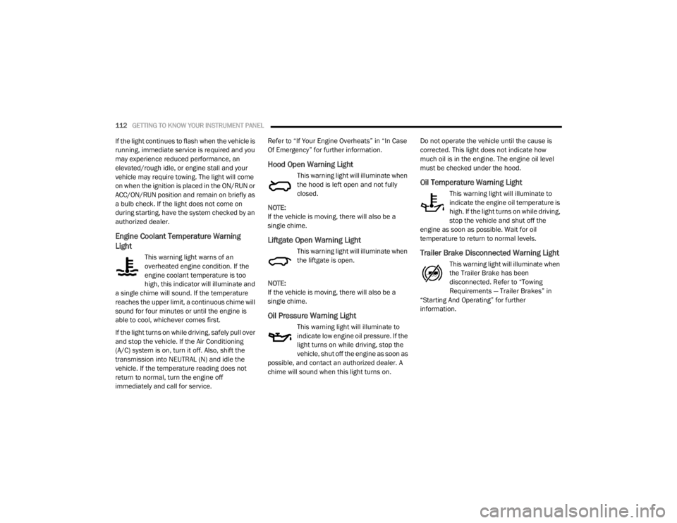
Engine Coolant Temperature Warning
Light
This warning light warns of an
overheated engine condition. If the
engine coolant temperature is too
high, this indicator will illuminate and
a single chime will sound. If the temperature
reaches the upper limit, a continuous chime will
sound for four minutes or until the engine is
able to cool, whichever comes first.
If the light turns on while driving, safely pull over
and stop the vehicle. If the Air Conditioning
(A/C) system is on, turn it off. Also, shift the
transmission into NEUTRAL (N) and idle the
vehicle. If the temperature reading does not
return to normal, turn the engine off
immediately and call for service. Refer to “If Your Engine Overheats” in “In Case
Of Emergency” for further information.
Hood Open Warning Light
This warning light will illuminate when
the hood is left open and not fully
closed.
NOTE:
If the vehicle is moving, there will also be a
single chime.
Liftgate Open Warning Light
This warning light will illuminate when
the liftgate is open.
NOTE:
If the vehicle is moving, there will also be a
single chime.
Oil Pressure Warning Light
This warning light will illuminate to
indicate low engine oil pressure. If the
light turns on while driving, stop the
vehicle, shut off the engine as soon as
possible, and contact an authorized dealer. A
chime will sound when this light turns on. Do not operate the vehicle until the cause is
corrected. This light does not indicate how
much oil is in the engine. The engine oil level
must be checked under the hood.
Oil Temperature Warning Light
This warning light will illuminate to
indicate the engine oil temperature is
high. If the light turns on while driving,
stop the vehicle and shut off the
engine as soon as possible. Wait for oil
temperature to return to normal levels.
Trailer Brake Disconnected Warning Light
This warning light will illuminate when
the Trailer Brake has been
disconnected. Refer to “Towing
Requirements — Trailer Brakes” in
“Starting And Operating” for further
information.
20_WD_OM_EN_USC_t.book Page 112
Page 115 of 464
GETTING TO KNOW YOUR INSTRUMENT PANEL113
Transmission Temperature Warning Light
— If Equipped
This warning light will illuminate to
warn of a high transmission fluid
temperature. This may occur with
strenuous usage such as trailer
towing. If this light turns on, stop the vehicle and
run the engine at idle or slightly faster, with the
transmission in PARK (P) or NEUTRAL (N), until
the light turns off. Once the light turns off, you
may continue to drive normally.
Vehicle Security Warning Light — If
Equipped
This light will flash at a fast rate for
approximately 15 seconds when the
vehicle security alarm is arming, and
then will flash slowly until the vehicle
is disarmed.
YELLOW WARNING LIGHTS
Engine Check/Malfunction Indicator
Warning Light (MIL)
The Engine Check/Malfunction
Indicator Light (MIL) is a part of an
Onboard Diagnostic System called
OBD II that monitors engine and
automatic transmission control systems. This
warning light will illuminate when the ignition is
in the ON/RUN position before engine start. If
the bulb does not come on when turning the
ignition switch from OFF to ON/RUN, have the
condition checked promptly. Certain conditions, such as a loose or missing
gas cap, poor quality fuel, etc., may illuminate
the light after engine start. The vehicle should
be serviced if the light stays on through several
typical driving styles. In most situations, the
vehicle will drive normally and will not require
towing.
When the engine is running, the MIL may flash
to alert serious conditions that could lead to
immediate loss of power or severe catalytic
converter damage. The vehicle should be
serviced by an authorized dealer as soon as
possible if this occurs.WARNING!
If you continue operating the vehicle when
the Transmission Temperature Warning Light
is illuminated you could cause the fluid to boil
over, come in contact with hot engine or
exhaust components and cause a fire.
CAUTION!
Continuous driving with the Transmission
Temperature Warning Light illuminated will
eventually cause severe transmission
damage or transmission failure.
WARNING!
A malfunctioning catalytic converter, as
referenced above, can reach higher
temperatures than in normal operating
conditions. This can cause a fire if you drive
slowly or park over flammable substances
such as dry plants, wood, cardboard, etc. This
could result in death or serious injury to the
driver, occupants or others.
3
20_WD_OM_EN_USC_t.book Page 113
Page 123 of 464
GETTING TO KNOW YOUR INSTRUMENT PANEL121
EMISSIONS INSPECTION AND
MAINTENANCE PROGRAMS
In some localities, it may be a legal requirement
to pass an inspection of your vehicle's
emissions control system. Failure to pass could
prevent vehicle registration.
For states that require an Inspection
and Maintenance (I/M), this check
verifies the “Malfunction Indicator
Light (MIL)” is functioning and is not
on when the engine is running, and that the
OBD II system is ready for testing.
Normally, the OBD II system will be ready. The
OBD II system may not be ready if your vehicle
was recently serviced, recently had a depleted
battery or a battery replacement. If the OBD II
system should be determined not ready for the
I/M test, your vehicle may fail the test.
Your vehicle has a simple ignition actuated test,
which you can use prior to going to the test
station. To check if your vehicle's OBD II system
is ready, you must do the following:
1. Cycle the ignition switch to the ON position,
but do not crank or start the engine.
NOTE:
If you crank or start the engine, you will have to
start this test over.
2. As soon as you cycle the ignition switch to the ON position, you will see the
Malfunction Indicator Light (MIL) symbol
come on as part of a normal bulb check.
3. Approximately 15 seconds later, one of two things will happen:
The MIL will flash for about 10 seconds
and then return to being fully illuminated
until you turn OFF the ignition or start the
engine. This means that your vehicle's
OBD II system is not ready and you
should not proceed to the I/M station.
The MIL will not flash at all and will
remain fully illuminated until you place
the ignition in the off position or start the
engine. This means that your vehicle's
OBD II system is ready and you can
proceed to the I/M station. If your OBD II system is not ready,
you should
see an authorized dealer or repair facility. If your
vehicle was recently serviced or had a battery
failure or replacement, you may need to do
nothing more than drive your vehicle as you
normally would in order for your OBD II system
to update. A recheck with the above test routine
may then indicate that the system is now ready.
Regardless of whether your vehicle's OBD II
system is ready or not, if the MIL is illuminated
during normal vehicle operation you should
have your vehicle serviced before going to the
I/M station. The I/M station can fail your vehicle
because the MIL is on with the engine running.
3
20_WD_OM_EN_USC_t.book Page 121