steering DODGE DURANGO 2021 Workshop Manual
[x] Cancel search | Manufacturer: DODGE, Model Year: 2021, Model line: DURANGO, Model: DODGE DURANGO 2021Pages: 340, PDF Size: 20.38 MB
Page 224 of 340
222SAFETY
(Continued)
Cut off battery power to the:
Engine
Electric Motor (if equipped)
Electric power steering
Brake booster
Electric park brake
Automatic transmission gear selector
Horn
Front wiper
Headlamp washer pump
NOTE:After an accident, remember to cycle the ignition to
the STOP (OFF/LOCK) position and remove the key
from the ignition switch to avoid draining the
battery. Carefully check the vehicle for fuel leaks in
the engine compartment and on the ground near
the engine compartment and fuel tank before
resetting the system and starting the engine. If
there are no fuel leaks or damage to the vehicle
electrical devices (e.g. headlights) after an
accident, reset the system by following the
procedure described below. If you have any doubt,
contact an authorized dealer.
Enhanced Accident Response System
Reset Procedure
In order to reset the Enhanced Accident Response
System functions after an event, the ignition switch
must be changed from ignition START or ON/RUN
to ignition OFF. Carefully check the vehicle for fuel
leaks in the engine compartment and on the
ground near the engine compartment and fuel
tank before resetting the system and starting the
engine.
After an accident, if the vehicle will not start after
performing the reset procedure, the vehicle must
be towed to an authorized dealer to be inspected
and to have the Enhanced Accident Response
System reset.
Maintaining Your Air Bag System Event Data Recorder (EDR)
This vehicle is equipped with an event data
recorder (EDR). The main purpose of an EDR is to
record, in certain crash or near crash-like
situations, such as an air bag deployment or hitting
a road obstacle, data that will assist in
understanding how a vehicle’s systems performed.
The EDR is designed to record data related to
WARNING!
Modifications to any part of the air bag system
could cause it to fail when you need it. You
could be injured if the air bag system is not
there to protect you. Do not modify the compo-
nents or wiring, including adding any kind of
badges or stickers to the steering wheel hub
trim cover or the upper passenger side of the
instrument panel. Do not modify the front
fascia/bumper, vehicle body structure, or add
aftermarket side steps or running boards.
It is dangerous to try to repair any part of the
air bag system yourself. Be sure to tell anyone
who works on your vehicle that it has an air
bag system.
Do not attempt to modify any part of your air
bag system. The air bag may inflate acciden -
tally or may not function properly if modifica -
tions are made. Take your vehicle to an
authorized dealer for any air bag system
service. If your seat, including your trim cover
and cushion, needs to be serviced in any way
(including removal or loosening/tightening of
seat attachment bolts), take the vehicle to an
authorized dealer. Only manufacturer
approved seat accessories may be used. If it is
necessary to modify the air bag system for
persons with disabilities, contact an autho -
rized dealer.
WARNING!
21_WD_OM_EN_USC_t.book Page 222
Page 245 of 340
243
IN CASE OF EMERGENCY
HAZARD WARNING FLASHERS
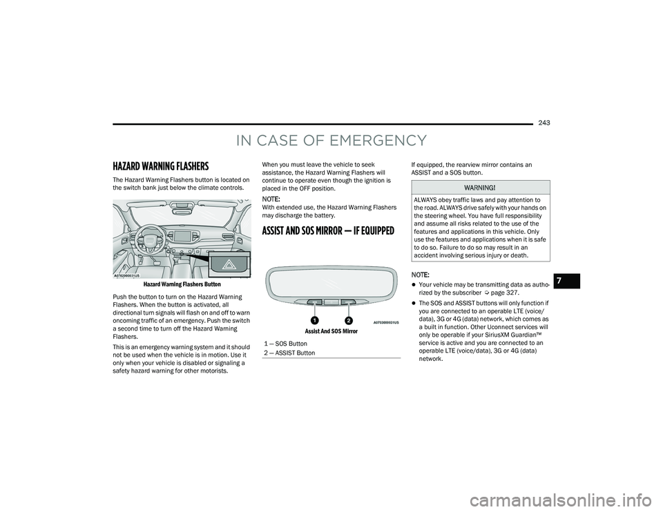
The Hazard Warning Flashers button is located on
the switch bank just below the climate controls.
Hazard Warning Flashers Button
Push the button to turn on the Hazard Warning
Flashers. When the button is activated, all
directional turn signals will flash on and off to warn
oncoming traffic of an emergency. Push the switch
a second time to turn off the Hazard Warning
Flashers.
This is an emergency warning system and it should
not be used when the vehicle is in motion. Use it
only when your vehicle is disabled or signaling a
safety hazard warning for other motorists. When you must leave the vehicle to seek
assistance, the Hazard Warning Flashers will
continue to operate even though the ignition is
placed in the OFF position.
NOTE:With extended use, the Hazard Warning Flashers
may discharge the battery.
ASSIST AND SOS MIRROR — IF EQUIPPED
Assist And SOS Mirror
If equipped, the rearview mirror contains an
ASSIST and a SOS button.
NOTE:
Your vehicle may be transmitting data as autho
-
rized by the subscriber Ú page 327.
The SOS and ASSIST buttons will only function if
you are connected to an operable LTE (voice/
data), 3G or 4G (data) network, which comes as
a built in function. Other Uconnect services will
only be operable if your SiriusXM Guardian™
service is active and you are connected to an
operable LTE (voice/data), 3G or 4G (data)
network.
1 — SOS Button
2 — ASSIST Button
WARNING!
ALWAYS obey traffic laws and pay attention to
the road. ALWAYS drive safely with your hands on
the steering wheel. You have full responsibility
and assume all risks related to the use of the
features and applications in this vehicle. Only
use the features and applications when it is safe
to do so. Failure to do so may result in an
accident involving serious injury or death.
7
21_WD_OM_EN_USC_t.book Page 243
Page 246 of 340
244IN CASE OF EMERGENCY
ASSIST Call
The ASSIST Button is used to automatically
connect you to any one of the following support
centers:
Roadside Assistance – If you get a flat tire, or
need a tow, just push the ASSIST button and you
will be connected to a representative for assis-
tance. Roadside Assistance will know what
vehicle you’re driving and its location. Additional
fees may apply for roadside assistance.
SiriusXM Guardian™ Customer Care – In-vehicle
support for SiriusXM Guardian™.
Vehicle Customer Care – Total support for all
other vehicle issues.
Uconnect Customer Care - Total support for
Radio, Phone and NAV issues.
SOS Call
1. Push the SOS Call button on the Rearview Mirror.
NOTE:In case the SOS Call button is pushed in error,
there will be a 10 second delay before the SOS Call
system initiates a call to a SOS operator. To cancel
the SOS Call connection, push the SOS call button
on the Rearview Mirror or press the cancellation
button on the Device Screen. Termination of the
SOS Call will turn off the green LED light on the
Rearview Mirror. 2. The LED light located between the ASSIST and
SOS buttons on the Rearview Mirror will turn
green once a connection to a SOS operator has
been made.
3. Once a connection between the vehicle and a SOS operator is made, the SOS Call system
may transmit the following important vehicle
information to a SOS operator:
Indication that the occupant placed a
SOS Call
The vehicle brand
The last known GPS coordinates of the
vehicle
4. You should be able to speak with the SOS operator through the vehicle audio system to
determine if additional assistance is needed.
NOTE:
Your vehicle may be transmitting data as
authorized by the subscriber.
Once a connection is made between the
vehicle’s SOS Call system and the SOS oper -
ator, the SOS operator may be able to open
a voice connection with the vehicle to deter -
mine if additional assistance is needed.
Once the SOS operator opens a voice
connection with the vehicle’s SOS Call
system, the operator should be able to
speak with you or other vehicle occupants
and hear sounds occurring in the vehicle.
The vehicle’s SOS Call system will attempt
to remain connected with the SOS operator
until the SOS operator terminates the
connection.
5. The SOS operator may attempt to contact appropriate emergency responders and
provide them with important vehicle
information and GPS coordinates.
WARNING!
ALWAYS obey traffic laws and pay attention to
the road. ALWAYS drive safely with your hands on
the steering wheel. You have full responsibility
and assume all risks related to the use of the
features and applications in this vehicle. Only
use the features and applications when it is safe
to do so. Failure to do so may result in an
accident involving serious injury or death.
21_WD_OM_EN_USC_t.book Page 244
Page 248 of 340
246IN CASE OF EMERGENCY
Even if the SOS Call system is fully functional,
factors beyond FCA US LLC’s control may prevent
or stop the SOS Call system operation. These
include, but are not limited to, the following
factors:
The ignition is in the OFF position
The vehicle’s electrical systems are not intact
The SOS Call system software and/or hardware
are damaged during a crash
The vehicle battery loses power or becomes
disconnected during a vehicle crash
LTE (voice/data), 3G or 4G (data) network and/
or Global Positioning Satellite signals are
unavailable or obstructed
Equipment malfunction at the SOS operator
facility
Operator error by the SOS operator
LTE (voice/data), 3G or 4G (data) network
congestion
Weather
Buildings, structures, geographic terrain, or
tunnels
NOTE:
Your vehicle may be transmitting data as autho -
rized by the subscriber.
Never place anything on or near the vehicle’s
LTE (voice/data), 3G or 4G (data) and GPS
antennas. You could prevent LTE (voice/data),
3G or 4G (data) and GPS signal reception, which
can prevent your vehicle from placing an emer -
gency call. An operable LTE (voice/data), 3G or
4G (data) network connection and a GPS signal
is required for the SOS Call system to function
properly.
NOTE:Changes or modifications not expressly approved
by the party responsible for compliance could void
the user's authority to operate the equipment.
Automatic SOS — If Equipped
Automatic SOS is a hands-free safety service that
can immediately connect you with help in the event
that your vehicle’s airbags deploy. Please refer to
your provided radio supplement for complete
information.WARNING!
ALWAYS obey traffic laws and pay attention to
the road. ALWAYS drive safely with your hands on
the steering wheel. You have full responsibility
and assume all risks related to the use of the
features and applications in this vehicle. Only
use the features and applications when it is safe
to do so. Failure to do so may result in an
accident involving serious injury or death.
CAUTION!
To avoid damage to the mirror during cleaning,
never spray any cleaning solution directly onto
the mirror. Apply the solution onto a clean cloth
and wipe the mirror clean.
21_WD_OM_EN_USC_t.book Page 246
Page 262 of 340
260IN CASE OF EMERGENCY
2. Once the tension has been released and the lever has been unlocked, be sure it is stowed
properly and locks into position.
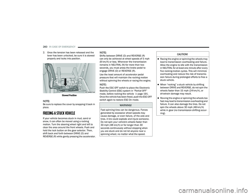
Stowed Position
NOTE:Be sure to replace the cover by snapping it back in
place.
FREEING A STUCK VEHICLE
If your vehicle becomes stuck in mud, sand or
snow, it can often be moved using a rocking
motion. Turn the steering wheel right and left to
clear the area around the front wheels. Push and
hold the lock button on the gear selector. Then,
shift back and forth between DRIVE (D) and
REVERSE (R) while gently pressing the accelerator.
NOTE:Shifts between DRIVE (D) and REVERSE (R)
can only be achieved at wheel speeds of 5 mph
(8 km/h) or less. Whenever the transmission
remains in NEUTRAL (N) for more than two
seconds, you must press the brake pedal to
engage DRIVE (D) or REVERSE (R).
Use the least amount of accelerator pedal
pressure that will maintain the rocking motion
without spinning the wheels or racing the engine.
NOTE:Push the ESC OFF switch to place the Electronic
Stability Control (ESC) system in “Partial OFF”
mode, before rocking the vehicle Ú page 191.
Once the vehicle has been freed, push the ESC OFF
switch again to restore ESC On mode.
WARNING!
Fast spinning tires can be dangerous. Forces
generated by excessive wheel speeds may
cause damage, or even failure, of the axle and
tires. A tire could explode and injure someone.
Do not spin your vehicle's wheels faster than
30 mph (48 km/h) or for longer than 30
seconds continuously without stopping when
you are stuck and do not let anyone near a
spinning wheel, no matter what the speed.
CAUTION!
Racing the engine or spinning the wheels may
lead to transmission overheating and failure.
Allow the engine to idle with the transmission
in NEUTRAL for at least one minute after every
five rocking-motion cycles. This will minimize
overheating and reduce the risk of transmis -
sion failure during prolonged efforts to free a
stuck vehicle.
When “rocking” a stuck vehicle by shifting
between DRIVE and REVERSE, do not spin the
wheels faster than 15 mph (24 km/h), or
drivetrain damage may result.
Revving the engine or spinning the wheels too
fast may lead to transmission overheating and
failure. It can also damage the tires. Do not
spin the wheels above 30 mph (48 km/h)
while in gear (no transmission shifting occur -
ring).
21_WD_OM_EN_USC_t.book Page 260
Page 264 of 340
262IN CASE OF EMERGENCY
Proper towing or lifting equipment is required to
prevent damage to your vehicle. Use only tow bars
and other equipment designed for this purpose,
following equipment manufacturer’s instructions.
Use of safety chains is mandatory. Attach a tow bar
or other towing device to main structural members
of the vehicle, not to fascia/bumpers or associated
brackets. State and local laws regarding vehicles
under tow must be observed.
If you must use the accessories (wipers,
defrosters, etc.) while being towed, the ignition
must be in the ON/RUN mode, not the ACC mode.
If the vehicle's battery is discharged, instructions
on shifting the automatic transmission out of PARK
(P) in order to move the vehicle can be found on
Ú page 258.
REAR WHEEL DRIVE MODELS
FCA US LLC recommends towing your vehicle with
all four wheels OFF the ground using a flatbed.
If flatbed equipment is not available, and the
transmission is operable, the vehicle may be towed
(with rear wheels on the ground) under the
following conditions:
The transmission must be in NEUTRAL (N).
For instructions on shifting the transmission to
NEUTRAL (N) when the engine is off
Ú page 258.
The towing speed must not exceed
30 mph (48 km/h).
The towing distance must not exceed
30 miles (48 km). If the transmission is not operable, or the vehicle
must be towed faster than 30 mph (48 km/h) or
farther than 30 miles (48 km), tow with the rear
wheels
OFF the ground. Acceptable methods are to
tow the vehicle on a flatbed, or with the front
wheels raised and the rear wheels on a towing
dolly, or (when using a suitable steering wheel
stabilizer to hold the front wheels in the straight
position) with the rear wheels raised and the front
wheels ON the ground.
CAUTION!
Do not use sling type equipment when towing.
Vehicle damage may occur.
When securing the vehicle to a flat bed truck,
do not attach to front or rear suspension
components. Damage to your vehicle may
result from improper towing.
CAUTION!
Towing faster than 30 mph (48 km/h) or
farther than 30 miles (48 km) with rear
wheels on the ground can cause severe trans -
mission damage. Damage from improper
towing is not covered under the New Vehicle
Limited Warranty.
21_WD_OM_EN_USC_t.book Page 262
Page 288 of 340
286SERVICING AND MAINTENANCE
(Continued)
FUSES
General Information
The fuses protect electrical systems against
excessive current.
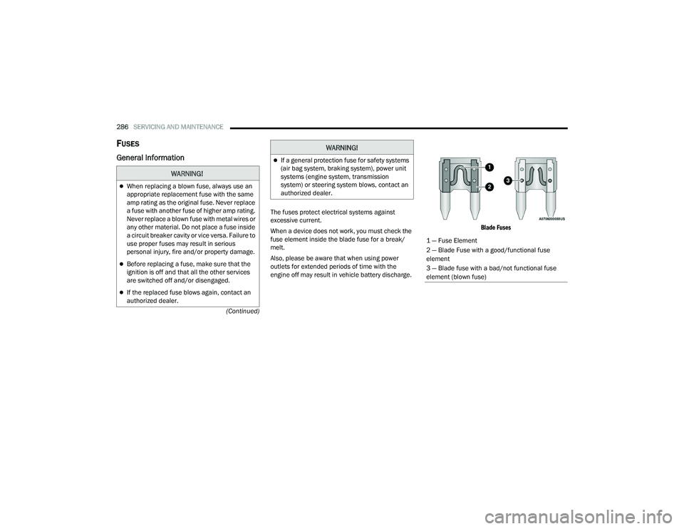
When a device does not work, you must check the
fuse element inside the blade fuse for a break/
melt.
Also, please be aware that when using power
outlets for extended periods of time with the
engine off may result in vehicle battery discharge.
Blade Fuses
WARNING!
When replacing a blown fuse, always use an
appropriate replacement fuse with the same
amp rating as the original fuse. Never replace
a fuse with another fuse of higher amp rating.
Never replace a blown fuse with metal wires or
any other material. Do not place a fuse inside
a circuit breaker cavity or vice versa. Failure to
use proper fuses may result in serious
personal injury, fire and/or property damage.
Before replacing a fuse, make sure that the
ignition is off and that all the other services
are switched off and/or disengaged.
If the replaced fuse blows again, contact an
authorized dealer.
If a general protection fuse for safety systems
(air bag system, braking system), power unit
systems (engine system, transmission
system) or steering system blows, contact an
authorized dealer.
WARNING!
1 — Fuse Element
2 — Blade Fuse with a good/functional fuse
element
3 — Blade fuse with a bad/not functional fuse
element (blown fuse)
21_WD_OM_EN_USC_t.book Page 286
Page 291 of 340
SERVICING AND MAINTENANCE289
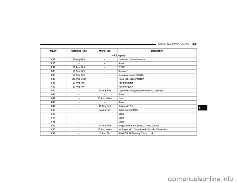
F32 30 Amp Pink –Drive Train Control Module
F33 ––Spare
F34 30 Amp Pink –ELSD*
F35 30 Amp Pink –Sunroof*
F36 30 Amp Pink –Electronic BackLight (EBL)
F37 25 Amp Clear –HVAC Rear Blower Motor*
F38 30 Amp Pink –Power Inverter
F39 30 Amp Pink –Power Liftgate
F40 –10 Amp Red Daytime Running Lights/Headlamp Leveling*
F41 ––Spare
F42 –20 Amp Yellow Horn
F43 ––Spare
F44 –10 Amp Red Diagnostic Port
F45 –5 Amp Tan Cyber Security MOD
F46 ––Spare
F47 ––Spare
F48 ––Spare
F49 –10 Amp Red Integrated Central Stack/Climate Control
F50 –20 Amp Yellow Air Suspension Control Module*/Slip Differential*
F51 –15 Amp Blue KIN/RF HUB/Steering Column Lock *
CavityCartridge Fuse Micro Fuse Description
* If Equipped
8
21_WD_OM_EN_USC_t.book Page 289
Page 293 of 340
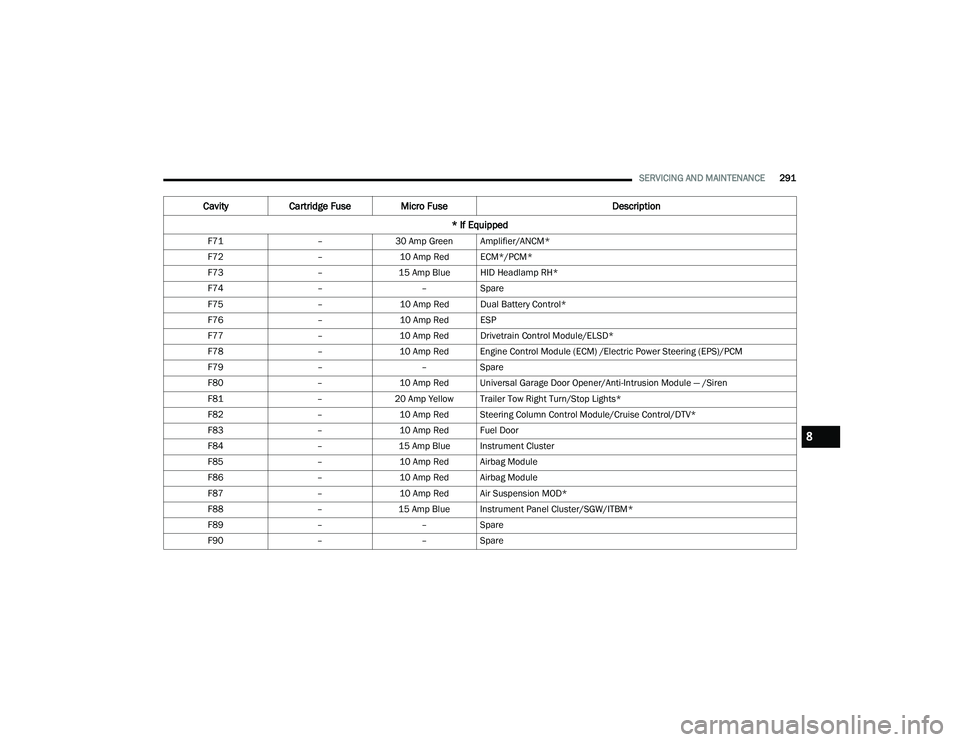
SERVICING AND MAINTENANCE291
F71 –30 Amp Green Amplifier/ANCM*
F72 –10 Amp Red ECM*/PCM*
F73 –15 Amp Blue HID Headlamp RH*
F74 ––Spare
F75 –10 Amp Red Dual Battery Control*
F76 –10 Amp Red ESP
F77 –10 Amp Red Drivetrain Control Module/ELSD*
F78 –10 Amp Red Engine Control Module (ECM) /Electric Power Steering (EPS)/PCM
F79 ––Spare
F80 –10 Amp Red Universal Garage Door Opener/Anti-Intrusion Module — /Siren
F81 –20 Amp Yellow Trailer Tow Right Turn/Stop Lights*
F82 –10 Amp Red Steering Column Control Module/Cruise Control/DTV*
F83 –10 Amp Red Fuel Door
F84 –15 Amp Blue Instrument Cluster
F85 –10 Amp Red Airbag Module
F86 –10 Amp Red Airbag Module
F87 –10 Amp Red Air Suspension MOD*
F88 –15 Amp Blue Instrument Panel Cluster/SGW/ITBM*
F89 ––Spare
F90 ––Spare
Cavity Cartridge Fuse Micro Fuse Description
* If Equipped
8
21_WD_OM_EN_USC_t.book Page 291
Page 294 of 340
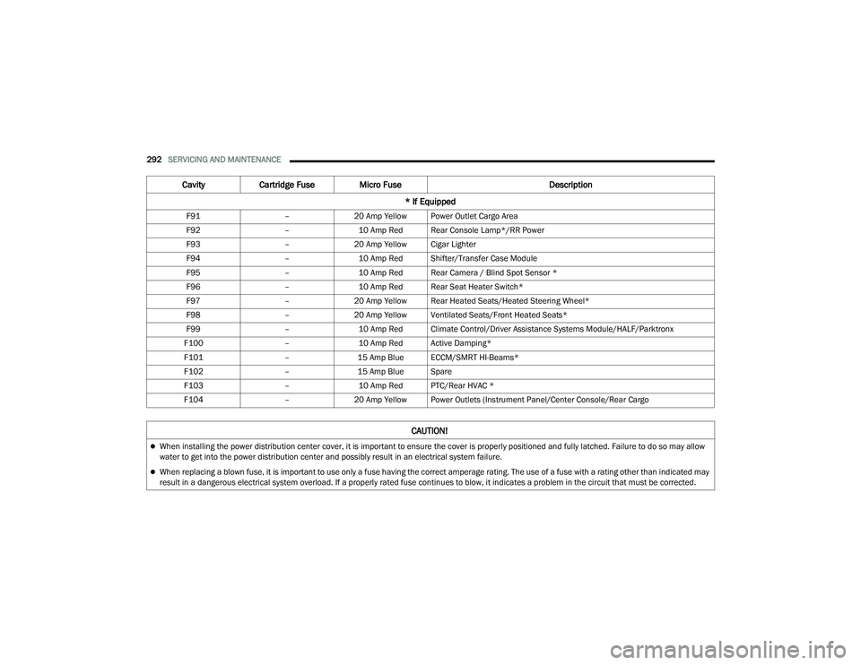
292SERVICING AND MAINTENANCE
F91 –20 Amp Yellow Power Outlet Cargo Area
F92 –10 Amp Red Rear Console Lamp*/RR Power
F93 –20 Amp Yellow Cigar Lighter
F94 –10 Amp Red Shifter/Transfer Case Module
F95 –10 Amp Red Rear Camera / Blind Spot Sensor *
F96 –10 Amp Red Rear Seat Heater Switch*
F97 –20 Amp Yellow Rear Heated Seats/Heated Steering Wheel*
F98 –20 Amp Yellow Ventilated Seats/Front Heated Seats*
F99 –10 Amp Red Climate Control/Driver Assistance Systems Module/HALF/Parktronx
F100 –10 Amp Red Active Damping*
F101 –15 Amp Blue ECCM/SMRT HI-Beams*
F102 –15 Amp Blue Spare
F103 –10 Amp Red PTC/Rear HVAC *
F104 –20 Amp Yellow Power Outlets (Instrument Panel/Center Console/Rear Cargo
Cavity Cartridge Fuse Micro Fuse Description
* If Equipped
CAUTION!
When installing the power distribution center cover, it is important to ensure the cover is properly positioned and fully latched. Failure to do so may allow
water to get into the power distribution center and possibly result in an electrical system failure.
When replacing a blown fuse, it is important to use only a fuse having the correct amperage rating. The use of a fuse with a rating other than indicated may
result in a dangerous electrical system overload. If a properly rated fuse continues to blow, it indicates a problem in the circuit that must be corrected.
21_WD_OM_EN_USC_t.book Page 292