warning light DODGE DURANGO 2021 Owners Manual
[x] Cancel search | Manufacturer: DODGE, Model Year: 2021, Model line: DURANGO, Model: DODGE DURANGO 2021Pages: 340, PDF Size: 20.38 MB
Page 5 of 340
3
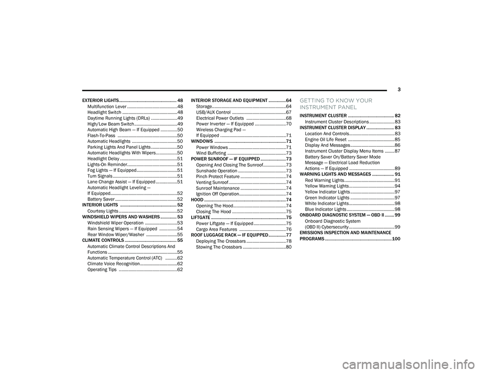
EXTERIOR LIGHTS.................................................. 48 Multifunction Lever ..........................................48
Headlight Switch ..............................................48
Daytime Running Lights (DRLs) ......................49
High/Low Beam Switch....................................49
Automatic High Beam — If Equipped ..............50
Flash-To-Pass ..................................................50
Automatic Headlights ......................................50
Parking Lights And Panel Lights ......................50
Automatic Headlights With Wipers..................50
Headlight Delay ................................................51
Lights-On Reminder..........................................51
Fog Lights — If Equipped ..................................51
Turn Signals ......................................................51
Lane Change Assist — If Equipped ..................51
Automatic Headlight Leveling —
If Equipped........................................................52
Battery Saver ....................................................52
INTERIOR LIGHTS ................................................. 52
Courtesy Lights .................................................52
WINDSHIELD WIPERS AND WASHERS .............. 53
Windshield Wiper Operation ...........................53
Rain Sensing Wipers — If Equipped ...............54
Rear Window Wiper/Washer ..........................55
CLIMATE CONTROLS ............................................. 55
Automatic Climate Control Descriptions And
Functions ..........................................................55
Automatic Temperature Control (ATC) ..........62
Climate Voice Recognition ...............................62
Operating Tips .................................................62 INTERIOR STORAGE AND EQUIPMENT ............... 64
Storage..............................................................64
USB/AUX Control .............................................67
Electrical Power Outlets .................................68
Power Inverter — If Equipped ..........................70
Wireless Charging Pad —
If Equipped .......................................................71
WINDOWS ..............................................................71
Power Windows ................................................71
Wind Buffeting .................................................73
POWER SUNROOF — IF EQUIPPED ...................... 73
Opening And Closing The Sunroof...................73
Sunshade Operation ........................................73
Pinch Protect Feature ......................................74
Venting Sunroof................................................74
Sunroof Maintenance ......................................74
Ignition Off Operation.......................................74
HOOD .......................................................................74
Opening The Hood............................................74
Closing The Hood .............................................75
LIFTGATE ................................................................. 75
Power Liftgate — If Equipped ...........................75
Cargo Area Features .......................................76
ROOF LUGGAGE RACK — IF EQUIPPED ............... 77
Deploying The Crossbars .................................78
Stowing The Crossbars ....................................80
GETTING TO KNOW YOUR
INSTRUMENT PANEL
INSTRUMENT CLUSTER ........................................ 82Instrument Cluster Descriptions ..................... 83
INSTRUMENT CLUSTER DISPLAY ........................ 83
Location And Controls...................................... 83
Engine Oil Life Reset ....................................... 85
Display And Messages ..................................... 86
Instrument Cluster Display Menu Items ........ 87
Battery Saver On/Battery Saver Mode
Message — Electrical Load Reduction
Actions — If Equipped ...................................... 89
WARNING LIGHTS AND MESSAGES ................... 91
Red Warning Lights ..........................................91
Yellow Warning Lights ...................................... 94
Yellow Indicator Lights ..................................... 97
Green Indicator Lights ..................................... 97
White Indicator Lights ...................................... 98
Blue Indicator Lights ........................................ 98
ONBOARD DIAGNOSTIC SYSTEM — OBD II ........ 99
Onboard Diagnostic System
(OBD II) Cybersecurity ...................................... 99
EMISSIONS INSPECTION AND MAINTENANCE
PROGRAMS .......................................................... 100
21_WD_OM_EN_USC_t.book Page 3
Page 12 of 340
10
VEHICLE MODIFICATIONS/ALTERATIONS
SYMBOL GLOSSARY
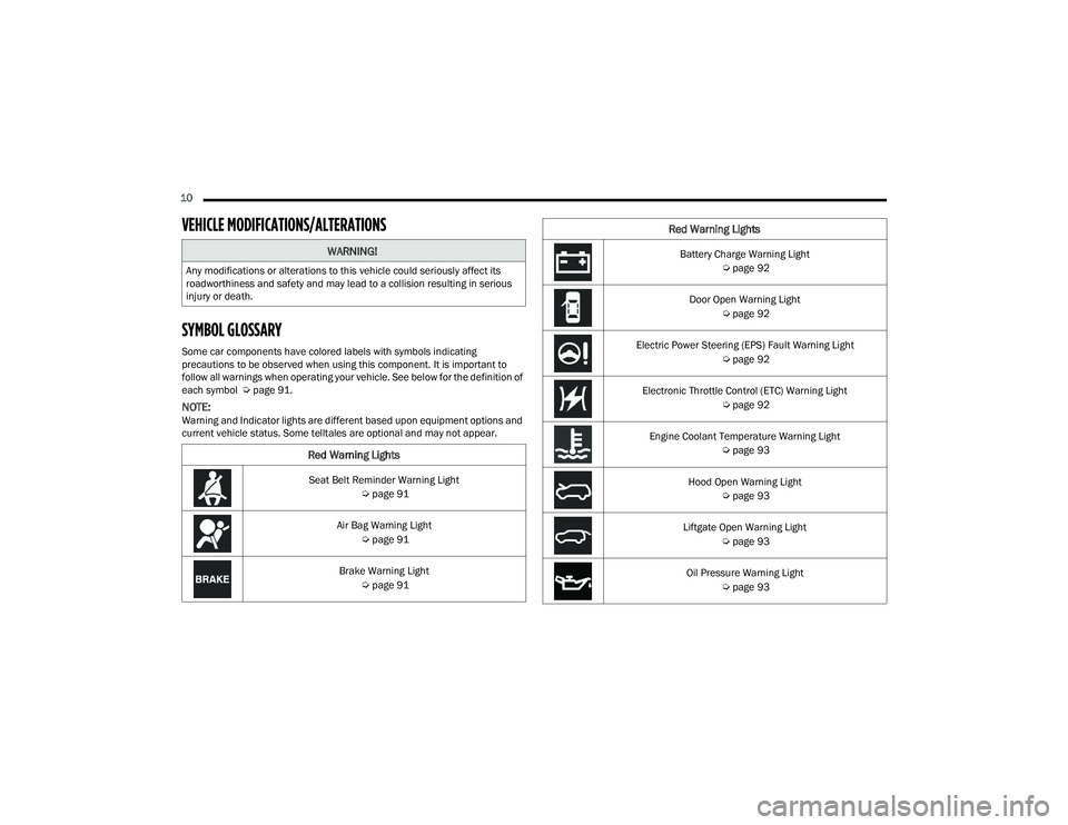
Some car components have colored labels with symbols indicating
precautions to be observed when using this component. It is important to
follow all warnings when operating your vehicle. See below for the definition of
each symbol Úpage 91.
NOTE:Warning and Indicator lights are different based upon equipment options and
current vehicle status. Some telltales are optional and may not appear.
WARNING!
Any modifications or alterations to this vehicle could seriously affect its
roadworthiness and safety and may lead to a collision resulting in serious
injury or death.
Red Warning Lights
Seat Belt Reminder Warning Light
Úpage 91
Air Bag Warning Light Úpage 91
Brake Warning Light Úpage 91
Battery Charge Warning Light
Úpage 92
Door Open Warning Light Úpage 92
Electric Power Steering (EPS) Fault Warning Light Úpage 92
Electronic Throttle Control (ETC) Warning Light Úpage 92
Engine Coolant Temperature Warning Light Úpage 93
Hood Open Warning Light Úpage 93
Liftgate Open Warning Light Úpage 93
Oil Pressure Warning Light Úpage 93
Red Warning Lights
21_WD_OM_EN_USC_t.book Page 10
Page 13 of 340
11
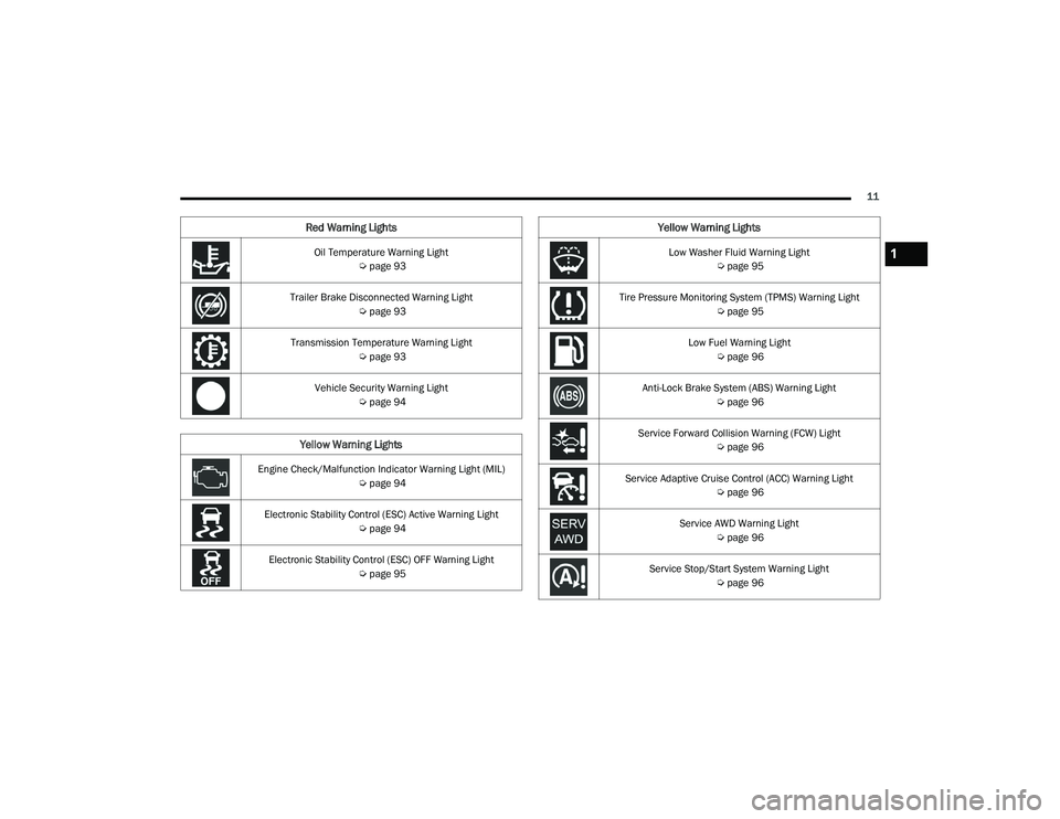
Oil Temperature Warning Light Úpage 93
Trailer Brake Disconnected Warning Light Úpage 93
Transmission Temperature Warning Light Úpage 93
Vehicle Security Warning Light Úpage 94
Yellow Warning Lights
Engine Check/Malfunction Indicator Warning Light (MIL)
Úpage 94
Electronic Stability Control (ESC) Active Warning Light Úpage 94
Electronic Stability Control (ESC) OFF Warning Light Úpage 95
Red Warning Lights
Low Washer Fluid Warning Light
Úpage 95
Tire Pressure Monitoring System (TPMS) Warning Light Úpage 95
Low Fuel Warning Light Úpage 96
Anti-Lock Brake System (ABS) Warning Light Úpage 96
Service Forward Collision Warning (FCW) Light Úpage 96
Service Adaptive Cruise Control (ACC) Warning Light Úpage 96
Service AWD Warning Light Úpage 96
Service Stop/Start System Warning Light Úpage 96
Yellow Warning Lights
1
21_WD_OM_EN_USC_t.book Page 11
Page 14 of 340
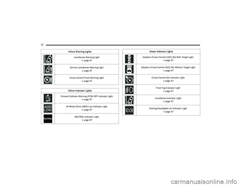
12 LaneSense Warning Light Úpage 97
Service LaneSense Warning Light Úpage 97
Cruise Control Fault Warning Light Úpage 97
Yellow Indicator Lights
Forward Collision Warning (FCW) OFF Indicator Light
Úpage 97
All Wheel Drive (AWD) Low Indicator Light Úpage 97
NEUTRAL Indicator Light Úpage 97
Yellow Warning LightsGreen Indicator Lights
Adaptive Cruise Control (ACC) Set With Target Light
Úpage 97
Adaptive Cruise Control (ACC) Set Without Target Light Úpage 97
Cruise Control Set Indicator Light Úpage 97
Front Fog Indicator Light Úpage 97
LaneSense Indicator Light Úpage 97
Parking/Headlights On Indicator Light Úpage 97
21_WD_OM_EN_USC_t.book Page 12
Page 21 of 340
GETTING TO KNOW YOUR VEHICLE19
HOW TO USE REMOTE START
Push and release the Remote Start button on the
key fob twice within five seconds. The vehicle
doors will lock, the parking lights will flash, and the
horn will chirp twice (if programmed). Then, the
engine will start, and the vehicle will remain in the
Remote Start mode for a 15 minute cycle. Pushing
the Remote Start button a third time shuts the
engine off.
To drive the vehicle, push the unlock button, and
with a valid Keyless Enter ‘n Go™ key fob in the
vehicle, place the ignition in the ON/RUN position.
NOTE:
With Remote Start, the engine will only run for
15 minutes.
Remote Start can only be used twice.
If an engine fault is present or fuel level is
low, the vehicle will start and then shut down in
10 seconds.
The park lamps will turn on and remain on
during Remote Start mode.
For security, power window operation is
disabled when the vehicle is in the Remote Start
mode.
The ignition must be placed in the ON/RUN posi -
tion before the Remote Start sequence can be
repeated for a third cycle. All of the following conditions must be met before
the engine will remote start:
Gear selector in PARK
Doors closed
Hood closed
Liftgate closed
Hazard switch off
Brake switch inactive (brake pedal not pressed)
Battery at an acceptable charge level
PANIC button not pushed
System not disabled from previous remote start
event
Vehicle Security system indicator flashing
Ignition in OFF position
Fuel level meets minimum requirement
Vehicle Security system is not signaling an
intrusion
Malfunction Indicator Light (MIL) is not
illuminated
TO EXIT REMOTE START MODE
To drive the vehicle after starting the Remote Start
system, either push and release the unlock button
on the key fob to unlock the doors, or unlock the
vehicle using Keyless Enter ‘n Go™ — Passive Entry
via the door handles, and disarm the Vehicle
Security system (if equipped). Then, prior to the
end of the 15 minute cycle, push and release the
START/STOP ignition button.
WARNING!
Do not start or run an engine in a closed
garage or confined area. Exhaust gas contains
Carbon Monoxide (CO) which is odorless and
colorless. Carbon Monoxide is poisonous and
can cause serious injury or death when
inhaled.
Keep key fobs away from children. Operation
of the Remote Start system, windows, door
locks or other controls could cause serious
injury or death.
2
21_WD_OM_EN_USC_t.book Page 19
Page 45 of 340
GETTING TO KNOW YOUR VEHICLE43
Automatic Dimming Mirror — If Equipped
The rearview mirror can be adjusted up, down, left,
and right. The mirror should be adjusted to center
on the view through the rear window.
This mirror automatically adjusts for headlight
glare from vehicles behind you.
NOTE:The Automatic Dimming Mirror feature is disabled
when the vehicle is in REVERSE to improve rear
view viewing.
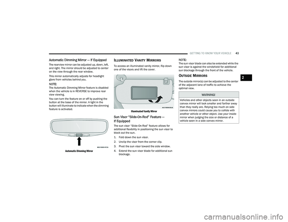
You can turn the feature on or off by pushing the
button at the base of the mirror. A light in the
button will illuminate to indicate when the dimming
feature is activated.
Automatic Dimming Mirror
ILLUMINATED VANITY MIRRORS
To access an illuminated vanity mirror, flip down
one of the visors and lift the cover.
Illuminated Vanity Mirror
Sun Visor “Slide-On-Rod” Feature —
If Equipped
The sun visor “Slide-On-Rod” feature allows for
additional flexibility in positioning the sun visor to
block out the sun.
1. Fold down the sun visor.
2. Unclip the visor from the corner clip.
3. Pivot the sun visor toward the side window.
4. Extend the sun visor blade for additional sun blockage.
NOTE:The sun visor blade can also be extended while the
sun visor is against the windshield for additional
sun blockage through the front of the vehicle.
OUTSIDE MIRRORS
The outside mirror(s) can be adjusted to the center
of the adjacent lane of traffic to achieve the
optimal view.
WARNING!
Vehicles and other objects seen in an outside
convex mirror will look smaller and farther away
than they really are. Relying too much on side
convex mirrors could cause you to collide with
another vehicle or other object. Use your inside
mirror when judging the size or distance of a
vehicle seen in a side convex mirror.
2
21_WD_OM_EN_USC_t.book Page 43
Page 49 of 340
GETTING TO KNOW YOUR VEHICLE47
PROGRAMMING HOMELINK® TO A
M
ISCELLANEOUS DEVICE
Refer to “Programming HomeLink® To A Garage
Door Opener” for the procedure on how to program
HomeLink® to a miscellaneous device, as it
follows the same procedure. Be sure to determine
if the device has a rolling code, or non-rolling code
before beginning the programming process.
NOTE:Canadian Radio Frequency (RF) laws require trans -
mitter signals to time-out (or quit) after several
seconds of transmission, which may not be long
enough for HomeLink® to pick up the signal during
programming. Similar to this Canadian law, some
U.S. gate operators are designed to time-out in the
same manner. The procedure may need to be
performed multiple times to successfully pair the
device to your HomeLink® buttons.
REPROGRAMMING A SINGLE
H
OMELINK® BUTTON
To reprogram a single HomeLink® button that has
been previously trained, without erasing all the
channels, follow the procedure below. Be sure to
determine whether the new device you want to
program the HomeLink® button to has a rolling
code, or non-rolling code.
1. Place the ignition to the ON/RUN position,
without starting the engine.
2. Push and hold the desired HomeLink® button until the HomeLink® indicator light begins to
flash after 20 seconds. Do not release the
button.
3. Without releasing the button , proceed with
Step 2 in “Programming HomeLink® To A
Garage Door Opener” and follow all remaining
steps.
CANADIAN/GATE OPERATOR
P
ROGRAMMING
For programming transmitters in Canada/United
States that require the transmitter signals to
“time-out” after several seconds of transmission:
Canadian Radio Frequency (RF) laws require
transmitter signals to time-out (or quit) after
several seconds of transmission, which may not be
long enough for HomeLink® to pick up the signal
during programming. Similar to this Canadian law,
some U.S. gate operators are designed to time-out
in the same manner.
It may be helpful to unplug the device during the
cycling process to prevent possible overheating of
the garage door or gate motor.
1. Place the ignition in the ON/RUN position.
NOTE:For vehicles equipped with Keyless Enter ‘n Go™,
place the ignition in the RUN position with the
engine on. Make sure while programming
HomeLink® with the engine on that your vehicle is
outside of your garage, or that the garage door
remains open at all times.
WARNING!
Your motorized door or gate will open and
close while you are programming the universal
transceiver. Do not program the transceiver if
people or pets are in the path of the door or
gate.
Do not run your vehicle in a closed garage or
confined area while programming the trans -
ceiver. Exhaust gas from your vehicle contains
Carbon Monoxide (CO) which is odorless and
colorless. Carbon Monoxide is poisonous
when inhaled and can cause you and others to
be severely injured or killed.
2
21_WD_OM_EN_USC_t.book Page 47
Page 51 of 340

GETTING TO KNOW YOUR VEHICLE49
Headlight Switch (Vehicles Sold In Canada)
NOTE:Vehicles sold in Canada are equipped with a head -
light switch without the OFF position. In order to
turn the exterior lights off, the headlight switch
must be rotated to AUTO position.
To turn on the headlights, rotate the headlight
switch clockwise. When the headlight switch is on,
the parking lights, taillights, license plate light and
instrument panel lights are also turned on. To turn
off the headlights, rotate the headlight switch back
to the O (off) position.
NOTE:For vehicles sold in Canada, rotate the headlight
switch clockwise from the parking lights and
instrument panel lights position to the first detent
to turn on headlights, parking lights, and
instrument panel lights. Rotate the headlight
switch to the second detent for the AUTO position.
NOTE:
Your vehicle is equipped with plastic headlight
and fog light (if equipped) lenses that are lighter
and less susceptible to stone breakage than
glass lights. Plastic is not as scratch resistant as
glass and therefore different lens cleaning
procedures must be followed.
To minimize the possibility of scratching the
lenses and reducing light output, avoid wiping
with a dry cloth. To remove road dirt, wash with
a mild soap solution followed by rinsing.
DAYTIME RUNNING LIGHTS (DRLS)
The Daytime Running Lights (DRLs) come on
whenever the engine is running. The lights will
remain on until the ignition is placed in the OFF
position, or the parking brake is engaged. The
headlight switch must be used during normal
nighttime driving.
NOTE:
For vehicles sold in Canada, the Daytime
Running Lights will automatically deactivate
when the front fog lights are turned on.
If allowed by law in the country in which the
vehicle was purchased, the Daytime Running
Lights can be turned on and off using the Ucon -
nect system Ú page 159.
On some vehicles, the Daytime Running Lights
may deactivate or reduce intensity on one side
of the vehicle (when a turn signal is activated on
that side), or on both sides of the vehicle (when
the hazard warning lights are activated).
HIGH/LOW BEAM SWITCH
Push the multifunction lever toward the instrument
panel to switch the headlights to high beams.
Pulling the multifunction back will turn the low
beams on.
1 — Rotate Headlight Switch
2 — Dimmer Control
3 — Fog Light Switch
CAUTION!
Do not use abrasive cleaning components,
solvents, steel wool or other abrasive materials
to clean the lenses.
2
21_WD_OM_EN_USC_t.book Page 49
Page 72 of 340
70GETTING TO KNOW YOUR VEHICLE
(Continued)
POWER INVERTER — IF EQUIPPED
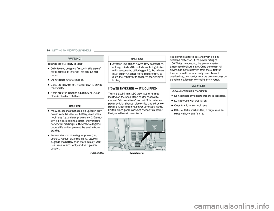
There is a 115 Volt, 150 Watt inverter outlet
located on the back of the center console to
convert DC current to AC current. This outlet can
power cellular phones, electronics and other low
power devices requiring power up to 150 Watts.
Certain video game consoles exceed this power
limit, as will most power tools.
Power Inverter
The power inverter is designed with built-in
overload protection. If the power rating of
150 Watts is exceeded, the power inverter
automatically shuts down. Once the electrical
device has been removed from the outlet the
inverter should automatically reset. To avoid
overloading the circuit, check the power ratings on
electrical devices prior to using the inverter.
WARNING!
To avoid serious injury or death:
Only devices designed for use in this type of
outlet should be inserted into any 12 Volt
outlet.
Do not touch with wet hands.
Close the lid when not in use and while driving
the vehicle.
If this outlet is mishandled, it may cause an
electric shock and failure.
CAUTION!
Many accessories that can be plugged in draw
power from the vehicle's battery, even when
not in use (i.e., cellular phones, etc.). Eventu
-
ally, if plugged in long enough, the vehicle's
battery will discharge sufficiently to degrade
battery life and/or prevent the engine from
starting.
Accessories that draw higher power (i.e.,
coolers, vacuum cleaners, lights, etc.) will
degrade the battery even more quickly. Only
use these intermittently and with greater
caution.
After the use of high power draw accessories,
or long periods of the vehicle not being started
(with accessories still plugged in), the vehicle
must be driven a sufficient length of time to
allow the generator to recharge the vehicle's
battery.
CAUTION!
WARNING!
To avoid serious injury or death:
Do not insert any objects into the receptacles.
Do not touch with wet hands.
Close the lid when not in use.
If this outlet is mishandled, it may cause an
electric shock and failure.
21_WD_OM_EN_USC_t.book Page 70
Page 74 of 340
72GETTING TO KNOW YOUR VEHICLE
Automatic Window Features
Auto-Down Feature
Both the driver and front passenger window
switches have an Auto-Down feature. Push the
window switch past the first detent, release, and
the window will go down automatically.
To cancel the Auto-Down movement, operate the
switch in either the up or down direction and
release the switch.
Auto-Up Feature With Anti-Pinch Protection —
Driver And Front Passenger Door Only
Lift the window switch fully upward to the second
detent, release, and the window will go up
automatically. To stop the window from going all the way up
during the Auto-Up operation, push down on the
switch briefly.
If the window runs into any obstacle during
Auto-Up, it will reverse direction and then go back
down. Remove the obstacle and use the window
switch again to close the window.
NOTE:Any impact due to rough road conditions may
trigger the auto reverse function unexpectedly
during Auto-Up. If this happens, pull the switch
lightly to the first detent and hold it to close the
window manually.
Reset Auto-Up
Should the Auto-Up feature stop working, the
window may need to be reset. To reset Auto-Up:
1. Make sure the door is fully closed.
2. Pull the window switch up to close the window
completely and continue to hold the switch up
for an additional two seconds after the window
is closed. 3. Push the window switch down firmly to the
second detent to open the window completely
and continue to hold the switch down for an
additional two seconds after the window is
fully open.
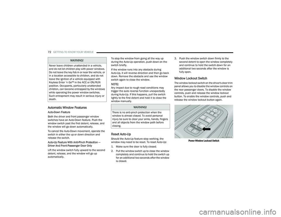
Window Lockout Switch
The window lockout switch on the driver's door trim
panel allows you to disable the window controls on
the rear passenger doors. To disable the window
controls, push and release the window lockout
button. To enable the window controls, push and
release the window lockout button again.
Power Window Lockout Switch
WARNING!
Never leave children unattended in a vehicle,
and do not let children play with power windows.
Do not leave the key fob in or near the vehicle, or
in a location accessible to children, and do not
leave the ignition of a vehicle equipped with
Keyless Enter ‘n Go™ in the ACC or ON/RUN
position. Occupants, particularly unattended
children, can become entrapped by the windows
while operating the power window switches.
Such entrapment may result in serious injury or
death.
WARNING!
There is no anti-pinch protection when the
window is almost closed. To avoid personal
injury be sure to clear your arms, hands, fingers
and all objects from the window path before
closing.
21_WD_OM_EN_USC_t.book Page 72