wiring DODGE DURANGO 2021 Owners Manual
[x] Cancel search | Manufacturer: DODGE, Model Year: 2021, Model line: DURANGO, Model: DODGE DURANGO 2021Pages: 340, PDF Size: 20.38 MB
Page 151 of 340
STARTING AND OPERATING149
Integrated Trailer Brake Module (ITBM) —
If Equipped
Your vehicle may have an ITBM for electric and
Electric Over Hydraulic (EOH) trailer brakes.
NOTE:This module has been designed and verified with
electric trailer brakes and EOH systems. Some
previous EOH systems may not be compatible
with ITBM.
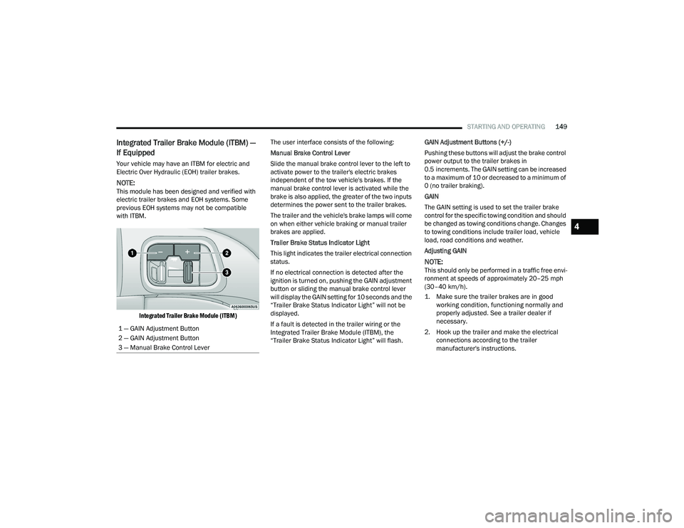
Integrated Trailer Brake Module (ITBM)
The user interface consists of the following:
Manual Brake Control Lever
Slide the manual brake control lever to the left to
activate power to the trailer's electric brakes
independent of the tow vehicle's brakes. If the
manual brake control lever is activated while the
brake is also applied, the greater of the two inputs
determines the power sent to the trailer brakes.
The trailer and the vehicle's brake lamps will come
on when either vehicle braking or manual trailer
brakes are applied.
Trailer Brake Status Indicator Light
This light indicates the trailer electrical connection
status.
If no electrical connection is detected after the
ignition is turned on, pushing the GAIN adjustment
button or sliding the manual brake control lever
will display the GAIN setting for 10 seconds and the
“Trailer Brake Status Indicator Light” will not be
displayed.
If a fault is detected in the trailer wiring or the
Integrated Trailer Brake Module (ITBM), the
“Trailer Brake Status Indicator Light” will flash. GAIN Adjustment Buttons (+/-)
Pushing these buttons will adjust the brake control
power output to the trailer brakes in
0.5 increments. The GAIN setting can be increased
to a maximum of 10 or decreased to a minimum of
0 (no trailer braking).
GAIN
The GAIN setting is used to set the trailer brake
control for the specific towing condition and should
be changed as towing conditions change. Changes
to towing conditions include trailer load, vehicle
load, road conditions and weather.
Adjusting GAIN
NOTE:This should only be performed in a traffic free envi
-
ronment at speeds of approximately 20–25 mph
(30–40 km/h).
1. Make sure the trailer brakes are in good working condition, functioning normally and
properly adjusted. See a trailer dealer if
necessary.
2. Hook up the trailer and make the electrical connections according to the trailer
manufacturer's instructions.
1 — GAIN Adjustment Button
2 — GAIN Adjustment Button
3 — Manual Brake Control Lever
4
21_WD_OM_EN_USC_t.book Page 149
Page 153 of 340
STARTING AND OPERATING151
Towing Requirements — Trailer Lights And
Wiring
Whenever pulling a trailer, regardless of the trailer
size, stop lights and turn signals on the trailer are
required for motoring safety.
The Trailer Tow Package may include a four- and
seven-pin wiring harness. Use a factory approved
trailer harness and connector.
NOTE:Do not cut or splice wiring into the vehicle’s wiring
harness.
The electrical connections are all complete to the
vehicle but you must mate the harness to a trailer
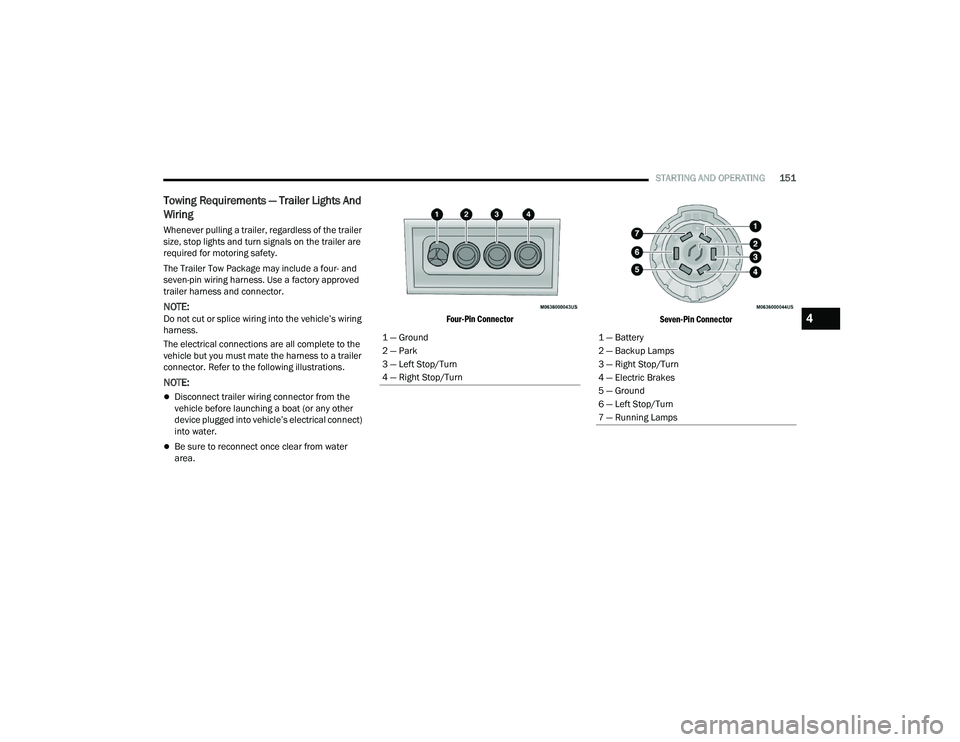
connector. Refer to the following illustrations.
NOTE:
Disconnect trailer wiring connector from the
vehicle before launching a boat (or any other
device plugged into vehicle’s electrical connect)
into water.
Be sure to reconnect once clear from water
area.
Four-Pin Connector
Seven-Pin Connector
1 — Ground
2 — Park
3 — Left Stop/Turn
4 — Right Stop/Turn
1 — Battery
2 — Backup Lamps
3 — Right Stop/Turn
4 — Electric Brakes
5 — Ground
6 — Left Stop/Turn
7 — Running Lamps
4
21_WD_OM_EN_USC_t.book Page 151
Page 213 of 340
SAFETY211
How To Disengage The Automatic Locking Mode
Unbuckle the combination lap/shoulder belt and
allow it to retract completely to disengage the
Automatic Locking Mode and activate the vehicle
sensitive (emergency) locking mode.
SUPPLEMENTAL RESTRAINT SYSTEMS
(SRS)
Some of the safety features described in this
section may be standard equipment on some
models, or may be optional equipment on others.
If you are not sure, ask an authorized dealer. The air bag system must be ready to protect you in
a collision. The Occupant Restraint Controller
(ORC) monitors the internal circuits and
interconnecting wiring associated with the
electrical Air Bag System Components.
Your vehicle may be equipped with the following
Air Bag System Components:
Air Bag System Components
Occupant Restraint Controller (ORC)
Air Bag Warning Light
Steering Wheel and Column
Instrument Panel
Knee Impact Bolsters
Driver and Front Passenger Air Bags
Seat Belt Buckle Switch
Supplemental Side Air Bags
Supplemental Knee Air Bags
Front and Side Impact Sensors
Seat Belt Pretensioners
Seat Track Position Sensors
Occupant Classification System
Air Bag Warning Light
The Occupant Restraint Controller (ORC)
monitors the readiness of the electronic
parts of the air bag system whenever the
ignition switch is in the START or ON/RUN
position. If the ignition switch is in the OFF position
or in the ACC position, the air bag system is not on
and the air bags will not inflate.
The ORC contains a backup power supply system
that may deploy the air bag system even if the
battery loses power or it becomes disconnected
prior to deployment.
The ORC turns on the Air Bag Warning Light in the
instrument panel for approximately four to eight
seconds for a self-check when the ignition switch is
first in the ON/RUN position. After the self-check,
the Air Bag Warning Light will turn off. If the ORC
detects a malfunction in any part of the system, it
turns on the Air Bag Warning Light, either
momentarily or continuously. A single chime will
sound to alert you if the light comes on again after
initial startup.
The ORC also includes diagnostics that will
illuminate the instrument panel Air Bag Warning
Light if a malfunction is detected that could affect
the air bag system. The diagnostics also record the
nature of the malfunction. While the air bag system
WARNING!
The seat belt assembly must be replaced if the
switchable Automatic Locking Retractor (ALR)
feature or any other seat belt function is not
working properly when checked according to
the procedures in the Service Manual.
Failure to replace the seat belt assembly
could increase the risk of injury in collisions.
Do not use the Automatic Locking Mode to
restrain occupants who are wearing the seat
belt or children who are using booster seats.
The locked mode is only used to install
rear-facing or forward-facing child restraints
that have a harness for restraining the child.6
21_WD_OM_EN_USC_t.book Page 211
Page 222 of 340
220SAFETY
The Side Air Bags will not deploy in all side
collisions, including some collisions at certain
angles, or some side collisions that do not impact
the area of the passenger compartment. The Side
Air Bags may deploy during angled or offset frontal
collisions where the front air bags deploy.
Side Air Bags are a supplement to the seat belt
restraint system. Side Air Bags deploy in less time
than it takes to blink your eyes.
NOTE:Air bag covers may not be obvious in the interior
trim, but they will open during air bag deployment.
Rollover Events
Side Air Bags and seat belt pretensioners are
designed to activate in certain rollover events. The
Occupant Restraint Controller (ORC) determines
whether deployment in a particular rollover event
is appropriate, based on the severity and type of
collision. Vehicle damage by itself is not a good
indicator of whether or not Side Air Bags and seat
belt pretensioners should have deployed. The Side Air Bags and seat belt pretensioners will
not deploy in all rollover events. The rollover
sensing system determines if a rollover event may
be in progress and whether deployment is
appropriate. In the event the vehicle experiences a
rollover or near rollover event, and deployment is
appropriate, the rollover sensing system will deploy
the side air bags and seat belt pretensioners on
both sides of the vehicle.
The SABICs may help reduce the risk of partial or
complete ejection of vehicle occupants through
side windows in certain rollover or side impact
events.
Air Bag System Components
NOTE:The Occupant Restraint Controller (ORC) monitors
the internal circuits and interconnecting wiring
associated with electrical Air Bag System Compo
-
nents listed below:
Occupant Restraint Controller (ORC)
Air Bag Warning Light
Steering Wheel and Column
Instrument Panel
Knee Impact Bolsters
Driver and Front Passenger Air Bags
Seat Belt Buckle Switch
Supplemental Side Air Bags
WARNING!
Occupants, including children, who are up
against or very close to Side Air Bags can be
seriously injured or killed. Occupants,
including children, should never lean on or
sleep against the door, side windows, or area
where the side air bags inflate, even if they are
in an infant or child restraint.
Seat belts (and child restraints where appro -
priate) are necessary for your protection in all
collisions. They also help keep you in position,
away from an inflating Side Air Bag. To get the
best protection from the Side Air Bags, occu -
pants must wear their seat belts properly and
sit upright with their backs against the seats.
Children must be properly restrained in a child
restraint or booster seat that is appropriate for
the size of the child.
WARNING!
Side Air Bags need room to inflate. Do not lean
against the door or window. Sit upright in the
center of the seat.
Being too close to the Side Air Bags during
deployment could cause you to be severely
injured or killed.
Relying on the Side Air Bags alone could lead
to more severe injuries in a collision. The Side
Air Bags work with your seat belt to restrain
you properly. In some collisions, Side Air Bags
won’t deploy at all. Always wear your seat belt
even though you have Side Air Bags.
21_WD_OM_EN_USC_t.book Page 220
Page 224 of 340
222SAFETY
(Continued)
Cut off battery power to the:
Engine
Electric Motor (if equipped)
Electric power steering
Brake booster
Electric park brake
Automatic transmission gear selector
Horn
Front wiper
Headlamp washer pump
NOTE:After an accident, remember to cycle the ignition to
the STOP (OFF/LOCK) position and remove the key
from the ignition switch to avoid draining the
battery. Carefully check the vehicle for fuel leaks in
the engine compartment and on the ground near
the engine compartment and fuel tank before
resetting the system and starting the engine. If
there are no fuel leaks or damage to the vehicle
electrical devices (e.g. headlights) after an
accident, reset the system by following the
procedure described below. If you have any doubt,
contact an authorized dealer.
Enhanced Accident Response System
Reset Procedure
In order to reset the Enhanced Accident Response
System functions after an event, the ignition switch
must be changed from ignition START or ON/RUN
to ignition OFF. Carefully check the vehicle for fuel
leaks in the engine compartment and on the
ground near the engine compartment and fuel
tank before resetting the system and starting the
engine.
After an accident, if the vehicle will not start after
performing the reset procedure, the vehicle must
be towed to an authorized dealer to be inspected
and to have the Enhanced Accident Response
System reset.
Maintaining Your Air Bag System Event Data Recorder (EDR)
This vehicle is equipped with an event data
recorder (EDR). The main purpose of an EDR is to
record, in certain crash or near crash-like
situations, such as an air bag deployment or hitting
a road obstacle, data that will assist in
understanding how a vehicle’s systems performed.
The EDR is designed to record data related to
WARNING!
Modifications to any part of the air bag system
could cause it to fail when you need it. You
could be injured if the air bag system is not
there to protect you. Do not modify the compo-
nents or wiring, including adding any kind of
badges or stickers to the steering wheel hub
trim cover or the upper passenger side of the
instrument panel. Do not modify the front
fascia/bumper, vehicle body structure, or add
aftermarket side steps or running boards.
It is dangerous to try to repair any part of the
air bag system yourself. Be sure to tell anyone
who works on your vehicle that it has an air
bag system.
Do not attempt to modify any part of your air
bag system. The air bag may inflate acciden -
tally or may not function properly if modifica -
tions are made. Take your vehicle to an
authorized dealer for any air bag system
service. If your seat, including your trim cover
and cushion, needs to be serviced in any way
(including removal or loosening/tightening of
seat attachment bolts), take the vehicle to an
authorized dealer. Only manufacturer
approved seat accessories may be used. If it is
necessary to modify the air bag system for
persons with disabilities, contact an autho -
rized dealer.
WARNING!
21_WD_OM_EN_USC_t.book Page 222
Page 338 of 340
336 Rotation
.................................................... 312Safety.............................................. 295, 303Sizes.......................................................... 296Snow Tires................................................. 307Spare Tires............................. 249, 307, 308Spinning.................................................... 305Trailer Towing............................................ 148Tread Wear Indicators............................... 305Wheel Nut Torque..................................... 317To Open Hood.................................................. 74Tongue Weight/Trailer Weight....................... 147Tow N Go....................................................... 115Towing................................................. 142, 261Disabled Vehicle........................................ 261Guide......................................................... 145Recreational.............................................. 153Weight....................................................... 145Towing Behind A Motorhome......................... 153Traction Control............................................. 194Trailer Sway Control (TSC)............................. 195Trailer Towing................................................ 142Hitches...................................................... 145Minimum Requirements............................ 147Tips........................................................... 152Trailer And Tongue Weight........................ 147Wiring........................................................ 151Trailer Towing Guide...................................... 145Trailer Weight................................................ 145Transfer Case................................................ 285Electronically Shifted................................. 112
Fluid......................................................... 323Maintenance............................................ 285Transmission................................................ 108Automatic........................................ 108, 284Fluid......................................................... 323Maintenance............................................ 284Shifting..................................................... 106Transporting Pets.......................................... 239Tread Wear Indicators.................................. 305Turn Signals............................................98, 294
U
Uconnect SettingsCustomer Programmable Features
...... 23, 26Passive Entry Programming.................. 23, 26Uniform Tire Quality Grades.......................... 312Unleaded Gasoline....................................... 318Untwisting Procedure, Seat Belt................... 208
V
Vanity Mirrors.................................................. 43Vehicle Identification Number (VIN).............. 317Vehicle Loading................................... 141, 301Vehicle Maintenance.................................... 271Vehicle Modifications/Alterations.................... 10Vehicle Security System................................... 21Vehicle Storage.......................................63, 313Voice Command............................................... 41Voice Recognition System (VR)........................ 41
W
Warning Flashers, Hazard............................. 243Warning lightRed..............................................................91Yellow..........................................................94Warning Lights
(Instrument Cluster Descriptions)....................95Warning Lights and Messages.........................91Warnings, Roll Over............................................ 9Warranty Information.................................... 326Washers, Windshield............................. 53, 270Washing Vehicle............................................ 314Wheel And Wheel Tire Care........................... 309Wheel And Wheel Tire Trim........................... 309Wind Buffeting.................................................73Window Fogging...............................................63Windows..........................................................71Power...........................................................71Reset Auto-Up..............................................72Windshield Defroster.................................... 240Windshield Washers.............................. 53, 270Fluid.......................................................... 270Windshield Wiper Blades.............................. 276Windshield Wipers...........................................53Wipers Blade Replacement........................... 276Wipers, Intermittent.........................................53Wipers, Rain Sensitive.....................................54Wireless Charging Pad.....................................71
21_WD_OM_EN_USC_t.book Page 336