console DODGE DURANGO 2022 User Guide
[x] Cancel search | Manufacturer: DODGE, Model Year: 2022, Model line: DURANGO, Model: DODGE DURANGO 2022Pages: 332, PDF Size: 19.82 MB
Page 69 of 332
GETTING TO KNOW YOUR VEHICLE67
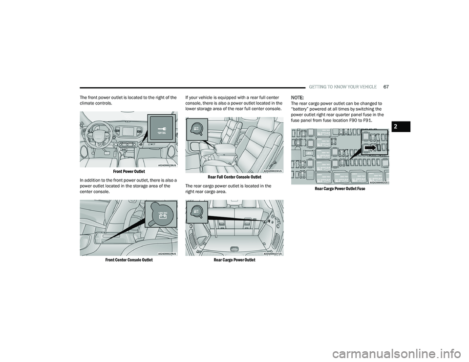
The front power outlet is located to the right of the
climate controls.
Front Power Outlet
In addition to the front power outlet, there is also a
power outlet located in the storage area of the
center console.
Front Center Console Outlet
If your vehicle is equipped with a rear full center
console, there is also a power outlet located in the
lower storage area of the rear full center console.
Rear Full Center Console Outlet
The rear cargo power outlet is located in the
right rear cargo area.
Rear Cargo Power Outlet
NOTE:The rear cargo power outlet can be changed to
“battery” powered at all times by switching the
power outlet right rear quarter panel fuse in the
fuse panel from fuse location F90 to F91.
Rear Cargo Power Outlet Fuse
2
22_WD_OM_EN_USC_t.book Page 67
Page 70 of 332
68GETTING TO KNOW YOUR VEHICLE
(Continued)
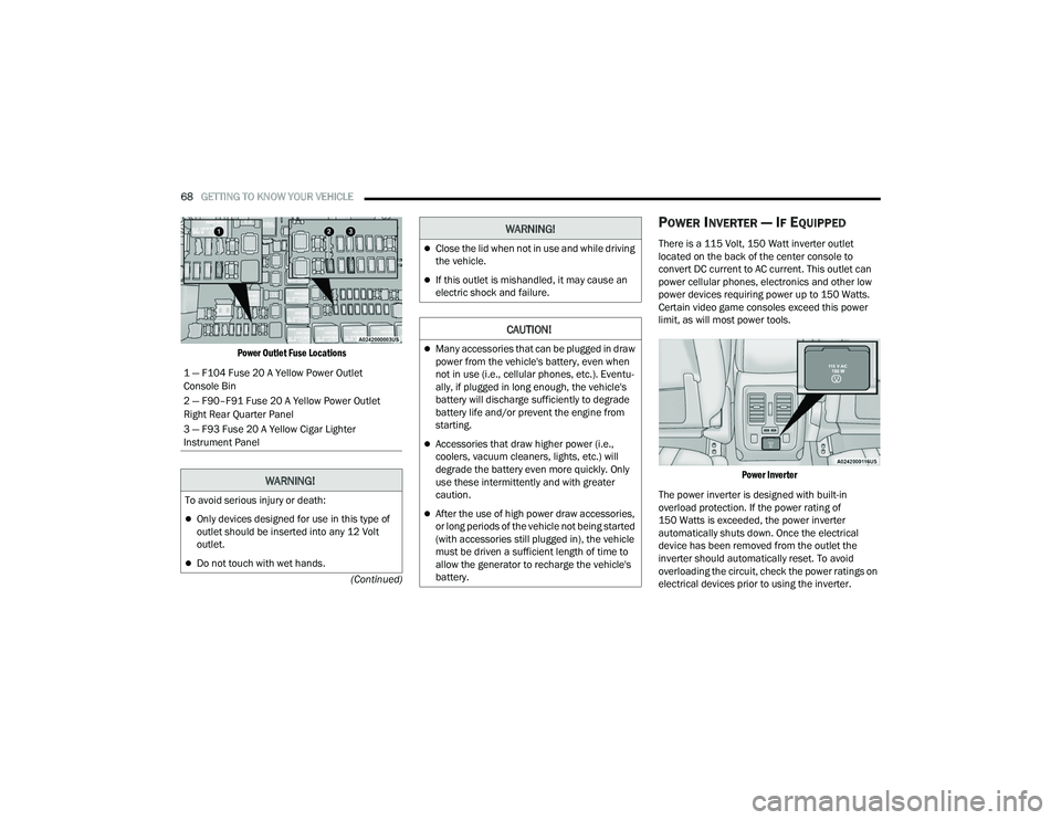
Power Outlet Fuse Locations
POWER INVERTER — IF EQUIPPED
There is a 115 Volt, 150 Watt inverter outlet
located on the back of the center console to
convert DC current to AC current. This outlet can
power cellular phones, electronics and other low
power devices requiring power up to 150 Watts.
Certain video game consoles exceed this power
limit, as will most power tools.
Power Inverter
The power inverter is designed with built-in
overload protection. If the power rating of
150 Watts is exceeded, the power inverter
automatically shuts down. Once the electrical
device has been removed from the outlet the
inverter should automatically reset. To avoid
overloading the circuit, check the power ratings on
electrical devices prior to using the inverter.
1 — F104 Fuse 20 A Yellow Power Outlet
Console Bin
2 — F90–F91 Fuse 20 A Yellow Power Outlet
Right Rear Quarter Panel
3 — F93 Fuse 20 A Yellow Cigar Lighter
Instrument Panel
WARNING!
To avoid serious injury or death:
Only devices designed for use in this type of
outlet should be inserted into any 12 Volt
outlet.
Do not touch with wet hands.
Close the lid when not in use and while driving
the vehicle.
If this outlet is mishandled, it may cause an
electric shock and failure.
CAUTION!
Many accessories that can be plugged in draw
power from the vehicle's battery, even when
not in use (i.e., cellular phones, etc.). Eventu
-
ally, if plugged in long enough, the vehicle's
battery will discharge sufficiently to degrade
battery life and/or prevent the engine from
starting.
Accessories that draw higher power (i.e.,
coolers, vacuum cleaners, lights, etc.) will
degrade the battery even more quickly. Only
use these intermittently and with greater
caution.
After the use of high power draw accessories,
or long periods of the vehicle not being started
(with accessories still plugged in), the vehicle
must be driven a sufficient length of time to
allow the generator to recharge the vehicle's
battery.
WARNING!
22_WD_OM_EN_USC_t.book Page 68
Page 73 of 332
GETTING TO KNOW YOUR VEHICLE71
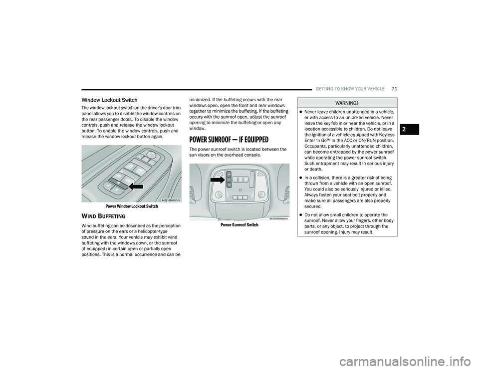
Window Lockout Switch
The window lockout switch on the driver's door trim
panel allows you to disable the window controls on
the rear passenger doors. To disable the window
controls, push and release the window lockout
button. To enable the window controls, push and
release the window lockout button again.
Power Window Lockout Switch
WIND BUFFETING
Wind buffeting can be described as the perception
of pressure on the ears or a helicopter-type
sound in the ears. Your vehicle may exhibit wind
buffeting with the windows down, or the sunroof
(if equipped) in certain open or partially open
positions. This is a normal occurrence and can be minimized. If the buffeting occurs with the rear
windows open, open the front and rear windows
together to minimize the buffeting. If the buffeting
occurs with the sunroof open, adjust the sunroof
opening to minimize the buffeting or open any
window.
POWER SUNROOF — IF EQUIPPED
The power sunroof switch is located between the
sun visors on the overhead console.
Power Sunroof Switch
WARNING!
Never leave children unattended in a vehicle,
or with access to an unlocked vehicle. Never
leave the key fob in or near the vehicle, or in a
location accessible to children. Do not leave
the ignition of a vehicle equipped with Keyless
Enter ‘n Go™ in the ACC or ON/RUN position.
Occupants, particularly unattended children,
can become entrapped by the power sunroof
while operating the power sunroof switch.
Such entrapment may result in serious injury
or death.
In a collision, there is a greater risk of being
thrown from a vehicle with an open sunroof.
You could also be seriously injured or killed.
Always fasten your seat belt properly and
make sure all passengers are also properly
secured.
Do not allow small children to operate the
sunroof. Never allow your fingers, other body
parts, or any object, to project through the
sunroof opening. Injury may result.
2
22_WD_OM_EN_USC_t.book Page 71
Page 75 of 332
GETTING TO KNOW YOUR VEHICLE73
HOOD
OPENING THE HOOD
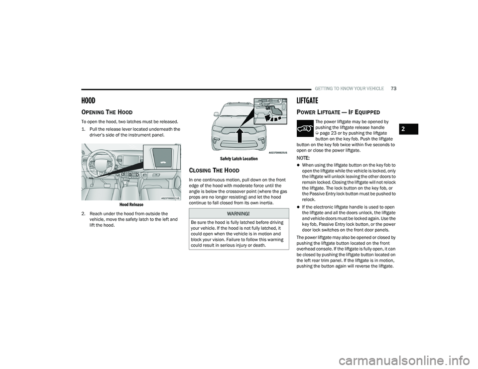
To open the hood, two latches must be released.
1. Pull the release lever located underneath the
driver’s side of the instrument panel.
Hood Release
2. Reach under the hood from outside the vehicle, move the safety latch to the left and
lift the hood.
Safety Latch Location
CLOSING THE HOOD
In one continuous motion, pull down on the front
edge of the hood with moderate force until the
angle is below the crossover point (where the gas
props are no longer resisting) and let the hood
continue to fall closed from its own inertia.
LIFTGATE
POWER LIFTGATE — IF EQUIPPED
The power liftgate may be opened by
pushing the liftgate release handle
Ú
page 23 or by pushing the liftgate
button on the key fob. Push the liftgate
button on the key fob twice within five seconds to
open or close the power liftgate.
NOTE:
When using the liftgate button on the key fob to
open the liftgate while the vehicle is locked, only
the liftgate will unlock leaving the other doors to
remain locked. Closing the liftgate will not relock
the liftgate. The lock button on the key fob, or
the Passive Entry lock button must be pushed to
relock.
If the electronic liftgate handle is used to open
the liftgate and all the doors unlock, the liftgate
and vehicle doors must be locked again. Use the
key fob, Passive Entry lock button, or the power
door lock switches on the front door panels.
The power liftgate may also be opened or closed by
pushing the liftgate button located on the front
overhead console. If the liftgate is fully open, it can
be closed by pushing the liftgate button located on
the left rear trim panel. If the liftgate is in motion,
pushing the button again will reverse the liftgate.
WARNING!
Be sure the hood is fully latched before driving
your vehicle. If the hood is not fully latched, it
could open when the vehicle is in motion and
block your vision. Failure to follow this warning
could result in serious injury or death.
2
22_WD_OM_EN_USC_t.book Page 73
Page 91 of 332
GETTING TO KNOW YOUR INSTRUMENT PANEL89
Unusual driving cycles (short trips separated by
long parking periods).
The vehicle was parked for an extended period
of time (weeks, months).
The battery was recently replaced and was not
charged completely.
The battery was discharged by an electrical load
left on when the vehicle was parked.
The battery was used for an extended period
with the engine not running to supply radio,
lights, chargers, +12 Volt portable appliances
like vacuum cleaners, game consoles and
similar devices.
What to do when an electrical load reduction
action message is present (“Battery Saver On” or
“Battery Saver Mode”)
During a trip:
Reduce power to unnecessary loads if possible:
Turn off redundant lights (interior or exterior)
Check what may be plugged in to power
outlets +12 Volt, 115 Volt AC, USB ports
Check HVAC settings (blower, temperature)
Check the audio settings (volume) After a trip:
Check if any aftermarket equipment was
installed (additional lights, upfitter electrical
accessories, audio systems, alarms) and review
specifications if any (load and Ignition Off Draw
currents).
Evaluate the latest driving cycles (distance,
driving time and parking time).
The vehicle should have service performed if
the message is still present during consecutive
trips, and if the evaluation and driving pattern of
the vehicle did not help to identify the cause.
WARNING LIGHTS AND MESSAGES
The warning/indicator lights will illuminate in the
instrument panel together with a dedicated
message and/or acoustic signal when applicable.
These indications are indicative and precautionary
and as such must not be considered as exhaustive
and/or alternative to the information contained in
the Owner’s Manual, which you are advised to
read carefully in all cases. Always refer to the
information in this chapter in the event of a failure
indication. All active telltales will display first if
applicable. The system check menu may appear
different based upon equipment options and
current vehicle status. Some telltales are optional
and may not appear.
RED WARNING LIGHTS
Seat Belt Reminder Warning Light
This warning light indicates when the
driver or passenger seat belt is
unbuckled. When the ignition is first
placed in the ON/RUN or ACC/ON/RUN
position and if the driver’s seat belt is unbuckled,
a chime will sound and the light will turn on. When
driving, if the driver or front passenger seat belt
remains unbuckled, the Seat Belt Reminder Light
will flash or remain on continuously and a chime
will sound Ú page 196.
Air Bag Warning Light
This warning light will illuminate to
indicate a fault with the air bag, and will
turn on for four to eight seconds as a bulb
check when the ignition is placed in the
ON/RUN or ACC/ON/RUN position. This light will
illuminate with a single chime when a fault with the
air bag has been detected, it will stay on until the
fault is cleared. If the light is either not on during
startup, stays on, or turns on while driving, have
the system inspected at an authorized dealer as
soon as possible.
3
22_WD_OM_EN_USC_t.book Page 89
Page 111 of 332
STARTING AND OPERATING109
AutoStick mode has the following operational
benefits:
The transmission will automatically downshift
as the vehicle slows (to prevent engine lugging)
and will display the current gear.
The transmission will automatically downshift to
FIRST gear when coming to a stop. After a stop,
the driver should manually upshift (+) the trans -
mission as the vehicle is accelerated.
You can start out, from a stop, in FIRST or
SECOND gear. Tapping (+) at a stop will allow
starting in SECOND gear. Starting out in
SECOND gear can be helpful in snowy or icy
conditions.
If a requested downshift would cause the
engine to over-speed, that shift will not occur.
The system will ignore attempts to upshift at too
low of a vehicle speed.
Holding the (-) paddle pressed, or holding the
gear selector in the (-) position, will downshift
the transmission to the lowest gear possible at
the current speed.
Transmission shifting will be more noticeable
when AutoStick is enabled.
The system may revert to automatic shift mode
if a fault or overheat condition is detected. To disengage AutoStick mode, return the gear
selector to the DRIVE (D) position, or press and
hold the (+) paddle shifter until "D" is indicated in
the instrument cluster. You can shift in or out of
AutoStick mode at any time without taking your
foot off the accelerator pedal.
SPORT MODE — IF EQUIPPED
Your vehicle is equipped with a SPORT Mode
feature. The engine, transmission, and steering
systems are all set to their SPORT settings. SPORT
Mode will provide improved throttle response and
modified transmission shift points for an enhanced
driving experience, as well as greater amount of
steering feel. This mode may be activated and
deactivated by pushing the SPORT button on the
instrument panel switch bank.
ALL-WHEEL DRIVE OPERATION
SINGLE-SPEED OPERATING
I
NSTRUCTIONS/PRECAUTIONS —
I
F EQUIPPED
This system contains a single-speed (HI range only)
transfer case, which provides convenient full-time
All-Wheel Drive (AWD). No driver interaction is
required. The Brake Traction Control (BTC) System,
which combines standard ABS and Traction
Control, provides resistance to any wheel that is
slipping to allow additional torque transfer to
wheels with traction.
NOTE:This system is not appropriate for conditions where
AWD LOW is recommended Ú page 153.
ELECTRONICALLY SHIFTED TRANSFER
C
ASE — IF EQUIPPED
This is an electronically shifted transfer case and it
is operated by the AWD control switch, which is
located on the center console.
WARNING!
Do not downshift for additional engine braking
on a slippery surface. The drive wheels could
lose their grip and the vehicle could skid,
causing a collision or personal injury.
4
22_WD_OM_EN_USC_t.book Page 109
Page 211 of 332
SAFETY209
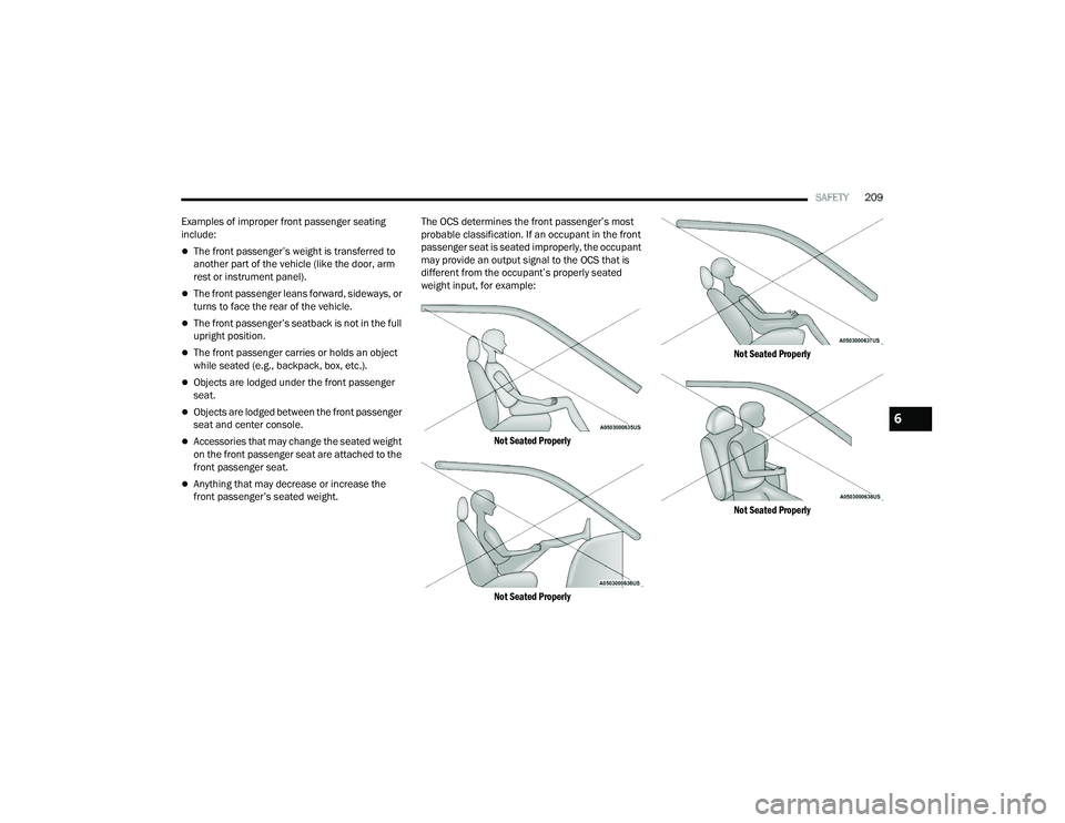
Examples of improper front passenger seating
include:
The front passenger’s weight is transferred to
another part of the vehicle (like the door, arm
rest or instrument panel).
The front passenger leans forward, sideways, or
turns to face the rear of the vehicle.
The front passenger’s seatback is not in the full
upright position.
The front passenger carries or holds an object
while seated (e.g., backpack, box, etc.).
Objects are lodged under the front passenger
seat.
Objects are lodged between the front passenger
seat and center console.
Accessories that may change the seated weight
on the front passenger seat are attached to the
front passenger seat.
Anything that may decrease or increase the
front passenger’s seated weight. The OCS determines the front passenger’s most
probable classification. If an occupant in the front
passenger seat is seated improperly, the occupant
may provide an output signal to the OCS that is
different from the occupant’s properly seated
weight input, for example:
Not Seated Properly
Not Seated Properly Not Seated Properly
Not Seated Properly
6
22_WD_OM_EN_USC_t.book Page 209
Page 252 of 332
250IN CASE OF EMERGENCY
In the event it is observed that the temperature
gauge is moving towards or close to the HOT (H)
position, you can reduce the potential for
overheating by taking the appropriate action.
On the highways — slow down.
In city traffic — while stopped, place the trans -
mission in NEUTRAL (N), but do not increase the
engine idle speed while preventing vehicle
motion with the brakes.
If your Air Conditioner (A/C) is on, turn it off. The
A/C system adds heat to the engine cooling
system and turning the A/C off can help remove
this heat.
You can also turn the temperature control to
maximum heat, the mode control to floor and
the blower control to high. This allows the heater
core to act as a supplement to the radiator and
aids in removing heat from the engine cooling
system.
MANUAL PARK RELEASE
In order to move the vehicle in cases where the
transmission will not shift out of PARK (P) (such as
a depleted battery), a Manual Park Release is
available. Follow these steps to use the Manual Park
Release:
1. Firmly apply the parking brake.
2. Open the center console and locate the
Manual Park Release cover, remove it by
snapping the cover away from the console
hinges.
Manual Park Release Cover
NOTE:Depending on your vehicle’s trim level, the Manual
Park Release cable may be located in a different
area on the center console.
3. Press and maintain firm pressure on the brake pedal.CAUTION!
Driving with a hot cooling system could damage
your vehicle. If the temperature gauge reads
HOT (H), pull over and stop the vehicle. Idle the
vehicle with the air conditioner turned off until
the pointer drops back into the normal range. If
the pointer remains on HOT (H), and you hear
continuous chimes, turn the engine off
immediately and call for service.
WARNING!
You or others can be badly burned by hot engine
coolant (antifreeze) or steam from your radiator.
If you see or hear steam coming from under the
hood, do not open the hood until the radiator
has had time to cool. Never try to open a cooling
system pressure cap when the radiator or
coolant bottle is hot.
WARNING!
Always secure your vehicle by fully applying the
parking brake before activating the Manual Park
Release. In addition, you should be seated in the
driver’s seat with your foot firmly on the brake
pedal when activating the Manual Park Release.
Activating the Manual Park Release will allow
your vehicle to roll away if it is not secured by the
parking brake, or by proper connection to a tow
vehicle. Activating the Manual Park Release on
an unsecured vehicle could lead to serious
injury or death for those in or around the vehicle.
22_WD_OM_EN_USC_t.book Page 250
Page 285 of 332
SERVICING AND MAINTENANCE283
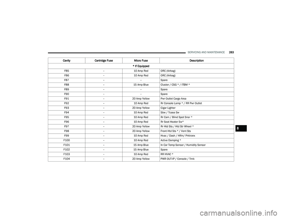
F85 –10 Amp Red ORC (Airbag)
F86 –10 Amp Red ORC (Airbag)
F87 ––Spare
F88 –15 Amp Blue Cluster / CSG * / ITBM *
F89 ––Spare
F90 ––Spare
F91 –20 Amp Yellow Pwr Outlet Cargo Area
F92 –10 Amp Red Rr Console Lamp * / RR Pwr Outlet
F93 –20 Amp Yellow Cigar Lighter
F94 –10 Amp Red Sbw / Tcase Sw
F95 –10 Amp Red Rr Cam / Blind Spot Snsr *
F96 –10 Amp Red Rr Seat Heater Sw*
F97 –20 Amp Yellow Rr Htd Sts / Htd Str Wheel *
F98 –20 Amp Yellow Front Htd Sts * / Vent Sts
F99 –10 Amp Red Hvac / Dash / Hlfm/ Prktronx
F100 –10 Amp Red Active Damping *
F101 –15 Amp Blue In Car Temp Sensor / Humidity Sensor
F102 –15 Amp Blue Spare
F103 –10 Amp Red RR HVAC *
F104 –20 Amp Yellow PWR OUT-IP / Console / Trnk
Cavity Cartridge Fuse Micro Fuse Description
* If Equipped
8
22_WD_OM_EN_USC_t.book Page 283
Page 286 of 332
284SERVICING AND MAINTENANCE
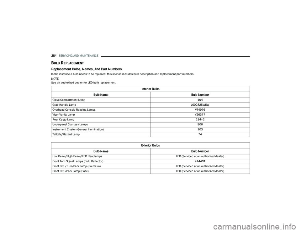
BULB REPLACEMENT
Replacement Bulbs, Names, And Part Numbers
In the instance a bulb needs to be replaced, this section includes bulb description and replacement part numbers.
NOTE:See an authorized dealer for LED bulb replacement.
Interior Bulbs
Bulb Name Bulb Number
Glove Compartment Lamp 194
Grab Handle Lamp L002825W5W
Overhead Console Reading Lamps VT4976
Visor Vanity Lamp V26377
Rear Cargo Lamp 214–2
Underpanel Courtesy Lamps 906
Instrument Cluster (General Illumination) 103
Telltale/Hazard Lamp 74
Exterior Bulbs
Bulb Name Bulb Number
Low Beam/High Beam/LED Headlamps LED (Serviced at an authorized dealer)
Front Turn Signal Lamps (Bulb Reflector) 7444NA
Front DRL/Turn/Park Lamp (Premium) LED (Serviced at an authorized dealer)
Front DRL/Park Lamp (Base) LED (Serviced at an authorized dealer)
22_WD_OM_EN_USC_t.book Page 284