remote start DODGE DURANGO 2022 User Guide
[x] Cancel search | Manufacturer: DODGE, Model Year: 2022, Model line: DURANGO, Model: DODGE DURANGO 2022Pages: 332, PDF Size: 19.82 MB
Page 39 of 332
GETTING TO KNOW YOUR VEHICLE37
Rear Heated Seats — If Equipped
The two second row outboard seats may
be equipped with heated seats. There
are two heated seat switches that allow
the rear passengers to operate the seats
independently. The heated seat switches for each
heater are located on the rear of the center
console.
You can choose from HI, LO, or off heat settings.
Amber indicator lights in each switch indicate the
level of heat in use. Two indicator lights will
illuminate for HI, one for LO and none for off.
Push the switch once to turn the HI setting on.
Push the switch a second time to turn the
LO setting on.
Push the switch a third time to turn the heating
elements off.
The level of heat selected will stay on until the
operator changes it.
NOTE:The engine must be running for the heated seats to
operate.
FRONT VENTILATED SEATS —
I
F EQUIPPED
The ventilated seats control buttons are
located on the center stack below the
radio screen, or within the Uconnect
system. The fans operate at three
speeds: HI, MED, and LO.
Push the ventilated seat switch once to
choose HI.
Push the ventilated seat switch a second time to
choose MED.
Push the ventilated seat switch a third time to
choose LO.
Push the ventilated seat switch a fourth time to
turn the ventilation off.
NOTE:The engine must be running for the ventilated
seats to operate.
For information on use with the Remote Start
system, see Ú page 20.
HEAD RESTRAINTS
Head restraints are designed to reduce the risk of
injury by restricting head movement in the event of
a rear impact. Head restraints should be adjusted
so that the top of the head restraint is located
above the top of your ear.
Front Head Restraints
Your vehicle is equipped with front four-way driver
and passenger head restraints.
To raise the head restraint, pull upward on the
head restraint. To lower the head restraint, push
the adjustment button, located at the base of the
head restraint, and push downward on the head
restraint.
WARNING!
All occupants, including the driver, should not
operate a vehicle or sit in a vehicle’s seat until
the head restraints are placed in their proper
positions in order to minimize the risk of neck
injury in the event of a crash.
Head restraints should never be adjusted
while the vehicle is in motion. Driving a vehicle
with the head restraints improperly adjusted
or removed could cause serious injury or
death in the event of a collision.
2
22_WD_OM_EN_USC_t.book Page 37
Page 85 of 332
GETTING TO KNOW YOUR INSTRUMENT PANEL83
The instrument cluster display is located in the
center portion of the cluster and consist of multiple
sections:
Main Screen — The inner ring of the display will
illuminate in gray under normal conditions,
yellow for non critical warnings, red for critical
warnings, and white for on demand information.
Submenu Dots — Whenever there are
submenus available, the position within the
submenus is shown here.
Reconfigurable Telltales/Information
Gear Selector Status (PRND)
Driver Interactive Display (Compass, Temp,
Range to Empty, Trip A, Trip B, Average Fuel
Economy, Current Fuel Economy, Time, Trailer
Trip and Gain)
All Wheel Drive (AWD) Status — If Equipped The instrument cluster display will normally display
the main menu or the screens of a selected feature
of the main menu. The main display area also
displays pop-up messages that consist possible
warning or information messages. These pop-up
messages fall into several categories:
Five Second Stored Messages
When the appropriate conditions occur, this
type of message takes control of the main
display area for five seconds and then returns to
the previous screen. Most of the messages of
this type are then stored (as long as the condi-
tion that activated it remains active) and can be
reviewed from the “Messages” main menu item.
Examples of this message type are “Right Front
Turn Signal Lamp Out” and “Low Tire Pressure.”
Unstored Messages
This message type is displayed indefinitely or
until the condition that activated the message is
cleared. Examples of this message type are
“Turn Signal On” (if a turn signal is left on) and
“Lights On” (if driver leaves the vehicle with the
lights on).
Unstored Messages Until RUN
These messages deal primarily with the Remote
Start feature. This message type is displayed
until the ignition is in the RUN state. Examples of
this message type are “Remote Start Canceled -
Door Ajar” and “Press Brake Pedal and Push
Button to Start.”
Five Second Unstored Messages
When the appropriate conditions occur, this
type of message takes control of the main
display area for five seconds and then returns to
the previous screen. An example of this
message type is “Automatic High Beams On.”
3
22_WD_OM_EN_USC_t.book Page 83
Page 87 of 332
GETTING TO KNOW YOUR INSTRUMENT PANEL85
DISPLAY AND MESSAGES
Includes the following, but not limited to:
The Reconfigurable Telltales section is divided into the white or yellow telltales area on the left, and the green or red telltales area on the right.Front Seat Belts Unbuckled
Driver Seat Belt UnbuckledPassenger Seat Belt Unbuckled
Traction Control Off Washer Fluid LowOil Pressure Low
Oil Change Due Fuel LowService Anti-lock Brake System
Service Electronic Throttle Control Service Power SteeringCruise Off
Cruise Ready ACC OverrideCruise Set To XXX mph or km/h
Service Shifter Tire Pressure Screen With Low Tire(s)Service Tire Pressure System
Park Brake Engaged Brake Fluid LowEngine Temperature Hot
Lights On Right Front Turn Signal Light OutRight Rear Turn Signal Light Out
Left Front Turn Signal Light Out Left Rear Turn Signal Light OutIgnition or Accessory On
Vehicle Not In Park Remote Start Active Push Start ButtonRemote Start Canceled Fuel Low
Remote Start Canceled Door Open Remote Start Canceled Hood OpenRemote Start Canceled Liftgate Open
Remote Start Canceled Time Expired Remote Start Disabled Start To ResetService Air Bag System
Service Air Bag Warning Light Door OpenLiftgate Open
Hood Open Shift Not AllowedVehicle Speed Too High To Shift to D
Vehicle Speed is Too High to Shift to R Vehicle Speed is Too High to Shift to PService Transmission
3
22_WD_OM_EN_USC_t.book Page 85
Page 164 of 332
162MULTIMEDIA
New Text Message Pop-Ups This setting will allow you to have pop-up notifications for new text messages.
This setting options are “On” and “Off”.
Missed Calls Message This setting will allow you to have pop-up notifications for missed calls.
This setting options are “On” and “Off”.
Personal Settings Linked to Key Fob This setting will recall preset radio stations and driver seat position that have
been linked to the key fob.
Navigation Pop-Ups This setting will allow you to have pop-up notifications for Navigation.
This setting options are “On” and “Off”.
Navigation Settings This setting will direct you to the Navigation settings within Navigation Mode.
Auto-On Driver Heated/Ventilated Seat & Heated Steering Wheel With Vehicle Start This setting will activate the vehicle’s comfort systems and heated seats or
heated steering wheel when the vehicle is remote started or ignition is
started. The “Off” setting will not activate the comfort systems. The “Remote
Start” setting will only activate the comfort systems when using Remote Start.
The “All Start” setting will activate the comfort systems whenever the vehicle
is started.
Audio Settings This setting will take you to the Audio settings for the vehicle profiles.
Reset App Drawer to Default Order This setting will reset the app drawer to its factory default layout.
Restore Settings to Default This setting will return all the previously changed settings to their
factory default.
More Profile Options This setting will give access to more profile options.
Setting Name Description
22_WD_OM_EN_USC_t.book Page 162
Page 174 of 332
172MULTIMEDIA
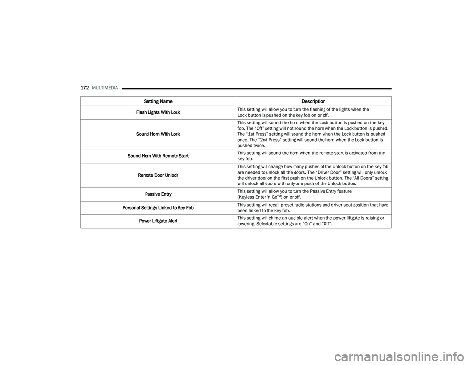
Flash Lights With Lock This setting will allow you to turn the flashing of the lights when the
Lock button is pushed on the key fob on or off.
Sound Horn With Lock This setting will sound the horn when the Lock button is pushed on the key
fob. The “Off” setting will not sound the horn when the Lock button is pushed.
The “1st Press” setting will sound the horn when the Lock button is pushed
once. The “2nd Press” setting will sound the horn when the Lock button is
pushed twice.
Sound Horn With Remote Start This setting will sound the horn when the remote start is activated from the
key fob.
Remote Door Unlock This setting will change how many pushes of the Unlock button on the key fob
are needed to unlock all the doors. The “Driver Door” setting will only unlock
the driver door on the first push on the Unlock button. The “All Doors” setting
will unlock all doors with only one push of the Unlock button.
Passive Entry This setting will allow you to turn the Passive Entry feature
(Keyless Enter ‘n Go™) on or off.
Personal Settings Linked to Key Fob This setting will recall preset radio stations and driver seat position that have
been linked to the key fob.
Power Liftgate Alert This setting will chime an audible alert when the power liftgate is raising or
lowering. Selectable settings are “On” and “Off”.
Setting Name
Description
22_WD_OM_EN_USC_t.book Page 172
Page 175 of 332
MULTIMEDIA173
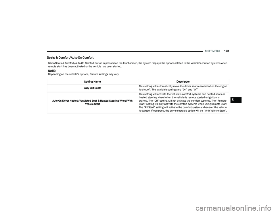
Seats & Comfort/Auto-On Comfort
When Seats & Comfort/Auto-On Comfort button is pressed on the touchscreen, the system displays the options related to the vehicle’s comfort systems when
remote start has been activated or the vehicle has been started.
NOTE:Depending on the vehicle’s options, feature settings may vary.
Setting Name Description
Easy Exit SeatsThis setting will automatically move the driver seat rearward when the engine
is shut off. The available settings are “On” and “Off”.
Auto-On Driver Heated/Ventilated Seat & Heated Steering Wheel With Vehicle Start This setting will activate the vehicle’s comfort systems and heated seats or
heated steering wheel when the vehicle is remote started or ignition is
started. The “Off” setting will not activate the comfort systems. The “Remote
Start” setting will only activate the comfort systems when using Remote Start.
The “All Start” setting will activate the comfort systems whenever the vehicle
is started. If equipped, the only selectable option will be “With Vehicle Start”.
5
22_WD_OM_EN_USC_t.book Page 173
Page 248 of 332
246IN CASE OF EMERGENCY
14. Lower the jack to the fully closed position. Return the tools to the proper positions in the
tool bag. Fold the flap on the tool bag under
the tools and roll the tools in the bag
underneath the others. Use the hook and loop
fasteners to secure the tool bag to the jack
with the lug wrench on the forward side of the
jack. Expand the jack on the bracket by turning
the thumb screw clockwise until it is tight to
prevent rattles.
15. Reinstall the plastic plug into the floor of the cargo area. Roll up and store the Jack, Tool Kit
and Tire Changing Instructions. Reinstall the
cover for the jack in the rear storage bin.
16. Have the aluminum road wheel and tire repaired as soon as possible and properly
secure the spare tire, jack and tool kit.
JUMP STARTING
If your vehicle has a discharged battery, it can be
jump started using a set of jumper cables and a
battery in another vehicle, or by using a portable
battery booster pack. Jump starting can be
dangerous if done improperly, so please follow the
procedures in this section carefully.
NOTE:When using a portable battery booster pack, follow
the manufacturer's operating instructions and
precautions.
PREPARATIONS FOR JUMP START
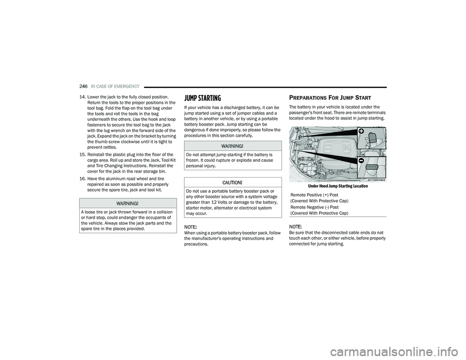
The battery in your vehicle is located under the
passenger's front seat. There are remote terminals
located under the hood to assist in jump starting.
Under Hood Jump Starting Location
NOTE:Be sure that the disconnected cable ends do not
touch each other, or either vehicle, before properly
connected for jump starting.
WARNING!
A loose tire or jack thrown forward in a collision
or hard stop, could endanger the occupants of
the vehicle. Always stow the jack parts and the
spare tire in the places provided.
WARNING!
Do not attempt jump starting if the battery is
frozen. It could rupture or explode and cause
personal injury.
CAUTION!
Do not use a portable battery booster pack or
any other booster source with a system voltage
greater than 12 Volts or damage to the battery,
starter motor, alternator or electrical system
may occur.Remote Positive (+) Post
(Covered With Protective Cap)
Remote Negative (-) Post
(Covered With Protective Cap)
22_WD_OM_EN_USC_t.book Page 246
Page 249 of 332
IN CASE OF EMERGENCY247
See the following steps to prepare for jump
starting:
1. Apply the parking brake, shift the automatic transmission into PARK (P) and turn the
ignition OFF.
2. Turn off the heater, radio, and all electrical accessories.
3. Remove the protective cover over the remote positive (+) battery post. Pull upward on the
cover to remove it.
4. Remove the protective cover over the remote negative (-) battery post.
5. If using another vehicle to jump start the battery, park the vehicle within the jumper
cable’s reach, apply the parking brake and
make sure the ignition is OFF.
JUMP STARTING PROCEDURE
NOTE:Make sure at all times that unused ends of jumper
cables are not contacting each other or either
vehicle while making connections.
Connecting The Jumper Cables
1. Connect the positive
(+) end of the jumper
cable to the remote positive (+)
post of the
discharged vehicle.
2. Connect the opposite end of the positive (+)
jumper cable to the positive (+) post of the
booster battery.
3. Connect the negative (-) end of the jumper
cable to the negative (-) post of the booster
battery.
4. Connect the opposite end of the negative (-)
jumper cable to the remote negative (-) post
(exposed metallic/unpainted post of the
discharge vehicle) located on the right hand
side next to the underhood fuse box.
WARNING!
Do not allow vehicles to touch each other as this
could establish a ground connection and
personal injury could result.
WARNING!
Take care to avoid the radiator cooling fan
whenever the hood is raised. It can start
anytime the ignition switch is ON. You can be
injured by moving fan blades.
Remove any metal jewelry such as rings,
watch bands and bracelets that could make
an inadvertent electrical contact. You could be
seriously injured.
Batteries contain sulfuric acid that can burn
your skin or eyes and generate hydrogen gas
which is flammable and explosive. Keep open
flames or sparks away from the battery.
WARNING!
Failure to follow this jump starting procedure
could result in personal injury or property
damage due to battery explosion.
CAUTION!
Failure to follow these procedures could result in
damage to the charging system of the booster
vehicle or the discharged vehicle.
WARNING!
Do not connect the jumper cable to the
negative (-) post of the discharged battery.
The resulting electrical spark could cause the
battery to explode and could result in personal
injury.
7
22_WD_OM_EN_USC_t.book Page 247
Page 250 of 332
248IN CASE OF EMERGENCY
5. Start the engine in the vehicle that has the booster battery, let the engine idle a few
minutes, and then start the engine in the
vehicle with the discharged battery.
6. Once the engine is started, follow the discon -
necting procedure.
Disconnecting The Jumper Cables
1. Disconnect the negative
(-) end of the jumper
cable from the remote negative (-)
post of the
discharged vehicle.
2. Disconnect the opposite end of the negative (-)
jumper cable from the negative (-) post of the
booster battery.
3. Disconnect the positive (+) end of the jumper
cable from the positive (+) post of the booster
battery. 4. Disconnect the opposite end of the positive
(+)
jumper cable from the remote positive (+) post
of the discharged vehicle.
5. Reinstall the protective covers over the remote positive (+) and negative (-) posts of the
discharged vehicle.
If frequent jump starting is required to start your
vehicle have the battery and charging system
tested at an authorized dealer.
REFUELING IN EMERGENCY – IF EQUIPPED
The vehicle is equipped with a refueling funnel for
a Cap-Less Fuel System. The fuel funnel can be
found in the rear cargo area with the jack and
tools. If refueling is necessary, while using an
approved gas can, insert the refueling funnel into
the filler neck opening. Take care to open both
flappers with the funnel to avoid spills.
CAUTION!
Do not run the booster vehicle engine above
2,000 RPM since it provides no charging benefit,
wastes fuel, and can damage booster vehicle
engine.
CAUTION!
Accessories plugged into the vehicle power
outlets draw power from the vehicle’s battery,
even when not in use (i.e., cellular devices, etc.).
Eventually, if plugged in long enough without
engine operation, the vehicle’s battery will
discharge sufficiently to degrade battery life
and/or prevent the engine from starting.
WARNING!
Never have any smoking materials lit in or
near the vehicle when the fuel door is open or
the tank is being filled.
Never add fuel when the engine is running.
This is in violation of most state and federal
fire regulations and may cause the Malfunc -
tion Indicator Light to turn on.
A fire may result if fuel is pumped into a
portable container that is inside of a vehicle.
You could be burned. Always place fuel
containers on the ground while filling.
22_WD_OM_EN_USC_t.book Page 248
Page 261 of 332
SERVICING AND MAINTENANCE259
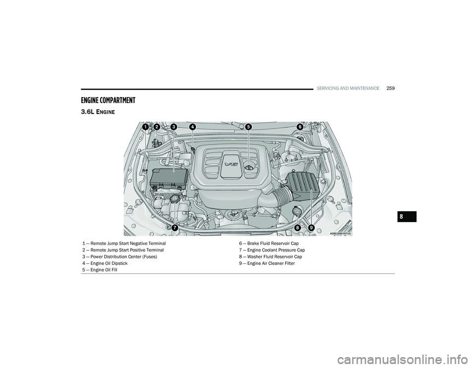
ENGINE COMPARTMENT
3.6L ENGINE
1 — Remote Jump Start Negative Terminal 6 — Brake Fluid Reservoir Cap
2 — Remote Jump Start Positive Terminal 7 — Engine Coolant Pressure Cap
3 — Power Distribution Center (Fuses) 8 — Washer Fluid Reservoir Cap
4 — Engine Oil Dipstick 9 — Engine Air Cleaner Filter
5 — Engine Oil Fill
8
22_WD_OM_EN_USC_t.book Page 259