window DODGE DURANGO 2022 User Guide
[x] Cancel search | Manufacturer: DODGE, Model Year: 2022, Model line: DURANGO, Model: DODGE DURANGO 2022Pages: 332, PDF Size: 19.82 MB
Page 58 of 332
56GETTING TO KNOW YOUR VEHICLE
Driver And Passenger Temperature
Buttons
These buttons provide the driver and passenger
with independent temperature control.
Push the Up button on the faceplate or
press and slide the temperature bar
towards the red arrow button on
the touchscreen for warmer
temperature settings.
Push the Down button on the faceplate or
press and slide the temperature bar
towards the blue arrow button on
the touchscreen for cooler
temperature settings.
SYNC Button
Press the SYNC button on the
touchscreen to toggle the SYNC feature
on/off. The SYNC indicator illuminates
when SYNC is on. SYNC is used to
synchronize the front passenger temperature and rear passenger temperature, mode, and blower
settings with the driver temperature, mode, and
blower settings. Changing the front passenger
temperature or rear passenger temperature,
mode, and blower settings while in SYNC will
automatically exit this feature.
NOTE:The SYNC setting is only available on the touch
-
screen.
Blower Control
Blower Control is used to regulate the
amount of air forced through the Climate
Control system. There are seven blower
speeds available. Adjusting the blower
will cause automatic mode to switch to manual
operation. The speeds can be selected using either
the blower control knob on the faceplate or the
buttons on the touchscreen.
Faceplate: The blower speed increases as you
turn the blower control knob clockwise from the
lowest blower setting. The blower speed
decreases as you turn the blower control knob
counterclockwise.
Touchscreen: Use the small blower icon to
reduce the blower setting and the large blower
icon to increase the blower setting. Blower
speed can also be selected by pressing the
blower bar area between the icons.
Mode Control
Select Mode by pressing the Mode
button on the faceplate, or one of the
Mode buttons on the touchscreen to
change the airflow distribution mode.
The airflow distribution mode can be adjusted so
air comes from the instrument panel outlets, floor
outlets, defrost outlets and demist outlets.
Panel Mode
Air comes from the outlets in the
instrument panel. Each of these outlets
can be individually adjusted to direct the
flow of air. The air vanes of the center
outlets and outboard outlets can be moved up and
down or side to side to regulate airflow direction.
There is a shut-off wheel located below the air
vanes to shut off or adjust the amount of airflow
from these outlets.
Bi-Level Mode
Air comes from the instrument panel
outlets and floor outlets. A slight amount
of air is directed through the defrost and
side window demister outlets.
NOTE:Bi-Level mode is designed under comfort condi -
tions to provide cooler air out of the panel outlets
and warmer air from the floor outlets.
Do not use scrapers, sharp instruments, or
abrasive window cleaners on the interior
surface of the window.
Keep all objects a safe distance from the
window.
CAUTION!
22_WD_OM_EN_USC_t.book Page 56
Page 59 of 332
GETTING TO KNOW YOUR VEHICLE57
Floor Mode
Air comes from the floor outlets. A slight
amount of air is directed through the
defrost and side window demister
outlets.
Mix Mode
Air is directed through the floor, defrost,
and side window demister outlets. This
setting works best in cold or snowy
conditions that require extra heat to the
windshield. This setting is good for maintaining
comfort while reducing moisture on the
windshield.
Climate Control OFF Button
Press and release this button to turn the
Climate Control ON/OFF.
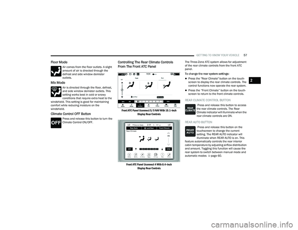
Controlling The Rear Climate Controls
From The Front ATC Panel
Front ATC Panel Uconnect 5/5 NAV With 10.1–inch
Display Rear Controls
Front ATC Panel Uconnect 4 With 8.4–inch Display Rear Controls
The Three-Zone ATC system allows for adjustment
of the rear climate controls from the front ATC
panel.
To change the rear system settings:
Press the "Rear Climate" button on the touch
-
screen to display the rear climate controls. The
control functions now operate the rear system.
Press the “Front Climate” button on the touch-
screen to return to the front climate controls.
REAR CLIMATE CONTROL BUTTON
Press and release this button to access
the rear climate controls. The Rear
Climate indicator will illuminate when the
rear climate controls are ON.
REAR AUTO BUTTON
Press and release this button on the
touchscreen to change the current
setting. The REAR AUTO indicator will
illuminate when REAR AUTO is on. This
feature automatically controls the rear interior
cabin temperature by adjusting airflow distribution
and amount. Toggling this function will cause the
rear system to switch between manual mode and
automatic modes Ú page 60.
2
22_WD_OM_EN_USC_t.book Page 57
Page 63 of 332
GETTING TO KNOW YOUR VEHICLE61
OPERATING TIPS
Refer to the chart at the end of this section for
suggested control settings for various weather
conditions.
Summer Operation
The engine cooling system must be protected with
a high-quality antifreeze coolant to provide proper
corrosion protection and to protect against engine
overheating. A solution of 50% OAT (Organic
Additive Technology) coolant that meets the
requirements of FCA Material Standard MS.90032
and 50% water is recommended Úpage 312.
Winter Operation
To ensure the best possible heater and defroster
performance, make sure the engine cooling
system is functioning properly and the proper
amount, type, and concentration of coolant is
used. Use of the Air Recirculation mode during
Winter months is not recommended, because it
may cause window fogging.
Vacation/Storage
For information on maintaining the Climate Control
system when the vehicle is being stored for an
extended period of time, see Úpage 304.
Window Fogging
Interior fogging on the windshield can be quickly
removed by turning the mode selector to Defrost.
The Defrost/Floor mode can be used to maintain a
clear windshield and provide sufficient heating.
If side window fogging becomes objectionable,
increase blower speed to improve airflow and
clearing of the side windows. Vehicle windows tend
to fog on the inside in mild but rainy or humid
weather.
NOTE:
Recirculate without A/C should not be used for
long periods, as fogging may occur.
Automatic Temperature Controls (ATC) will auto -
matically adjust the climate control settings to
reduce or eliminate window fogging on the front
windshield. When this occurs, recirculation will
be unavailable.
Outside Air Intake
Make sure the air intake, located directly in front of
the windshield, is free of obstructions, such as
leaves. Leaves collected in the air intake may
reduce airflow, and if they enter the air distribution
box, they could plug the water drains. In Winter
months, make sure the air intake is clear of ice,
slush, and snow.
Cabin Air Filter
The Climate Control system filters out dust and
pollen from the air. Contact an authorized dealer to
service your cabin air filter, and to have it replaced
when needed Ú page 262.
Stop/Start System — If Equipped
While in an Autostop, the Climate Control system
may automatically adjust airflow to maintain cabin
comfort. Customer settings will be maintained
upon return to an engine running condition.
CAUTION!
Interior air enters the Rear Automatic
Temperature Control system through an intake
grille, located in the right side trim panel behind
the third row seats. The heater outlets are
located in the right side trim panel, just behind
the passenger second row door. Do not block or
place objects directly in front of the inlet grille or
heater outlets. The electrical system could
overload causing damage to the blower motor.
2
22_WD_OM_EN_USC_t.book Page 61
Page 64 of 332
62GETTING TO KNOW YOUR VEHICLE
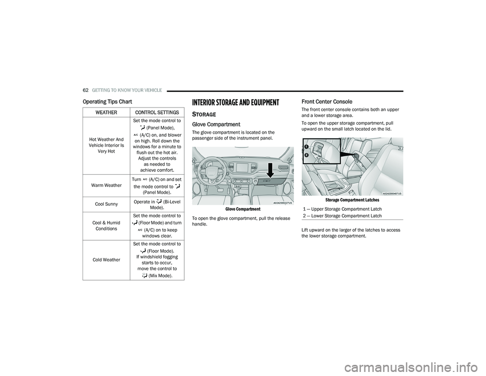
Operating Tips ChartINTERIOR STORAGE AND EQUIPMENT
STORAGE
Glove Compartment
The glove compartment is located on the
passenger side of the instrument panel.
Glove Compartment
To open the glove compartment, pull the release
handle.
Front Center Console
The front center console contains both an upper
and a lower storage area.
To open the upper storage compartment, pull
upward on the small latch located on the lid.
Storage Compartment Latches
Lift upward on the larger of the latches to access
the lower storage compartment.WEATHER CONTROL SETTINGS
Hot Weather And
Vehicle Interior Is Very Hot Set the mode control to
(Panel Mode),
(A/C) on, and blower
on high. Roll down the
windows for a minute to flush out the hot air. Adjust the controls as needed to
achieve comfort.
Warm Weather Turn (A/C) on and set
the mode control to (Panel Mode).
Cool Sunny Operate in (Bi-Level
Mode).
Cool & Humid Conditions Set the mode control to
(Floor Mode) and turn (A/C) on to keep
windows clear.
Cold Weather Set the mode control to
(Floor Mode).
If windshield fogging starts to occur,
move the control to
(Mix Mode).
1 — Upper Storage Compartment Latch
2 — Lower Storage Compartment Latch
22_WD_OM_EN_USC_t.book Page 62
Page 71 of 332
GETTING TO KNOW YOUR VEHICLE69
WIRELESS CHARGING PAD —
I
F EQUIPPED
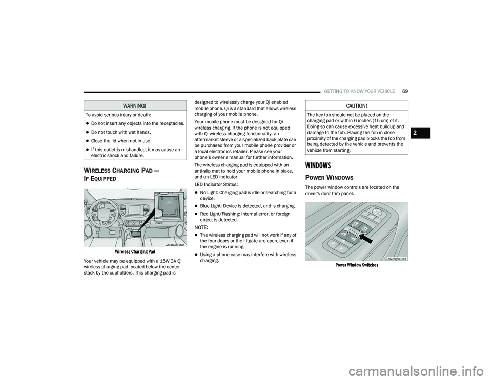
Wireless Charging Pad
Your vehicle may be equipped with a 15W 3A Qi
wireless charging pad located below the center
stack by the cupholders. This charging pad is designed to wirelessly charge your Qi enabled
mobile phone. Qi is a standard that allows wireless
charging of your mobile phone.
Your mobile phone must be designed for Qi
wireless charging. If the phone is not equipped
with Qi wireless charging functionality, an
aftermarket sleeve or a specialized back plate can
be purchased from your mobile phone provider or
a local electronics retailer. Please see your
phone’s owner’s manual for further information.
The wireless charging pad is equipped with an
anti-slip mat to hold your mobile phone in place,
and an LED indicator.
LED Indicator Status:
No Light: Charging pad is idle or searching for a
device.
Blue Light: Device is detected, and is charging.
Red Light/Flashing: Internal error, or foreign
object is detected.
NOTE:
The wireless charging pad will not work if any of
the four doors or the liftgate are open, even if
the engine is running.
Using a phone case may interfere with wireless
charging.
WINDOWS
POWER WINDOWS
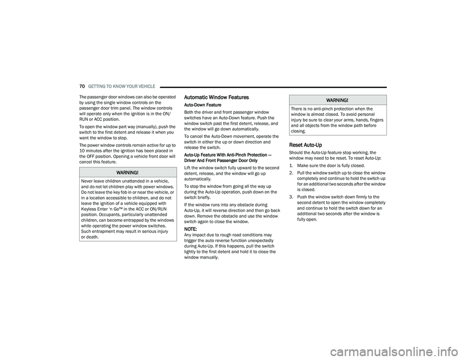
The power window controls are located on the
driver's door trim panel.
Power Window Switches
WARNING!
To avoid serious injury or death:
Do not insert any objects into the receptacles.
Do not touch with wet hands.
Close the lid when not in use.
If this outlet is mishandled, it may cause an
electric shock and failure.
CAUTION!
The key fob should not be placed on the
charging pad or within 6 inches (15 cm) of it.
Doing so can cause excessive heat buildup and
damage to the fob. Placing the fob in close
proximity of the charging pad blocks the fob from
being detected by the vehicle and prevents the
vehicle from starting.
2
22_WD_OM_EN_USC_t.book Page 69
Page 72 of 332
70GETTING TO KNOW YOUR VEHICLE
The passenger door windows can also be operated
by using the single window controls on the
passenger door trim panel. The window controls
will operate only when the ignition is in the ON/
RUN or ACC position.
To open the window part way (manually), push the
switch to the first detent and release it when you
want the window to stop.
The power window controls remain active for up to
10 minutes after the ignition has been placed in
the OFF position. Opening a vehicle front door will
cancel this feature.
Automatic Window Features
Auto-Down Feature
Both the driver and front passenger window
switches have an Auto-Down feature. Push the
window switch past the first detent, release, and
the window will go down automatically.
To cancel the Auto-Down movement, operate the
switch in either the up or down direction and
release the switch.
Auto-Up Feature With Anti-Pinch Protection —
Driver And Front Passenger Door Only
Lift the window switch fully upward to the second
detent, release, and the window will go up
automatically.
To stop the window from going all the way up
during the Auto-Up operation, push down on the
switch briefly.
If the window runs into any obstacle during
Auto-Up, it will reverse direction and then go back
down. Remove the obstacle and use the window
switch again to close the window.
NOTE:Any impact due to rough road conditions may
trigger the auto reverse function unexpectedly
during Auto-Up. If this happens, pull the switch
lightly to the first detent and hold it to close the
window manually.
Reset Auto-Up
Should the Auto-Up feature stop working, the
window may need to be reset. To reset Auto-Up:
1. Make sure the door is fully closed.
2. Pull the window switch up to close the window completely and continue to hold the switch up
for an additional two seconds after the window
is closed.
3. Push the window switch down firmly to the second detent to open the window completely
and continue to hold the switch down for an
additional two seconds after the window is
fully open.
WARNING!
Never leave children unattended in a vehicle,
and do not let children play with power windows.
Do not leave the key fob in or near the vehicle, or
in a location accessible to children, and do not
leave the ignition of a vehicle equipped with
Keyless Enter ‘n Go™ in the ACC or ON/RUN
position. Occupants, particularly unattended
children, can become entrapped by the windows
while operating the power window switches.
Such entrapment may result in serious injury
or death.
WARNING!
There is no anti-pinch protection when the
window is almost closed. To avoid personal
injury be sure to clear your arms, hands, fingers
and all objects from the window path before
closing.
22_WD_OM_EN_USC_t.book Page 70
Page 73 of 332
GETTING TO KNOW YOUR VEHICLE71
Window Lockout Switch
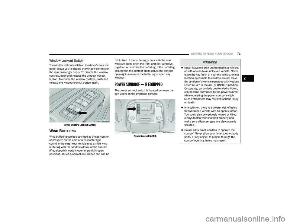
The window lockout switch on the driver's door trim
panel allows you to disable the window controls on
the rear passenger doors. To disable the window
controls, push and release the window lockout
button. To enable the window controls, push and
release the window lockout button again.
Power Window Lockout Switch
WIND BUFFETING
Wind buffeting can be described as the perception
of pressure on the ears or a helicopter-type
sound in the ears. Your vehicle may exhibit wind
buffeting with the windows down, or the sunroof
(if equipped) in certain open or partially open
positions. This is a normal occurrence and can be minimized. If the buffeting occurs with the rear
windows open, open the front and rear windows
together to minimize the buffeting. If the buffeting
occurs with the sunroof open, adjust the sunroof
opening to minimize the buffeting or open any
window.
POWER SUNROOF — IF EQUIPPED
The power sunroof switch is located between the
sun visors on the overhead console.
Power Sunroof Switch
WARNING!
Never leave children unattended in a vehicle,
or with access to an unlocked vehicle. Never
leave the key fob in or near the vehicle, or in a
location accessible to children. Do not leave
the ignition of a vehicle equipped with Keyless
Enter ‘n Go™ in the ACC or ON/RUN position.
Occupants, particularly unattended children,
can become entrapped by the power sunroof
while operating the power sunroof switch.
Such entrapment may result in serious injury
or death.
In a collision, there is a greater risk of being
thrown from a vehicle with an open sunroof.
You could also be seriously injured or killed.
Always fasten your seat belt properly and
make sure all passengers are also properly
secured.
Do not allow small children to operate the
sunroof. Never allow your fingers, other body
parts, or any object, to project through the
sunroof opening. Injury may result.
2
22_WD_OM_EN_USC_t.book Page 71
Page 76 of 332
74GETTING TO KNOW YOUR VEHICLE
(Continued)
When the liftgate button on the key fob is pushed
two times, the turn signals will flash to signal that
the liftgate is opening or closing (if Flash Lamps
with Lock is enabled in the Uconnect settings), and
the liftgate chime will be audible. The chime can be
turned on or off through the Uconnect Settings
Ú
page 156.
NOTE:
In the event of a power malfunction to the lift -
gate, an emergency liftgate latch release can be
used to open the liftgate. The emergency liftgate
latch release can be accessed through a snap-in
cover located on the liftgate trim panel.
If liftgate is left open for an extended period of
time, the liftgate may need to be closed manu -
ally to reset power liftgate functionality.
NOTE:
The power liftgate buttons will not operate if the
vehicle is in gear or the vehicle speed is above
0 mph (0 km/h).
The power liftgate will not operate in tempera -
tures below −22°F (−30°C) or temperatures
above 150°F (65°C). Be sure to remove any
buildup of snow or ice from the liftgate before
pushing any of the power liftgate switches.
If anything obstructs the power liftgate while it is
closing or opening, the liftgate will automatically
reverse to the closed or open position. After
multiple obstructions in the same cycle, the lift -
gate will automatically stop and must be opened
or closed manually.
There are also pinch sensors attached to the
side of the liftgate. Light pressure anywhere
along these strips will cause the liftgate to
return to the open position.
If the liftgate is only partially open, push the lift -
gate button on the key fob twice to operate the
liftgate.
If the liftgate release handle is pushed while the
power liftgate is opening, the liftgate motor will
disengage to allow manual operation.
CARGO AREA FEATURES
Cargo Storage
There is a removable storage bin located on the
left side of the rear cargo area.
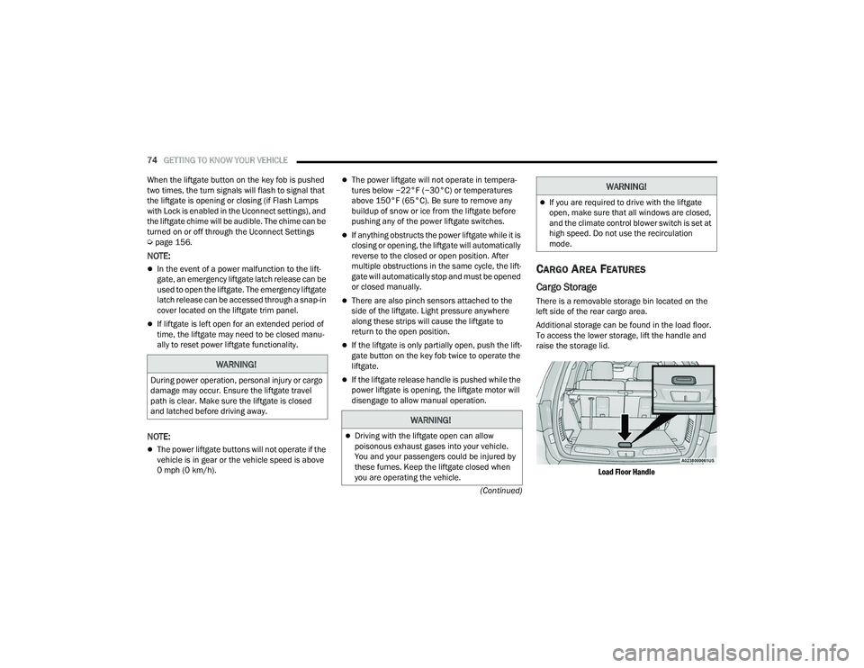
Additional storage can be found in the load floor.
To access the lower storage, lift the handle and
raise the storage lid.
Load Floor Handle
WARNING!
During power operation, personal injury or cargo
damage may occur. Ensure the liftgate travel
path is clear. Make sure the liftgate is closed
and latched before driving away.
WARNING!
Driving with the liftgate open can allow
poisonous exhaust gases into your vehicle.
You and your passengers could be injured by
these fumes. Keep the liftgate closed when
you are operating the vehicle.
If you are required to drive with the liftgate
open, make sure that all windows are closed,
and the climate control blower switch is set at
high speed. Do not use the recirculation
mode.
WARNING!
22_WD_OM_EN_USC_t.book Page 74
Page 101 of 332
99
(Continued)
(Continued)
STARTING AND OPERATING
STARTING THE ENGINE
Before starting your vehicle, adjust your seat,
adjust the inside and outside mirrors, fasten your
seat belt, and if present, instruct all other
occupants to buckle their seat belts.
AUTOMATIC TRANSMISSION
The gear selector must be in the NEUTRAL (N) or
PARK (P) position before you can start the engine.
Apply the brakes before shifting into any driving
gear.
NORMAL STARTING
To Turn On The Engine Using The ENGINE START/
STOP Button
1. The transmission must be in PARK (P).
2. Press and hold the brake pedal while pushing
the ENGINE START/STOP button once.
3. The system starts the vehicle. If the vehicle fails to start, the starter will disengage
automatically after 10 seconds.
4. If you wish to stop the cranking of the engine prior to the engine starting, push the ENGINE
START/STOP button again.
WARNING!
Before exiting a vehicle, always come to a
complete stop, then shift the automatic trans -
mission into PARK and apply the parking
brake.
Always make sure the keyless ignition node is
in the OFF position, key fob is removed from
the vehicle and vehicle is locked.
Never leave children alone in a vehicle, or with
access to an unlocked vehicle. Leaving chil -
dren in a vehicle unattended is dangerous for
a number of reasons. A child or others could
be seriously or fatally injured. Children should
be warned not to touch the parking brake,
brake pedal or the gear selector.
Do not leave the key fob in or near the vehicle,
or in a location accessible to children, and do
not leave the ignition of a vehicle equipped
with Keyless Enter ‘n Go™ in the ACC or ON/
RUN position. A child could operate power
windows, other controls, or move the vehicle.
Do not leave children or animals inside parked
vehicles in hot weather. Interior heat build-up
may cause serious injury or death.
CAUTION!
Damage to the transmission may occur if the
following precautions are not observed:
Do not shift from REVERSE (R), PARK, or
NEUTRAL into any forward gear when the
engine is above idle speed.
WARNING!
Shift into or out of PARK or REVERSE only after
the vehicle has come to a complete stop and
the engine is at idle speed.
Before shifting into any gear, make sure your
foot is firmly on the brake pedal.
CAUTION!
4
22_WD_OM_EN_USC_t.book Page 99
Page 105 of 332
STARTING AND OPERATING103
(Continued)
NOTE:A new engine may consume some oil during its first
few thousand miles (kilometers) of operation. This
should be considered a normal part of the break-in
and not interpreted as a problem. Please check
your oil level with the engine oil indicator often
during the break-in period. Add oil as required.
PARKING BRAKE
Before leaving the vehicle, make sure that the
parking brake is fully applied and place the gear
selector in the PARK (P) position.
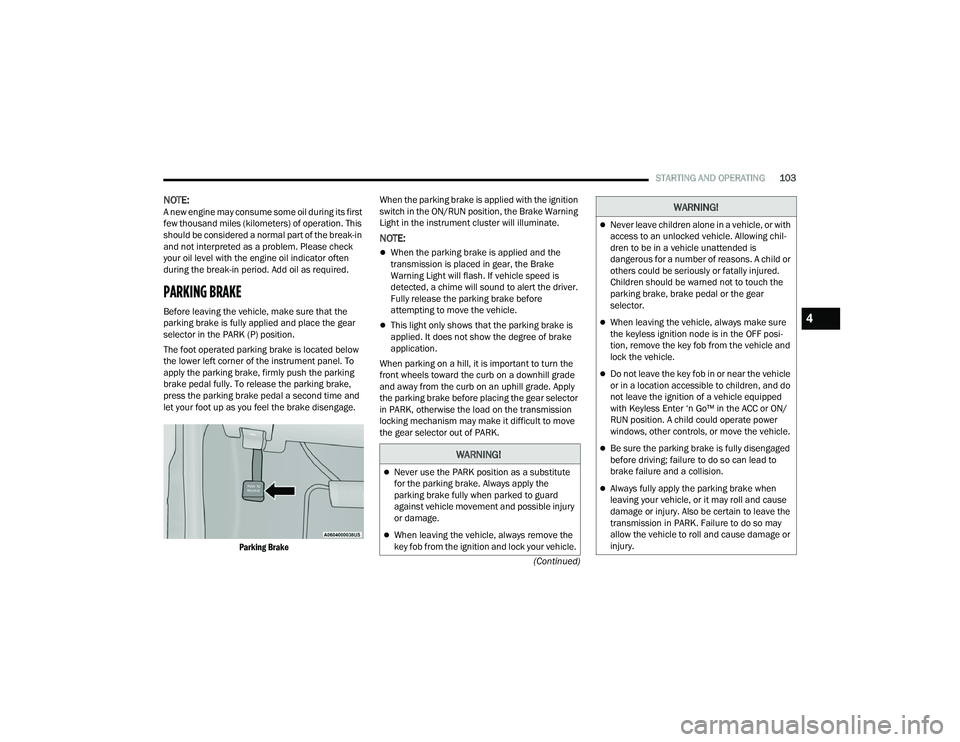
The foot operated parking brake is located below
the lower left corner of the instrument panel. To
apply the parking brake, firmly push the parking
brake pedal fully. To release the parking brake,
press the parking brake pedal a second time and
let your foot up as you feel the brake disengage.
Parking Brake
When the parking brake is applied with the ignition
switch in the ON/RUN position, the Brake Warning
Light in the instrument cluster will illuminate.
NOTE:
When the parking brake is applied and the
transmission is placed in gear, the Brake
Warning Light will flash. If vehicle speed is
detected, a chime will sound to alert the driver.
Fully release the parking brake before
attempting to move the vehicle.
This light only shows that the parking brake is
applied. It does not show the degree of brake
application.
When parking on a hill, it is important to turn the
front wheels toward the curb on a downhill grade
and away from the curb on an uphill grade. Apply
the parking brake before placing the gear selector
in PARK, otherwise the load on the transmission
locking mechanism may make it difficult to move
the gear selector out of PARK.
WARNING!
Never use the PARK position as a substitute
for the parking brake. Always apply the
parking brake fully when parked to guard
against vehicle movement and possible injury
or damage.
When leaving the vehicle, always remove the
key fob from the ignition and lock your vehicle.
Never leave children alone in a vehicle, or with
access to an unlocked vehicle. Allowing chil -
dren to be in a vehicle unattended is
dangerous for a number of reasons. A child or
others could be seriously or fatally injured.
Children should be warned not to touch the
parking brake, brake pedal or the gear
selector.
When leaving the vehicle, always make sure
the keyless ignition node is in the OFF posi -
tion, remove the key fob from the vehicle and
lock the vehicle.
Do not leave the key fob in or near the vehicle
or in a location accessible to children, and do
not leave the ignition of a vehicle equipped
with Keyless Enter ‘n Go™ in the ACC or ON/
RUN position. A child could operate power
windows, other controls, or move the vehicle.
Be sure the parking brake is fully disengaged
before driving; failure to do so can lead to
brake failure and a collision.
Always fully apply the parking brake when
leaving your vehicle, or it may roll and cause
damage or injury. Also be certain to leave the
transmission in PARK. Failure to do so may
allow the vehicle to roll and cause damage or
injury.
WARNING!
4
22_WD_OM_EN_USC_t.book Page 103