headrest DODGE DURANGO 2022 Owners Manual
[x] Cancel search | Manufacturer: DODGE, Model Year: 2022, Model line: DURANGO, Model: DODGE DURANGO 2022Pages: 332, PDF Size: 19.82 MB
Page 41 of 332

GETTING TO KNOW YOUR VEHICLE39
Head Restraint Removal — Rear Seats
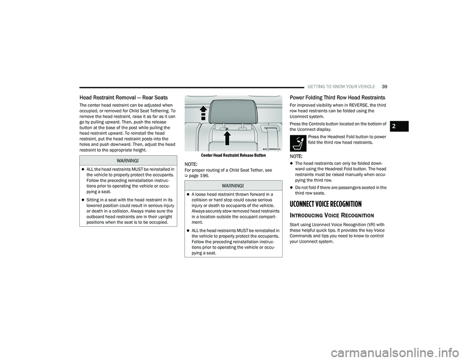
The center head restraint can be adjusted when
occupied, or removed for Child Seat Tethering. To
remove the head restraint, raise it as far as it can
go by pulling upward. Then, push the release
button at the base of the post while pulling the
head restraint upward. To reinstall the head
restraint, put the head restraint posts into the
holes and push downward. Then, adjust the head
restraint to the appropriate height.
Center Head Restraint Release Button
NOTE:For proper routing of a Child Seat Tether, see
Úpage 196.
Power Folding Third Row Head Restraints
For improved visibility when in REVERSE, the third
row head restraints can be folded using the
Uconnect system.
Press the Controls button located on the bottom of
the Uconnect display.
Press the Headrest Fold button to power
fold the third row head restraints.
NOTE:
The head restraints can only be folded down -
ward using the Headrest Fold button. The head
restraints must be raised manually when occu -
pying the third row.
Do not fold if there are passengers seated in the
third row seats.
UCONNECT VOICE RECOGNITION
INTRODUCING VOICE RECOGNITION
Start using Uconnect Voice Recognition (VR) with
these helpful quick tips. It provides the key Voice
Commands and tips you need to know to control
your Uconnect system.
WARNING!
ALL the head restraints MUST be reinstalled in
the vehicle to properly protect the occupants.
Follow the preceding reinstallation instruc -
tions prior to operating the vehicle or occu -
pying a seat.
Sitting in a seat with the head restraint in its
lowered position could result in serious injury
or death in a collision. Always make sure the
outboard head restraints are in their upright
positions when the seat is to be occupied.
WARNING!
A loose head restraint thrown forward in a
collision or hard stop could cause serious
injury or death to occupants of the vehicle.
Always securely stow removed head restraints
in a location outside the occupant compart -
ment.
ALL the head restraints MUST be reinstalled in
the vehicle to properly protect the occupants.
Follow the preceding reinstallation instruc -
tions prior to operating the vehicle or occu -
pying a seat.
2
22_WD_OM_EN_USC_t.book Page 39
Page 232 of 332

230SAFETY
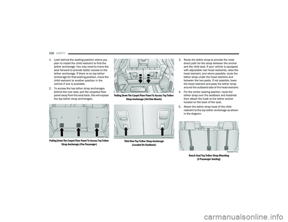
1. Look behind the seating position where you plan to install the child restraint to find the
tether anchorage. You may need to move the
seat forward to provide better access to the
tether anchorage. If there is no top tether
anchorage for that seating position, move the
child restraint to another position in the
vehicle if one is available.
2. To access the top tether strap anchorages behind the rear seat, pull the carpeted floor
panel away from the seat back, this will expose
the top tether strap anchorages.
Pulling Down The Carpet Floor Panel To Access Top Tether Strap Anchorage (Five Passenger) Pulling Down The Carpet Floor Panel To Access Top Tether
Strap Anchorage (3rd Row Bench)
Third Row Top Tether Strap Anchorage (Located On Seatback)
3. Route the tether strap to provide the most
direct path for the strap between the anchor
and the child seat. If your vehicle is equipped
with adjustable rear head restraints, raise the
head restraint, and where possible, route the
tether strap under the head restraint and
between the two posts. If not possible, lower
the head restraint and pass the tether strap
around the outboard side of the head restraint.
4. For the center seating position, route the tether strap over the seatback and headrest
then attach the hook to the tether anchor
located on the back of the seat.
5. Attach the tether strap hook of the child restraint to the top tether anchorage as shown
in the diagram.
Bench Seat Top Tether Strap Mounting (5 Passenger Seating)
22_WD_OM_EN_USC_t.book Page 230
Page 281 of 332

SERVICING AND MAINTENANCE279
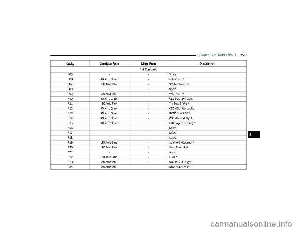
F05 ––Spare
F06 40 Amp Green –ABS Pump *
F07 30 Amp Pink –Starter Solenoid
F08 ––Spare
F09 30 Amp Pink –VAC PUMP *
F10 40 Amp Green –CBC #2 / EXT Light
F11 30 Amp Pink –Trlr Tow Brake *
F12 40 Amp Green –CBC #3 / Pwr Locks
F13 40 Amp Green –HVAC BLWR MTR
F14 40 Amp Green –CBC #4 / Ext Light
F15 40 Amp Green –LTR Engine Cooling *
F16 ––Spare
F17 ––Spare
F18 ––Spare
F19 20 Amp Blue –Solenoid Headrest *
F20 30 Amp Pink –Pass Door Mod
F21 ––Spare
F22 20 Amp Blue –ECM *
F23 30 Amp Pink –CBC #1 / Int Light
F24 30 Amp Pink –Driver Door Mod
Cavity Cartridge Fuse Micro Fuse Description
* If Equipped
8
22_WD_OM_EN_USC_t.book Page 279