ESP DODGE DURANGO 2023 User Guide
[x] Cancel search | Manufacturer: DODGE, Model Year: 2023, Model line: DURANGO, Model: DODGE DURANGO 2023Pages: 328, PDF Size: 13.82 MB
Page 108 of 328
106STARTING AND OPERATING
When exiting the vehicle, always:
Apply the parking brake.
Shift the transmission into PARK.
Turn the ignition OFF.
Remove the key fob from the vehicle.
The following indicators should be used to ensure
that you have properly engaged the transmission
into the PARK position:
When shifting into PARK, push the lock button
on the gear selector and firmly move the
selector all the way forward until it stops and is
fully seated.
Look at the transmission gear position display
and verify that it indicates the PARK position (P),
and is not blinking.
With brake pedal released, verify that the gear
selector will not move out of PARK.
REVERSE (R)
This range is for moving the vehicle backward.
Shift into REVERSE only after the vehicle has come
to a complete stop.
NEUTRAL (N)
Use this range when the vehicle is standing for
prolonged periods with the engine running. Apply
the parking brake and shift the transmission into
PARK (P) if you must exit the vehicle.
DRIVE (D)
This range should be used for most city and
highway driving. It provides the smoothest upshifts
and downshifts, and the best fuel economy. The
transmission automatically upshifts through all
forward gears.
When frequent transmission shifting occurs (such
as when operating the vehicle under heavy loading
conditions, in hilly terrain, traveling into strong
head winds, or while towing a heavy trailer), use
the AutoStick shift control to select a lower gear
Ú page 107. Under these conditions, using a lower
gear will improve performance and extend
transmission life by reducing excessive shifting
and heat buildup.
During cold temperatures, transmission operation
may be modified depending on engine and
transmission temperature as well as vehicle
speed. This feature improves warm up time of the
engine and transmission to achieve maximum
efficiency. Engagement of the torque converter
clutch is inhibited until the transmission fluid is
warm. Normal operation will resume once the
transmission temperature has risen to a suitable
level.
CAUTION!
Before moving the transmission gear selector
out of PARK, you must start the engine, and
also press the brake pedal. Otherwise,
damage to the gear selector could result.
DO NOT race the engine when shifting from
PARK or NEUTRAL into another gear range, as
this can damage the drivetrain.
WARNING!
Do not coast in NEUTRAL and never turn off the
ignition to coast down a hill. These are unsafe
practices that limit your response to changing
traffic or road conditions. You might lose control
of the vehicle and have a collision.
CAUTION!
Towing the vehicle, coasting, or driving for any
other reason with the transmission in NEUTRAL
can cause severe transmission damage.
For Recreational Towing Ú page 146.
For Towing A Disabled Vehicle Ú page 246.
23_WD_OM_EN_USC_t.book Page 106
Page 110 of 328
108STARTING AND OPERATING
AutoStick mode has the following operational
benefits:
The transmission will automatically downshift
as the vehicle slows (to prevent engine lugging)
and will display the current gear.
The transmission will automatically downshift to
FIRST gear when coming to a stop. After a stop,
the driver should manually upshift (+) the trans -
mission as the vehicle is accelerated.
You can start out, from a stop, in FIRST or
SECOND gear. Tapping (+) at a stop will allow
starting in SECOND gear. Starting out in
SECOND gear can be helpful in snowy or icy
conditions.
If a requested downshift would cause the
engine to over-speed, that shift will not occur.
The system will ignore attempts to upshift at too
low of a vehicle speed.
Holding the (-) paddle pressed, or holding the
gear selector in the (-) position, will downshift
the transmission to the lowest gear possible at
the current speed.
Transmission shifting will be more noticeable
when AutoStick is enabled.
The system may revert to automatic shift mode
if a fault or overheat condition is detected. To disengage AutoStick mode, return the gear
selector to the DRIVE (D) position, or press and
hold the (+) paddle shifter until "D" is indicated in
the instrument cluster. You can shift in or out of
AutoStick mode at any time without taking your
foot off the accelerator pedal.
SPORT MODE — IF EQUIPPED
Your vehicle is equipped with a SPORT Mode
feature. The engine, transmission, and steering
systems are all set to their SPORT settings. SPORT
Mode will provide improved throttle response and
modified transmission shift points for an enhanced
driving experience, as well as greater amount of
steering feel. This mode may be activated and
deactivated by pushing the SPORT button on the
instrument panel switch bank.
ALL-WHEEL DRIVE OPERATION
SINGLE-SPEED OPERATING
I
NSTRUCTIONS/PRECAUTIONS —
I
F EQUIPPED
This system contains a single-speed (HI range only)
transfer case, which provides convenient full-time
All-Wheel Drive (AWD). No driver interaction is
required. The Brake Traction Control (BTC) System,
which combines standard ABS and Traction
Control, provides resistance to any wheel that is
slipping to allow additional torque transfer to
wheels with traction.
NOTE:This system is not appropriate for conditions where
AWD LOW is recommended Ú page 150.
WARNING!
Do not downshift for additional engine braking
on a slippery surface. The drive wheels could
lose their grip and the vehicle could skid,
causing a collision or personal injury.
23_WD_OM_EN_USC_t.book Page 108
Page 115 of 328
STARTING AND OPERATING113
4. Allow vehicle to sit and cool for at least 30 minutes. If an infrared thermal gun is
available, allow rotors to cool to 200°F
(93.3°C) before returning to the track.
5. There should be a thin layer of ash when inspecting the brake pads. Having the ash
layer go more than half the thickness of the
pad material is a sign of an overly aggressive
burnish.
6. Occasionally, a second burnish session is required. If the brake pads begin to emit an
odor during the next track session, reduce
vehicle speed and braking deceleration rate to
burnish targets and follow steps 2-4.
7. New brake pads installed on old rotors require a burnish. New rotors installed with old brake
pads should be burnished at the track or
driven for 300 miles (485 km) of city driving to
develop an adequate lining transfer layer on
the rotor surface prior to track use.
8. Rotors that pulsate during track use should be replaced.
NOTE:Resurfacing of the rotors is not recommended, as
it removes mass from the rotor, reducing its
thermal capacity. Resurfacing also thins the rotor
cheek, making it less robust and increasing the
likelihood of pulsation in further track use.
FUEL SAVER TECHNOLOGY 5.7L ONLY —
IF EQUIPPED
This feature offers improved fuel economy by
shutting off four of the engine's eight cylinders
during light load and cruise conditions. The system
is automatic with no driver inputs.
NOTE:This system may take some time to return to full
functionality after a battery disconnect.
POWER STEERING
The electric power steering system will provide
increased vehicle response and ease of
maneuverability. The power steering system
adapts to different driving conditions and adjusts
accordingly. Alternate electric power steering efforts can be
selected through the Uconnect System
Ú
page 153.
If the Electric Power Steering warning icon is
displayed and the “Service Power Steering” or the
“Power Steering Assist Off – Service System”
message is displayed within the instrument cluster
display, this indicates the vehicle needs to be
taken to the dealer for service Ú page 88.
NOTE:
Even if the power steering assistance is no
longer operational, it is still possible to steer the
vehicle. Under these conditions there will be a
substantial increase in steering effort, espe -
cially at low speeds and during parking maneu -
vers.
If the condition persists, see an authorized
dealer for service.
If the Steering icon is displayed and the “Power
Steering System Over Temp” message is displayed
on the instrument cluster screen, this indicates an
over temperature condition in the power steering
system. Once driving conditions are safe, pull over
and let the vehicle idle for a few moments until the
icon and message turn off.
WARNING!
Continued operation with reduced assist could
pose a safety risk to yourself and others. Service
should be obtained as soon as possible.
4
23_WD_OM_EN_USC_t.book Page 113
Page 119 of 328
STARTING AND OPERATING117
(Continued)
To Resume Speed
To resume a previously set speed, push the RES
button and release. Resume can be used at any
speed above 20 mph (32 km/h).
To Deactivate
A tap on the brake pedal, pushing the CANC button,
or normal brake pressure while slowing the vehicle
will deactivate the Cruise Control system without
erasing the set speed from memory.
The following conditions will also deactivate the
Cruise Control without erasing the set speed from
memory:
Vehicle parking brake is applied
Stability event occurs
Gear selector is moved out of DRIVE
Engine overspeed occurs Pushing the on/off button or placing the ignition in
the OFF position will erase the set speed from
memory.
ADAPTIVE CRUISE CONTROL (ACC)
Adaptive Cruise Control (ACC) increases the driving
convenience provided by Cruise Control while
traveling on highways and major roadways.
However, it is not a safety system and not designed
to prevent collisions. The Cruise Control function
performs differently
Ú page 115.
ACC will allow you to keep Cruise Control engaged
in light to moderate traffic conditions without the
constant need to reset your Cruise Control. ACC
utilizes a radar sensor and a forward facing
camera designed to detect a vehicle directly ahead
of you.
NOTE:
If the ACC sensor detects a vehicle ahead, ACC
will apply limited braking or acceleration (not to
exceed the original set speed) automatically to
maintain a preset following distance, while
matching the speed of the vehicle ahead.
Any chassis/suspension or tire size modifica -
tions to the vehicle will affect the performance
of the Adaptive Cruise Control and Forward Colli -
sion Warning system.
Fixed Speed Cruise Control (ACC not enabled)
will not detect vehicles directly ahead of you.
Always be aware of the feature selected
Ú page 312.WARNING!
Cruise Control can be dangerous where the
system cannot maintain a constant speed. Your
vehicle could go too fast for the conditions, and
you could lose control and have an accident. Do
not use Cruise Control in heavy traffic or on
roads that are winding, icy, snow-covered or
slippery.
WARNING!
Adaptive Cruise Control (ACC) is a conve -
nience system. It is not a substitute for active
driver involvement. It is always the driver’s
responsibility to be attentive of road, traffic,
and weather conditions, vehicle speed,
distance to the vehicle ahead and, most
importantly, brake operation to ensure safe
operation of the vehicle under all road condi -
tions. Your complete attention is always
required while driving to maintain safe control
of your vehicle. Failure to follow these warn -
ings can result in a collision and death or
serious personal injury.
The ACC system:
Does not react to pedestrians, oncoming
vehicles, and stationary objects (e.g., a
stopped vehicle in a traffic jam or a
disabled vehicle).
Cannot take street, traffic, and weather
conditions into account, and may be limited
upon adverse sight distance conditions.
4
23_WD_OM_EN_USC_t.book Page 117
Page 128 of 328
126STARTING AND OPERATING
Automatic emergency braking is not available if
the vehicle is in 4WD Low.
Automatic emergency braking will not be avail -
able if there is a faulted condition detected with
the ParkSense Park Assist system or the
Braking System Module.
The automatic emergency braking function may
only be applied if the vehicle deceleration is not
enough to avoid colliding with a detected
obstacle.
The automatic emergency braking function may
not be applied fast enough for obstacles that
move toward the rear of the vehicle from the left
and/or right sides.
The automatic emergency braking function can
be enabled/disabled from the Customer
Programmable Features section of the
Uconnect system.
ParkSense will retain its last known configura -
tion state for the automatic emergency braking
function through ignition cycles.
The rear automatic emergency braking function is
intended to assist the driver in avoiding possible
collisions with detected obstacles when backing
up in REVERSE gear.
NOTE:
The rear automatic emergency braking system
is for emergency braking to avoid an imminent collision. It is designed to assist the driver and
not to substitute the driver.
The driver must stay in full control of the
vehicle's acceleration and braking and is
responsible for the vehicle's movements.
For limitations of this system and
recommendations, see Ú page 130.
ParkSense will retain the last system state
(enabled or disabled) from the last ignition cycle
when the ignition is changed to the ON/RUN
position.
ParkSense can be active only when the gear
selector is in REVERSE or DRIVE. If ParkSense is
enabled at one of these gear selector positions,
the system will remain active until the vehicle
speed is increased to approximately 7 mph
(11 km/h) or above. The system will become active
again if the vehicle speed is decreased to speeds
less than approximately 6 mph (9 km/h). A display
warning will appear in the instrument cluster
display if the vehicle is in REVERSE and the speed
exceeds 7 mph (11 km/h).
PARKSENSE SENSORS
Six ParkSense sensors located in the front fascia/
bumper (if equipped) and six ParkSense sensors
(four when vehicle is not equipped with front
sensors) located in the rear fascia/bumper,
monitor the area in front and behind the vehicle
that is within the sensors’ field of view. The front sensors detect obstacles from approximately
12 inches (30 cm) up to 47 inches (120 cm) from
the front fascia/bumper. The rear sensors can
detect obstacles from approximately 12 inches
(30 cm) up to 79 inches (200 cm) from the rear
fascia/bumper. These distances depend on the
location, type and orientation of the obstacle in the
horizontal direction.
PARKSENSE DISPLAY
The warning display will turn on indicating the
system status when the vehicle is in REVERSE or
when the vehicle is in DRIVE and an obstacle has
been detected.
The system will indicate a detected obstacle by
showing a single arc in the left and/or right front or
rear regions based on the object’s distance and
location relative to the vehicle.
If an object is detected in the left and/or right rear
region, the display will show a single arc in the left
and/or right rear region and the system will
produce a tone. As the vehicle moves closer to the
object, the display will show the single arc moving
closer to the vehicle and the tone will change from
a single 1/2 second tone to slow, to fast, to
continuous.
23_WD_OM_EN_USC_t.book Page 126
Page 133 of 328
STARTING AND OPERATING131
(Continued)
result in the system not working properly. The
ParkSense system might not detect an obstacle
behind or in front of the fascia/bumper, or it
could provide a false indication that an obstacle
is behind or in front of the fascia/bumper.
Use the ParkSense switch to turn the ParkSense
system off if objects such as bicycle carriers,
trailer hitches, etc. are placed within 12 inches
(30 cm) of the rear fascia/bumper. Failure to do
so can result in the system misinterpreting a
close object as a sensor problem, causing the
“PARKSENSE UNAVAILABLE SERVICE
REQUIRED” message to be displayed in the
instrument cluster.
ParkSense should be disabled when the liftgate
is in the open position. An opened liftgate could
provide a false indication that an obstacle is
behind the vehicle.
LANESENSE — IF EQUIPPED
LANESENSE OPERATION
The LaneSense system is operational at speeds
above 37 mph (60 km/h) and below 112 mph
(180 km/h). The LaneSense system uses a
forward looking camera to detect lane markings
and measure vehicle position within the lane
boundaries.
When both lane markings are detected and the
driver drifts out of the lane (no turn signal applied),
the LaneSense system provides a haptic warning
in the form of torque applied to the steering wheel
to prompt the driver to remain within the lane
boundaries. If the driver continues to drift out of
the lane, the LaneSense system provides a visual
warning through the instrument cluster display to
prompt the driver to remain within the lane
boundaries.
The driver may manually override the haptic
warning by applying force to the steering wheel at
any time.
When only a single lane marking is detected and
the driver drifts across the lane marking (no turn
signal applied), the LaneSense system provides
visual warnings through the instrument cluster
display to prompt the driver to remain within the
lane. When only a single lane marking is detected,
a haptic or a torque warning will not be provided.
WARNING!
Drivers must be careful when backing up even
when using ParkSense. Always check carefully
behind your vehicle, look behind you, and be
sure to check for pedestrians, animals, other
vehicles, obstructions, and blind spots before
backing up. You are responsible for safety and
must continue to pay attention to your
surroundings. Failure to do so can result in
serious injury or death.
Before using ParkSense, it is strongly recom
-
mended that the ball mount and hitch ball
assembly be disconnected from the vehicle
when the vehicle is not used for towing.
Failure to do so can result in injury or damage
to vehicles or obstacles because the hitch ball
will be much closer to the obstacle than the
rear fascia when the vehicle sounds the
continuous tone. Also, the sensors could
detect the ball mount and hitch ball assembly,
depending on its size and shape, giving a false
indication that an obstacle is behind the
vehicle.
CAUTION!
ParkSense is only a parking aid and it is
unable to recognize every obstacle, including
small obstacles. Parking curbs might be
temporarily detected or not detected at all.
Obstacles located above or below the sensors
will not be detected when they are in close
proximity.
The vehicle must be driven slowly when using
ParkSense in order to be able to stop in time
when an obstacle is detected. It is recom -
mended that the driver looks over his/her
shoulder when using ParkSense.
WARNING!
4
23_WD_OM_EN_USC_t.book Page 131
Page 137 of 328
STARTING AND OPERATING135
the Rear View Camera image will be displayed
continuously until deactivated via the touchscreen
X button.
NOTE:If snow, ice, mud, or any foreign substance builds
up on the camera lens, clean the lens, rinse with
water, and dry with a soft cloth. Do not cover the
lens.
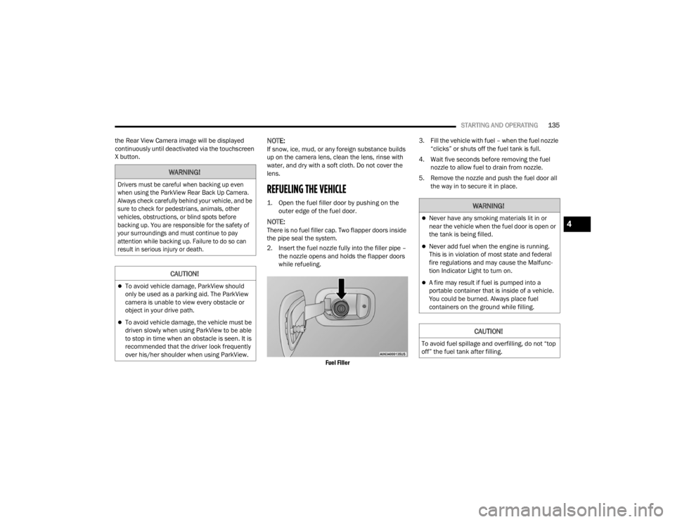
REFUELING THE VEHICLE
1. Open the fuel filler door by pushing on the outer edge of the fuel door.
NOTE:There is no fuel filler cap. Two flapper doors inside
the pipe seal the system.
2. Insert the fuel nozzle fully into the filler pipe – the nozzle opens and holds the flapper doors
while refueling.
Fuel Filler
3. Fill the vehicle with fuel – when the fuel nozzle
“clicks” or shuts off the fuel tank is full.
4. Wait five seconds before removing the fuel nozzle to allow fuel to drain from nozzle.
5. Remove the nozzle and push the fuel door all the way in to secure it in place.
WARNING!
Drivers must be careful when backing up even
when using the ParkView Rear Back Up Camera.
Always check carefully behind your vehicle, and be
sure to check for pedestrians, animals, other
vehicles, obstructions, or blind spots before
backing up. You are responsible for the safety of
your surroundings and must continue to pay
attention while backing up. Failure to do so can
result in serious injury or death.
CAUTION!
To avoid vehicle damage, ParkView should
only be used as a parking aid. The ParkView
camera is unable to view every obstacle or
object in your drive path.
To avoid vehicle damage, the vehicle must be
driven slowly when using ParkView to be able
to stop in time when an obstacle is seen. It is
recommended that the driver look frequently
over his/her shoulder when using ParkView.
WARNING!
Never have any smoking materials lit in or
near the vehicle when the fuel door is open or
the tank is being filled.
Never add fuel when the engine is running.
This is in violation of most state and federal
fire regulations and may cause the Malfunc -
tion Indicator Light to turn on.
A fire may result if fuel is pumped into a
portable container that is inside of a vehicle.
You could be burned. Always place fuel
containers on the ground while filling.
CAUTION!
To avoid fuel spillage and overfilling, do not “top
off” the fuel tank after filling.
4
23_WD_OM_EN_USC_t.book Page 135
Page 140 of 328
138STARTING AND OPERATING
Weight-Carrying Hitch
A weight-carrying hitch supports the trailer tongue
weight, just as if it were luggage located at a hitch
ball or some other connecting point of the vehicle.
These kinds of hitches are commonly used to tow
small and medium sized trailers.
Weight-Distributing Hitch
A weight-distributing system works by applying
leverage through spring (load) bars. They are
typically used for heavier loads to distribute trailer
tongue weight to the tow vehicle's front axle and the
trailer axle(s). When used in accordance with the
manufacturer's directions, it provides for a more
level ride, offering more consistent steering and
brake control thereby enhancing towing safety. The
addition of a friction/hydraulic sway control also
dampens sway caused by traffic and crosswinds and
contributes positively to tow vehicle and trailer
stability. Trailer Sway Control (TSC) and a weight
distributing (load equalizing) hitch are
recommended for heavier Tongue Weights (TW) and
may be required depending on vehicle and trailer
configuration/loading to comply with Gross Axle
Weight Rating (GAWR) requirements.
RECOMMENDED DISTRIBUTION HITCH
ADJUSTMENT
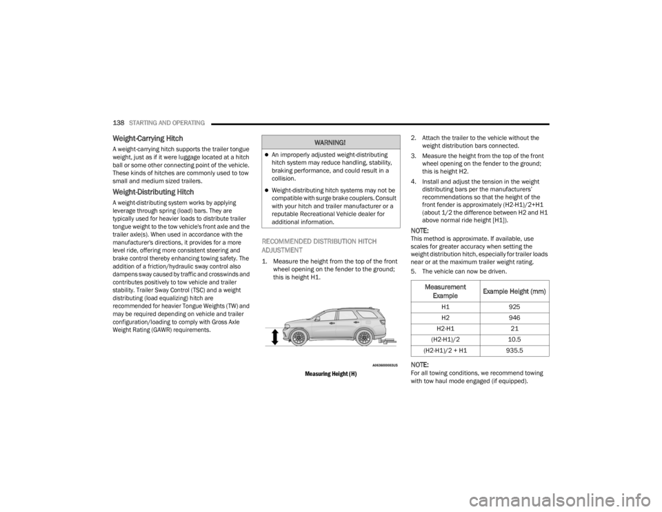
1. Measure the height from the top of the front
wheel opening on the fender to the ground;
this is height H1.
Measuring Height (H)
2. Attach the trailer to the vehicle without the
weight distribution bars connected.
3. Measure the height from the top of the front wheel opening on the fender to the ground;
this is height H2.
4. Install and adjust the tension in the weight distributing bars per the manufacturers’
recommendations so that the height of the
front fender is approximately (H2-H1)/2+H1
(about 1/2 the difference between H2 and H1
above normal ride height [H1]).
NOTE:This method is approximate. If available, use
scales for greater accuracy when setting the
weight distribution hitch, especially for trailer loads
near or at the maximum trailer weight rating.
5. The vehicle can now be driven.
NOTE:For all towing conditions, we recommend towing
with tow haul mode engaged (if equipped).
WARNING!
An improperly adjusted weight-distributing
hitch system may reduce handling, stability,
braking performance, and could result in a
collision.
Weight-distributing hitch systems may not be
compatible with surge brake couplers. Consult
with your hitch and trailer manufacturer or a
reputable Recreational Vehicle dealer for
additional information.
Measurement
Example Example Height (mm)
H1
925
H2 946
H2-H1 21
(H2-H1)/2 10.5
(H2-H1)/2 + H1 935.5
23_WD_OM_EN_USC_t.book Page 138
Page 157 of 328
MULTIMEDIA155
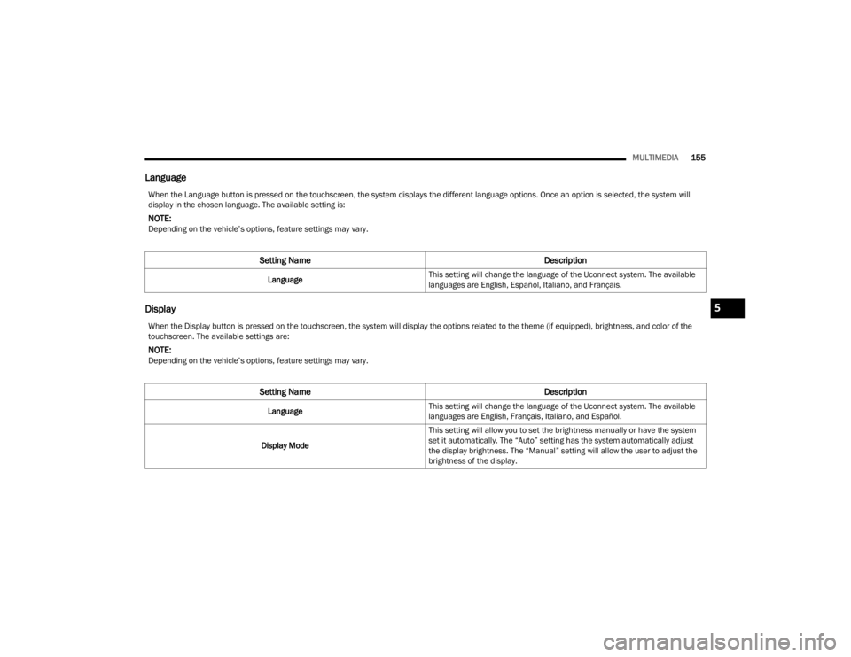
Language
Display
When the Language button is pressed on the touchscreen, the system displays the different language options. Once an option is selected, the system will
display in the chosen language. The available setting is:
NOTE:Depending on the vehicle’s options, feature settings may vary.
Setting Name Description
LanguageThis setting will change the language of the Uconnect system. The available
languages are English, Español, Italiano, and Français.
When the Display button is pressed on the touchscreen, the system will display the options related to the theme (if equipped), brightness, and color of the
touchscreen. The available settings are:
NOTE:Depending on the vehicle’s options, feature settings may vary.
Setting Name
Description
LanguageThis setting will change the language of the Uconnect system. The available
languages are English, Français, Italiano, and Español.
Display Mode This setting will allow you to set the brightness manually or have the system
set it automatically. The “Auto” setting has the system automatically adjust
the display brightness. The “Manual” setting will allow the user to adjust the
brightness of the display.
5
23_WD_OM_EN_USC_t.book Page 155
Page 159 of 328
MULTIMEDIA157
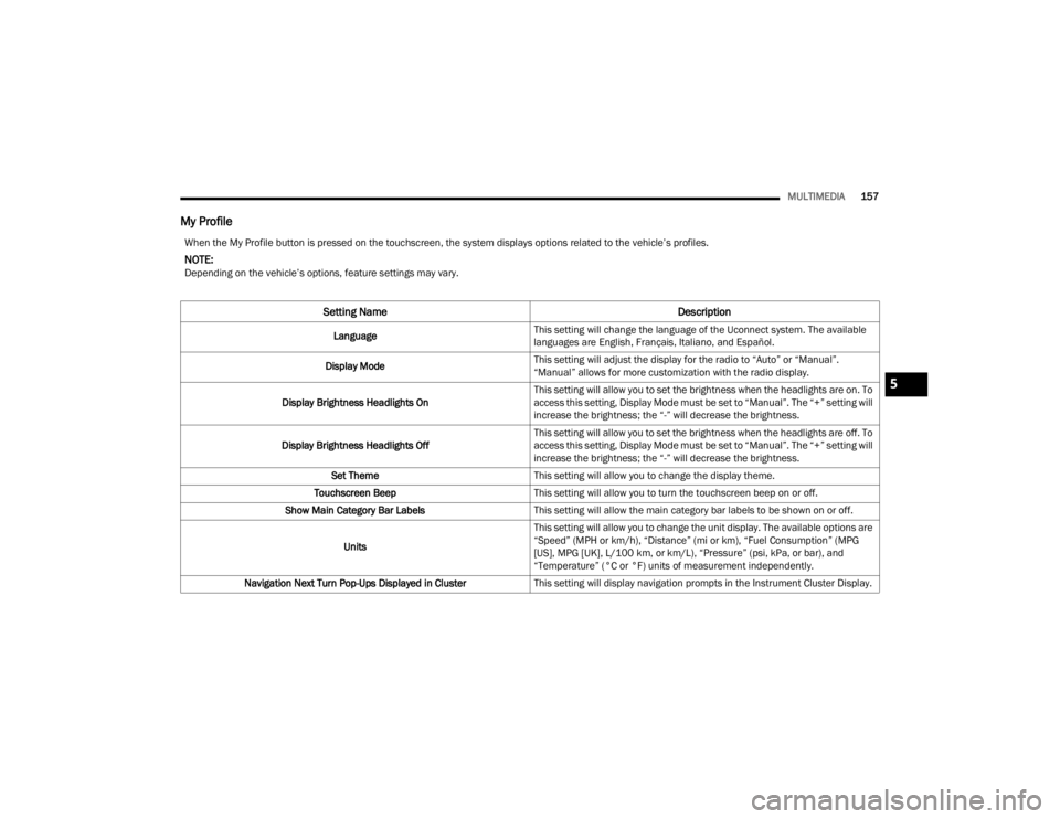
My Profile
When the My Profile button is pressed on the touchscreen, the system displays options related to the vehicle’s profiles.
NOTE:Depending on the vehicle’s options, feature settings may vary.
Setting Name Description
LanguageThis setting will change the language of the Uconnect system. The available
languages are English, Français, Italiano, and Español.
Display Mode This setting will adjust the display for the radio to “Auto” or “Manual”.
“Manual” allows for more customization with the radio display.
Display Brightness Headlights On This setting will allow you to set the brightness when the headlights are on. To
access this setting, Display Mode must be set to “Manual”. The “+” setting will
increase the brightness; the “-” will decrease the brightness.
Display Brightness Headlights Off This setting will allow you to set the brightness when the headlights are off. To
access this setting, Display Mode must be set to “Manual”. The “+” setting will
increase the brightness; the “-” will decrease the brightness.
Set Theme This setting will allow you to change the display theme.
Touchscreen Beep This setting will allow you to turn the touchscreen beep on or off.
Show Main Category Bar Labels This setting will allow the main category bar labels to be shown on or off.
Units This setting will allow you to change the unit display. The available options are
“Speed” (MPH or km/h), “Distance” (mi or km), “Fuel Consumption” (MPG
[US], MPG [UK], L/100 km, or km/L), “Pressure” (psi, kPa, or bar), and
“Temperature” (°C or °F) units of measurement independently.
Navigation Next Turn Pop-Ups Displayed in Cluster This setting will display navigation prompts in the Instrument Cluster Display.
5
23_WD_OM_EN_USC_t.book Page 157