buttons DODGE DURANGO 2023 Owner's Manual
[x] Cancel search | Manufacturer: DODGE, Model Year: 2023, Model line: DURANGO, Model: DODGE DURANGO 2023Pages: 328, PDF Size: 13.82 MB
Page 113 of 328
STARTING AND OPERATING111
4. After the AWD LOW position indicator light is on (not flashing), shift the transmission back into
gear.
NOTE:
If steps 1 or 2 of either the “Preferred” or “Alter -
nate Procedure” are not satisfied prior to
attempting the shift or if they no longer are
being met while the shift attempt is in process,
the desired position indicator light will flash
continuously while the original position indicator
light is on, until all requirements have been met.
The ignition switch must be in the ON/RUN posi -
tion for a shift to take place and for the position
indicator lights to be operable. If the ignition
switch is not in the ON/RUN position, then the
shift will not take place and no position indicator
lights will be on or flashing.
N (Neutral) Shift Procedure
For information regarding the transfer case N
(Neutral) shift procedure Ú page 148.
TOW N GO — IF EQUIPPED
Tow N Go combines the capabilities of the vehicle
control systems, along with driver input, to provide
optimum performance for road conditions.
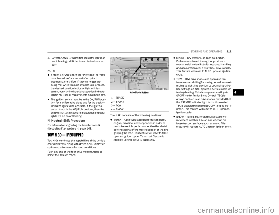
Push any one of the four drive mode buttons to
select the desired mode.
Drive Mode Buttons
Tow N Go consists of the following positions:
TRACK – Optimizes settings for transmission,
engine, driveline, and suspension in order to
maximize vehicle performance. Also the electric
power steering offers more feedback of the tire
gripping the road. This feature will reset to AUTO
upon an ignition cycle. To turn off Electronic
Stability Control (ESC) Ú page 180.
SPORT – Dry weather, on-road calibration.
Performance based tuning that provides a
rear-wheel drive feel but with improved handling
and acceleration over a two-wheel drive vehicle.
This feature will reset to AUTO upon an ignition
cycle.
TOW – TOW drive mode also optimizes the
transmission shifting for towing, as well as maxi -
mizing straight line traction by optimizing drive -
line settings on AWD system. Use this mode for
towing/hauling. Vehicle suspension will go to
SPORT mode. Trailer Sway Control (TSC) is
always enabled in all drive modes provided that
the ESC OFF indicator light is not illuminated.
TSC is disabled when the ESC OFF lamp is illumi -
nated. This feature will reset to AUTO upon an
ignition cycle.
SNOW – Tuning set for additional stability in
inclement weather. Use on and off-road on
loose traction surfaces such as snow. This
feature will reset to AUTO upon an ignition cycle.
1 — TRACK
2 — SPORT
3 — TOW
4 — SNOW
4
23_WD_OM_EN_USC_t.book Page 111
Page 117 of 328
STARTING AND OPERATING115
Battery voltage drops too low.
Stop/Start OFF switch is pushed.
A Stop/Start system error occurs.
Steering angle is beyond threshold.
TO MANUALLY TURN OFF THE STOP/
S
TART SYSTEM
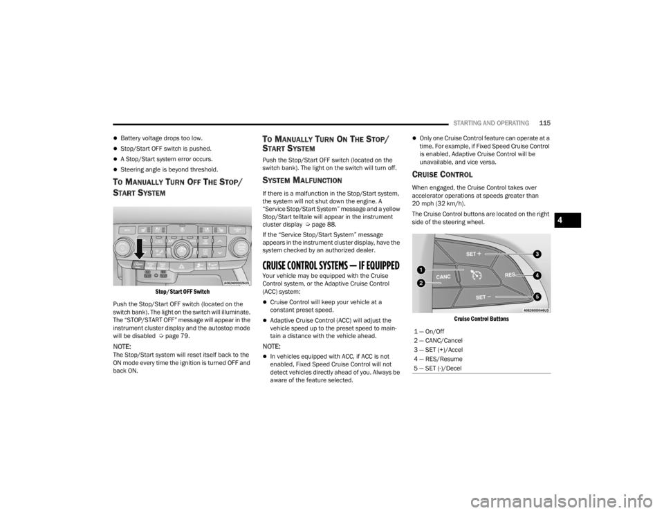
Stop/Start OFF Switch
Push the Stop/Start OFF switch (located on the
switch bank). The light on the switch will illuminate.
The “STOP/START OFF” message will appear in the
instrument cluster display and the autostop mode
will be disabled Ú page 79.
NOTE:The Stop/Start system will reset itself back to the
ON mode every time the ignition is turned OFF and
back ON.
TO MANUALLY TURN ON THE STOP/
S
TART SYSTEM
Push the Stop/Start OFF switch (located on the
switch bank). The light on the switch will turn off.
SYSTEM MALFUNCTION
If there is a malfunction in the Stop/Start system,
the system will not shut down the engine. A
“Service Stop/Start System” message and a yellow
Stop/Start telltale will appear in the instrument
cluster display Ú page 88.
If the “Service Stop/Start System” message
appears in the instrument cluster display, have the
system checked by an authorized dealer.
CRUISE CONTROL SYSTEMS — IF EQUIPPED Your vehicle may be equipped with the Cruise
Control system, or the Adaptive Cruise Control
(ACC) system:
Cruise Control will keep your vehicle at a
constant preset speed.
Adaptive Cruise Control (ACC) will adjust the
vehicle speed up to the preset speed to main -
tain a distance with the vehicle ahead.
NOTE:
In vehicles equipped with ACC, if ACC is not
enabled, Fixed Speed Cruise Control will not
detect vehicles directly ahead of you. Always be
aware of the feature selected.
Only one Cruise Control feature can operate at a
time. For example, if Fixed Speed Cruise Control
is enabled, Adaptive Cruise Control will be
unavailable, and vice versa.
CRUISE CONTROL
When engaged, the Cruise Control takes over
accelerator operations at speeds greater than
20 mph (32 km/h).
The Cruise Control buttons are located on the right
side of the steering wheel.
Cruise Control Buttons
1 — On/Off
2 — CANC/Cancel
3 — SET (+)/Accel
4 — RES/Resume
5 — SET (-)/Decel
4
23_WD_OM_EN_USC_t.book Page 115
Page 120 of 328
118STARTING AND OPERATING
Adaptive Cruise Control (ACC) Operation
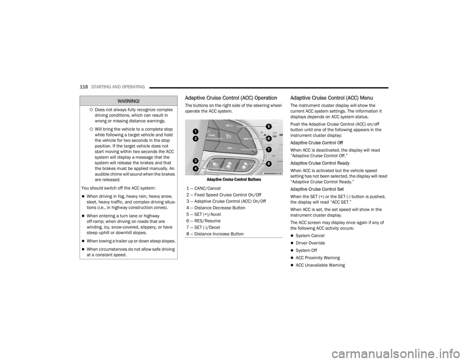
The buttons on the right side of the steering wheel
operate the ACC system.
Adaptive Cruise Control Buttons
Adaptive Cruise Control (ACC) Menu
The instrument cluster display will show the
current ACC system settings. The information it
displays depends on ACC system status.
Push the Adaptive Cruise Control (ACC) on/off
button until one of the following appears in the
instrument cluster display:
Adaptive Cruise Control Off
When ACC is deactivated, the display will read
“Adaptive Cruise Control Off.”
Adaptive Cruise Control Ready
When ACC is activated but the vehicle speed
setting has not been selected, the display will read
“Adaptive Cruise Control Ready.”
Adaptive Cruise Control Set
When the SET (+) or the SET (-) button is pushed,
the display will read “ACC SET.”
When ACC is set, the set speed will show in the
instrument cluster display.
The ACC screen may display once again if any of
the following ACC activity occurs:
System Cancel
Driver Override
System Off
ACC Proximity Warning
ACC Unavailable Warning
Does not always fully recognize complex
driving conditions, which can result in
wrong or missing distance warnings.
Will bring the vehicle to a complete stop
while following a target vehicle and hold
the vehicle for two seconds in the stop
position. If the target vehicle does not
start moving within two seconds the ACC
system will display a message that the
system will release the brakes and that
the brakes must be applied manually. An
audible chime will sound when the brakes
are released.
You should switch off the ACC system:
When driving in fog, heavy rain, heavy snow,
sleet, heavy traffic, and complex driving situa -
tions (i.e., in highway construction zones).
When entering a turn lane or highway
off-ramp; when driving on roads that are
winding, icy, snow-covered, slippery, or have
steep uphill or downhill slopes.
When towing a trailer up or down steep slopes.
When circumstances do not allow safe driving
at a constant speed.
WARNING!
1 — CANC/Cancel
2 — Fixed Speed Cruise Control On/Off
3 — Adaptive Cruise Control (ACC) On/Off
4 — Distance Decrease Button
5 — SET (+)/Accel
6 — RES/Resume
7 — SET (-)/Decel
8 — Distance Increase Button
23_WD_OM_EN_USC_t.book Page 118
Page 145 of 328
STARTING AND OPERATING143
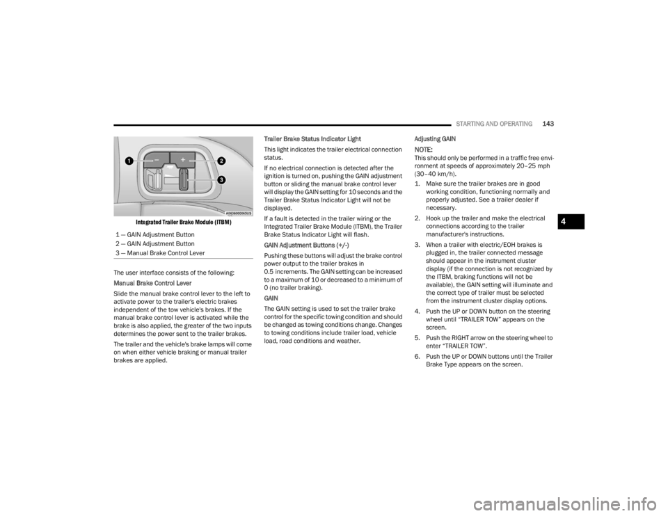
Integrated Trailer Brake Module (ITBM)
The user interface consists of the following:
Manual Brake Control Lever
Slide the manual brake control lever to the left to
activate power to the trailer's electric brakes
independent of the tow vehicle's brakes. If the
manual brake control lever is activated while the
brake is also applied, the greater of the two inputs
determines the power sent to the trailer brakes.
The trailer and the vehicle's brake lamps will come
on when either vehicle braking or manual trailer
brakes are applied. Trailer Brake Status Indicator Light
This light indicates the trailer electrical connection
status.
If no electrical connection is detected after the
ignition is turned on, pushing the GAIN adjustment
button or sliding the manual brake control lever
will display the GAIN setting for 10 seconds and the
Trailer Brake Status Indicator Light will not be
displayed.
If a fault is detected in the trailer wiring or the
Integrated Trailer Brake Module (ITBM), the Trailer
Brake Status Indicator Light will flash.
GAIN Adjustment Buttons (+/-)
Pushing these buttons will adjust the brake control
power output to the trailer brakes in
0.5 increments. The GAIN setting can be increased
to a maximum of 10 or decreased to a minimum of
0 (no trailer braking).
GAIN
The GAIN setting is used to set the trailer brake
control for the specific towing condition and should
be changed as towing conditions change. Changes
to towing conditions include trailer load, vehicle
load, road conditions and weather.
Adjusting GAIN
NOTE:This should only be performed in a traffic free envi
-
ronment at speeds of approximately 20–25 mph
(30–40 km/h).
1. Make sure the trailer brakes are in good working condition, functioning normally and
properly adjusted. See a trailer dealer if
necessary.
2. Hook up the trailer and make the electrical connections according to the trailer
manufacturer's instructions.
3. When a trailer with electric/EOH brakes is plugged in, the trailer connected message
should appear in the instrument cluster
display (if the connection is not recognized by
the ITBM, braking functions will not be
available), the GAIN setting will illuminate and
the correct type of trailer must be selected
from the instrument cluster display options.
4. Push the UP or DOWN button on the steering wheel until “TRAILER TOW” appears on the
screen.
5. Push the RIGHT arrow on the steering wheel to enter “TRAILER TOW”.
6. Push the UP or DOWN buttons until the Trailer Brake Type appears on the screen.
1 — GAIN Adjustment Button
2 — GAIN Adjustment Button
3 — Manual Brake Control Lever
4
23_WD_OM_EN_USC_t.book Page 143
Page 146 of 328
144STARTING AND OPERATING
7. Push the RIGHT arrow and then push the UP or DOWN buttons until the proper Trailer Brake
Type appears on the screen.
8. In a traffic-free environment, tow the trailer on a dry, level surface at a speed of 20–25 mph
(30–40 km/h) and squeeze the manual brake
control lever completely.
9. If the trailer wheels lockup (indicated by squealing tires), reduce the GAIN setting; if the
trailer wheels turn freely, increase the GAIN
setting.
Repeat steps 8 and 9 until the GAIN setting is at a point
just below trailer wheel lockup. If towing a heavier
trailer, trailer wheel lockup may not be attainable even
with the maximum GAIN setting of 10.
Display Messages
The trailer brake control interacts with the instrument
cluster display. Display messages, along with a single
chime, will be displayed when a malfunction is
determined in the trailer connection, trailer brake
control, or on the trailer
Ú
page 79.
NOTE:
An aftermarket controller may be available for
use with trailers with air or EOH trailer brake
systems. To determine the type of brakes on
your trailer and the availability of controllers,
check with your trailer manufacturer or dealer.
Removal of the ITBM will cause errors and it
may cause damage to the electrical system and
electronic modules of the vehicle. See an autho -
rized dealer if an aftermarket module is to be
installed.
Towing Requirements — Trailer Lights And
Wiring
Whenever pulling a trailer, regardless of the trailer
size, stoplights and turn signals on the trailer are
required for motoring safety.
The Trailer Tow Package may include a four- and
seven-pin wiring harness. Use a factory approved
trailer harness and connector.
NOTE:Do not cut or splice wiring into the vehicle’s wiring
harness.
The electrical connections are all complete to the
vehicle but you must mate the harness to a trailer
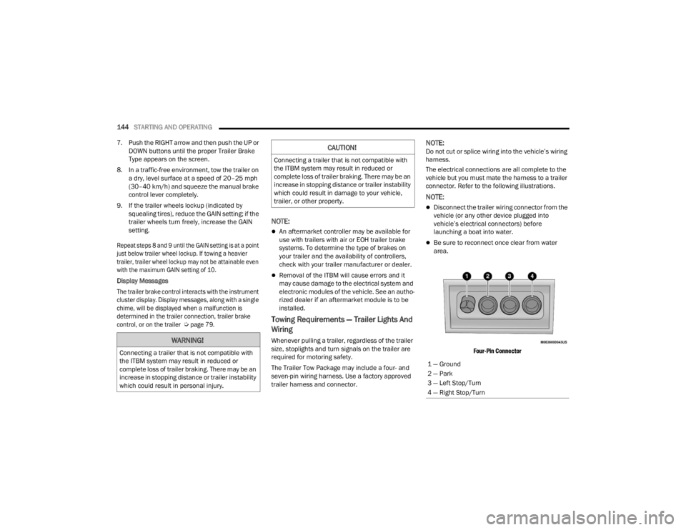
connector. Refer to the following illustrations.
NOTE:
Disconnect the trailer wiring connector from the
vehicle (or any other device plugged into
vehicle’s electrical connectors) before
launching a boat into water.
Be sure to reconnect once clear from water
area.
Four-Pin Connector
WARNING!
Connecting a trailer that is not compatible with
the ITBM system may result in reduced or
complete loss of trailer braking. There may be an
increase in stopping distance or trailer instability
which could result in personal injury.
CAUTION!
Connecting a trailer that is not compatible with
the ITBM system may result in reduced or
complete loss of trailer braking. There may be an
increase in stopping distance or trailer instability
which could result in damage to your vehicle,
trailer, or other property.
1 — Ground
2 — Park
3 — Left Stop/Turn
4 — Right Stop/Turn
23_WD_OM_EN_USC_t.book Page 144
Page 155 of 328
153
MULTIMEDIA
UCONNECT SYSTEMS
For detailed information about your Uconnect 4C/
4C NAV With 8.4-inch Display or Uconnect 5 NAV
With 10.1-inch Display systems, refer to your
Uconnect Owner’s Manual Supplement.
NOTE:Uconnect screen images are for illustration
purposes only and may not reflect exact software
for your vehicle.
CYBERSECURITY
Depending on applicability, your vehicle may be
able to send or receive information from a wired or
wireless network. This information allows systems
and features in your vehicle to function properly.
Your vehicle may be equipped with certain security
features to reduce the risk of unauthorized and
unlawful access to vehicle systems and wireless
communications. Vehicle software technology
continues to evolve over time and FCA US LLC,
working with its suppliers, evaluates and takes
appropriate steps as needed. As always, if you
experience unusual behavior, contact an
authorized dealer immediately, Úpage 308, or
refer to your Uconnect Owner’s Manual
Supplement for additional contact information. The risk of unauthorized and unlawful access to
your vehicle systems may still exist, even if the
most recent version of vehicle software (such as
Uconnect software) is installed.
NOTE:To help further improve user experience, features,
stability, etc., and minimize the potential risk of a
security breach, vehicle owners should routinely
check
www.driveuconnect.com (US Residents) or www.driveuconnect.ca (Canadian Residents) to
learn about available Uconnect software updates.
UCONNECT SETTINGS
The Uconnect system uses a combination of
buttons on the touchscreen and buttons on the
faceplate located on the center of the instrument
panel. These buttons allow you to access and
change the customer programmable features.
Many features can vary by vehicle.
Buttons on the faceplate are located below and/or
beside the Uconnect system in the center of the
instrument panel. In addition, there is a SCROLL/
ENTER control knob located on the right side. Turn
the control knob to scroll through menus and change
settings. Push the center of the control knob one or
more times to select or change a setting.
Your Uconnect system may also have SCREEN OFF
and MUTE buttons on the faceplate.
Push the SCREEN OFF button on the faceplate to
turn off the Uconnect screen. Push the button
again or tap the screen to turn the screen on.
Press the Back Arrow button to exit out of a Menu
or certain option on the Uconnect system.
On the Uconnect 5/5 NAV With 10.1-inch Display,
push and hold the Power button on the radio’s
faceplate for a minimum of 15 seconds to reset
the radio.
WARNING!
ONLY insert trusted media devices/compo -
nents into your vehicle. Media of unknown
origin could possibly contain malicious soft -
ware, and if installed in your vehicle, it may
increase the possibility for vehicle systems to
be breached.
As always, if you experience unusual vehicle
behavior, contact an authorized dealer imme -
diately.
5
23_WD_OM_EN_USC_t.book Page 153
Page 156 of 328
154MULTIMEDIA
CUSTOMER PROGRAMMABLE FEATURES
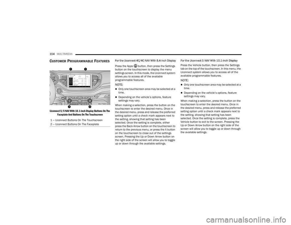
Uconnect 5/5 NAV With 10.1-inch Display Buttons On The
Faceplate And Buttons On The Touchscreen
For the Uconnect 4C/4C NAV With 8.4-inch Display
Press the Apps button, then press the Settings
button on the touchscreen to display the menu
settings screen. In this mode, the Uconnect system
allows you to access all of the available
programmable features.
NOTE:
Only one touchscreen area may be selected at a
time.
Depending on the vehicle’s options, feature
settings may vary.
When making a selection, press the button on the
touchscreen to enter the desired menu. Once in
the desired menu, press and release the preferred
setting option until a check mark appears next to
the setting, showing that setting has been
selected. Once the setting is complete, either
press the Back Arrow button on the touchscreen to
return to the previous menu, or press the X button
on the touchscreen to close out of the settings
screen. Pressing the Up or Down Arrow button on
the right side of the screen will allow you to toggle
up or down through the available settings. For the Uconnect 5 NAV With 10.1-inch Display
Press the Vehicle button, then press the Settings
tab on the top of the touchscreen. In this menu, the
Uconnect system allows you to access all of the
available programmable features.
NOTE:
Only one touchscreen area may be selected at a
time.
Depending on the vehicle’s options, feature
settings may vary.
When making a selection, press the button on the
touchscreen to enter the desired menu. Once in
the desired menu, press and release the preferred
setting option until a check mark appears next to
the setting, showing that setting has been
selected. Once the setting is complete, press the
Vehicle button to exit to the screen. Pressing the
Up or Down Arrow button on the right side of the
screen will allow you to toggle up or down through
the available settings.
1 — Uconnect Buttons On The Touchscreen
2 — Uconnect Buttons On The Faceplate
23_WD_OM_EN_USC_t.book Page 154
Page 231 of 328
229
IN CASE OF EMERGENCY
HAZARD WARNING FLASHERS
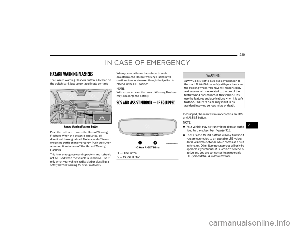
The Hazard Warning Flashers button is located on
the switch bank just below the climate controls.
Hazard Warning Flashers Button
Push the button to turn on the Hazard Warning
Flashers. When the button is activated, all
directional turn signals will flash on and off to warn
oncoming traffic of an emergency. Push the button
a second time to turn off the Hazard Warning
Flashers.
This is an emergency warning system and it should
not be used when the vehicle is in motion. Use it
only when your vehicle is disabled or signaling a
safety hazard warning for other motorists. When you must leave the vehicle to seek
assistance, the Hazard Warning Flashers will
continue to operate even though the ignition is
placed in the OFF position.
NOTE:With extended use, the Hazard Warning Flashers
may discharge the battery.
SOS AND ASSIST MIRROR — IF EQUIPPED
SOS And ASSIST Mirror
If equipped, the rearview mirror contains an SOS
and ASSIST button.
NOTE:
Your vehicle may be transmitting data as autho
-
rized by the subscriber Ú page 312.
The SOS and ASSIST buttons will only function if
you are connected to an operable LTE (voice/
data), 4G (data) network, which comes as a built
in function. Other Uconnect services will only be
operable if your SiriusXM Guardian™ service is
active and you are connected to an operable
LTE (voice/data), 4G (data) network.
1 — SOS Button
2 — ASSIST Button
WARNING!
ALWAYS obey traffic laws and pay attention to
the road. ALWAYS drive safely with your hands on
the steering wheel. You have full responsibility
and assume all risks related to the use of the
features and applications in this vehicle. Only
use the features and applications when it is safe
to do so. Failure to do so may result in an
accident involving serious injury or death.
7
23_WD_OM_EN_USC_t.book Page 229
Page 232 of 328
230IN CASE OF EMERGENCY
(Continued)
SOS Call
1. Push the SOS Call button on the Rearview
Mirror.
NOTE:In case the SOS Call button is pushed in error,
there will be a 10 second delay before the SOS Call
system initiates a call to a SOS operator. To cancel
the SOS Call connection, push the SOS call button
on the Rearview Mirror or press the cancellation
button on the Device Screen. Termination of the
SOS Call will turn off the green LED light on the
Rearview Mirror.
2. The LED light located between the ASSIST and SOS buttons on the Rearview Mirror will turn
green once a connection to a SOS operator has
been made.
3. Once a connection between the vehicle and a SOS operator is made, the SOS Call system
may transmit the following important vehicle
information to a SOS operator:
Indication that the occupant placed a SOS
Call
The vehicle brand
The last known GPS coordinates of the
vehicle 4. You should be able to speak with the SOS
operator through the vehicle audio system to
determine if additional assistance is needed.
NOTE:Once a connection is made between the vehicle’s
SOS Call system and the SOS operator, the SOS
operator may be able to open a voice connection
with the vehicle to determine if additional assis -
tance is needed. Once the SOS operator opens a
voice connection with the vehicle’s SOS Call
system, the operator should be able to speak with
you or other vehicle occupants and hear sounds
occurring in the vehicle. The vehicle’s SOS Call
system will attempt to remain connected with the
SOS operator until the SOS operator terminates
the connection.
5. The SOS operator may attempt to contact appropriate emergency responders and
provide them with important vehicle
information and GPS coordinates.
WARNING!
If anyone in the vehicle could be in danger
(e.g., fire or smoke is visible, dangerous road
conditions or location), do not wait for voice
contact from an Emergency Services Agent. All
occupants should exit the vehicle immediately
and move to a safe location.
Never place anything on or near the vehicle’s
operable network and GPS antennas. You
could prevent operable network and GPS
signal reception, which can prevent your
vehicle from placing an emergency call. An
operable network and GPS signal reception is
required for the SOS Call system to function
properly.
The SOS Call system is embedded into the
vehicle’s electrical system. Do not add after -
market electrical equipment to the vehicle’s
electrical system. This may prevent your
vehicle from sending a signal to initiate an
emergency call. To avoid interference that can
cause the SOS Call system to fail, never add
aftermarket equipment (e.g., two-way mobile
radio, CB radio, data recorder, etc.) to your
vehicle’s electrical system or modify the
antennas on your vehicle. IF YOUR VEHICLE
LOSES BATTERY POWER FOR ANY REASON
(INCLUDING DURING OR AFTER AN ACCI -
DENT), THE UCONNECT FEATURES, APPS AND
SERVICES, AMONG OTHERS, WILL NOT
OPERATE.
Modifications to any part of the SOS Call
system could cause the air bag system to fail
when you need it. You could be injured if the
air bag system is not there to help protect you.
WARNING!
23_WD_OM_EN_USC_t.book Page 230
Page 233 of 328
IN CASE OF EMERGENCY231
(Continued)
SOS Call System Limitations
Vehicles sold in Mexico
DO NOT have SOS Call
system capabilities.
SOS or other emergency line operators in Mexico
may not answer or respond to SOS system calls.
If the SOS Call system detects a malfunction, any
of the following may occur at the time the
malfunction is detected, and at the beginning of
each ignition cycle:
The Rearview Mirror light located between the
ASSIST and SOS buttons will continuously illumi -
nate red.
The Device Screen will display the following
message “Vehicle device requires service.
Please contact an authorized dealer.”
An In-Vehicle Audio message will state “Vehicle
device requires service. Please contact an
authorized dealer.” Even if the SOS Call system is fully functional,
factors beyond FCA US LLC’s control may prevent
or stop the SOS Call system operation. These
include, but are not limited to, the following
factors:
The ignition is in the OFF position
The vehicle’s electrical systems are not intact
The SOS Call system software and/or hardware
are damaged during a crash
The vehicle battery loses power or becomes
disconnected during a vehicle crash
LTE (voice/data), 4G (data) network and/or
Global Positioning Satellite signals are unavail
-
able or obstructed
Equipment malfunction at the SOS operator
facility
Operator error by the SOS operator
LTE (voice/data), 4G (data) network congestion
Weather
Buildings, structures, geographic terrain, or
tunnels
NOTE:
Never place anything on or near the vehicle’s
LTE (voice/data), 4G (data) and GPS antennas.
You could prevent LTE (voice/data), 4G (data)
and GPS signal reception, which can prevent
your vehicle from placing an emergency call. An
operable LTE (voice/data), 4G (data) network
connection and a GPS signal is required for the
SOS Call system to function properly.
Changes or modifications not expressly
approved by the party responsible for compli -
ance could void the user's authority to operate
the equipment.
WARNING!
Ignoring the Rearview Mirror light could mean
you will not have SOS Call services. If the Rear -
view Mirror light is illuminated, have an autho -
rized dealer service the SOS Call system
immediately.
The Occupant Restraint Control module turns
on the air bag Warning Light on the instrument
panel if a malfunction in any part of the
system is detected. If the Air Bag Warning
Light is illuminated, have an authorized dealer
service the Occupant Restraint Control system
immediately.
WARNING!
WARNING!
ALWAYS obey traffic laws and pay attention to
the road. ALWAYS drive safely with your hands on
the steering wheel. You have full responsibility
and assume all risks related to the use of the
features and applications in this vehicle. Only
use the features and applications when it is safe
to do so. Failure to do so may result in an
accident involving serious injury or death.
7
23_WD_OM_EN_USC_t.book Page 231